
Related Manuals for Toro 03952


Summary of Contents for Toro 03952
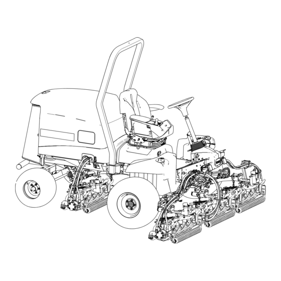
- Page 1 Operator’s Manual Reelmaster® 5410-D and 5510-D Traction Unit Model—Serial Range 03952—416400000 and Up 03954—416400000 and Up *3464-482* A 3464-482A Original Instructions (EN)
-
Page 2: Table Of Contents
After Operation Safety........................2–4 Maintenance Safety ......................... 2–4 Engine Safety ..........................2–5 Electrical System Safety ......................2–5 © 2024—The Toro ® Company Contact us at www.Toro.com 8111 Lyndale Ave So Printed in the USA Bloomington, MN 55044 All rights reserved... -
Page 3: Disclaimers And Regulatory Information
Cooling System Safety........................ 2–5 Hydraulic System Safety......................2–5 Blade Safety ..........................2–6 Storage Safety ..........................2–6 Safety and Instructional Decals ....................2–7 Chapter 3: Setup........................... 3–1 1 Preparing the Machine......................... 3–1 2 Adjusting the Control-Arm Position................... 3–1 3 Installing the Cutting Units ......................3–2 Preparing the Machine ........................ - Page 4 Overview of the Virtual Pedal Stop (VPS) Feature............. 5–16 Cruise Control ..........................5–17 Overview of the Acceleration Mode ..................5–18 Overview of the Warm-Up Mode..................... 5–19 Overview of Toro Smart Power™ ................... 5–19 Starting the Engine........................5–19 Shutting Off the Engine ......................5–19 Adjusting the Turf-Compensation Spring................5–20 Cutting Grass with the Machine ....................
- Page 5 Inspecting the Seat Belt ......................6–41 Cleaning............................6–42 Washing the Machine ........................ 6–42 Chapter 7: Storage..........................7–1 Storing the Machine ......................... 7–1 Storing the Battery..........................7–1 The Toro Warranty California Proposition 65 Warning Information 3464-482 A Disclaimers and Regulatory Information:...
-
Page 6: Chapter 1: Introduction
Whenever you need service, genuine Toro parts, or additional information, contact an Authorized Service Dealer or Toro Customer Service and have the model and serial numbers of your product ready. These numbers are located on the serial plate on your product . -
Page 7: Manual Conventions
Manual Conventions This manual identifies potential hazards and has safety messages identified by the safety- alert symbol, which signals a hazard that may cause serious injury or death if you do not follow the recommended precautions. G405934 This manual uses 2 words to highlight information. Important calls attention to special mechanical information and Note emphasizes general information worthy of special attention. -
Page 8: Chapter 2: Safety
Chapter 2 Safety General Safety • This product is capable of amputating hands and feet and of throwing objects. • Read and understand the contents of this Operator’s Manual before starting the engine. • Use your full attention while operating the machine. Do not engage in any activity that causes distractions;... -
Page 9: Fuel Safety
• Before mowing, always inspect the machine to ensure that the cutting units are in good working condition. • Inspect the area where you will use the machine and remove all objects that the machine could throw. • This product generates an electromagnetic field. If you wear an implantable electronic medical device, consult your health care professional before using this product. -
Page 10: Rollover Protection System (Rops) Safety
• Operate the engine only in well-ventilated areas. Exhaust gasses contain carbon monoxide, which is lethal if inhaled. • Do not leave a running machine unattended. • Before you leave the operator’s position, do the following: – Park the machine on a level surface. –... -
Page 11: After Operation Safety
Slope Safety (continued) – Remove or mark obstructions such as ditches, holes, ruts, bumps, rocks, or other hidden hazards. Tall grass can hide obstructions. Uneven terrain could overturn the machine. – Be aware that operating the machine on wet grass, across slopes, or downhill may cause the machine to lose traction. -
Page 12: Engine Safety
• Keep all parts of the machine in good working condition and all hardware tightened. • Replace all worn or damaged decals. • To ensure safe, optimal performance of the machine, use only genuine Toro replacement parts. Replacement parts made by other manufacturers could be dangerous, and such use could void the product warranty. -
Page 13: Blade Safety
Hydraulic System Safety (continued) • Keep your body and hands away from pinhole leaks or nozzles that eject high-pressure hydraulic fluid. • Use cardboard or paper to find hydraulic leaks. • Safely relieve all pressure in the hydraulic system before performing any work on the hydraulic system. -
Page 14: Safety And Instructional Decals
Safety and Instructional Decals Safety decals and instructions are easily visible to the operator and are located near any area of potential danger. Replace any decal that is damaged or missing. Battery Symbols Some or all of these symbols are on your battery. s_batterysymbols2 Wear eye protection;... - Page 15 Decal Part: 106-6755 Engine coolant under pressure. Explosion hazard—read the Operator's Manual. Warning—do not touch the hot surface. Warning—read the Operator's Manual. s_decal106-6755 Decal Part: 110-9642 Stored energy hazard—read the Operator's Manual. Move the cotter pin to the hole closest to the rod bracket and then remove the lift arm and pivot yoke.
- Page 16 Decal Part: 133-2930 s_decal133-2930 Warning—do not park on slopes; engage the Warning—do not operate this machine unless you parking brake, lower the cutting units, shut off the are trained. engine, and remove the ignition key before leaving Warning—wear hearing protection. the machine.
- Page 17 Decal Part: 133-2931 CE Machines s_decal133-2931 Note: This machine complies with the industry standard stability test in the static lateral and longitudinal tests with the maximum recommended slope indicated on the decal. Review the instructions for operating the machine on slopes in the Operator's Manual as well as the conditions in which you would operate the machine to determine whether you can operate the machine in the conditions on that day and at that site.
- Page 18 Decal Part: 136-2159 Move seat down Slide seat forward Rotate seat s_decal136-2159 Decal Part: 136-3702 Warning—Read the Operator’s Manual; wear a seatbelt; do not remove the roll bar. Warning—Do not modify the roll bar. s_decal136-3702 Decal Part: 137-8127 Attention—do not spray with high- pressure water.
- Page 19 Decal Part: 145-2483 Parking brake Cruise control Lower the cutting units. Raise the cutting units. PTO—Disengage PTO—Engage Read the Operator’s Manual. s_decal145-2483 Decal Part: 145-2519 TEC power relay Electrical power relay Read the Operator’s Manual for fuse information. Logic electrical power Air-ride seat Key switch Electrical power...
- Page 20 Decal Part: 145-2573 s_decal145-2573 Fuel Check every 8 hours. Read the Operator’s Manual for lubrication Brake functions information. Hydraulic fluid Read the Operator’s Manual. Tire pressure Fuel/Water separator Engine air filter Fluids Fan belt Capacity Engine coolant Fluid interval (hours) Battery Filter interval (hours) Radiator screen...
-
Page 21: Chapter 3: Setup
Chapter 3 Setup Preparing the Machine 1. Park the machine on a level surface, lower the cutting units, and engage the parking brake. 2. Shut off the engine, remove the key, and wait for all moving parts to stop. 3. Check the tire air pressure before use. Note: The tires are overinflated for shipping. -
Page 22: Installing The Cutting Units
Installing the Cutting Units Parts Required Right front hose guide Left front hose guide Preparing the Machine 1. Remove and discard the shipping brackets from the reel motors. 2. Remove the snapper pin and cap from each cutting-unit lift arm. G409088 Preparing the Cutting Units 1. -
Page 23: Positioning The Turf Compensating Spring And Installing The Hose Guide
Positioning the Turf Compensating Spring and Installing the Hose Guide Cutting Unit 4 G410291 Cutting unit 3 Cutting unit 5 Weight Cutting unit 1 Reel motor Cutting unit 2 Cutting unit 4 1. If the hairpin is installed in the rear hole of the compensation-spring rod, remove the hairpin and insert it in the hole next to the bracket. - Page 24 Positioning the Turf Compensating Spring and Installing the Hose Guide (continued) 3. Remove the flange locknut (3/8 inch) securing the bolt to the right tab of the carrier frame, and remove the compensation spring from the cutting unit. Note: Do not remove the flange serrated nut from the bolt.
-
Page 25: Installing The Hose Guide
Installing the Hose Guide Cutting Unit 5 G410309 Cutting unit 3 Cutting unit 5 Weight Cutting unit 1 Reel motor Cutting unit 2 Cutting unit 4 1. If the hairpin is installed in the rear hole of the compensation-spring rod, remove the hairpin and insert it in the hole next to the bracket. -
Page 26: Positioning The Turf Compensating Spring
Installing the Hose Guide (continued) 3. Align the studs of the right hose guide with the holes in the cutting-unit frame and the turf- compensator bracket Note: Ensure that the support loop of the hose guide aligns toward the center of the machine. - Page 27 Positioning the Turf Compensating Spring (continued) 2. Remove the 2 flange locknuts (3/8 inch) and 2 carriage bolts (3/8 x 1-1/4 inches) that secure the turf-compensator bracket the cutting-unit frame. G410293 3. Remove the flange locknut (3/8 inch) that secures the bolt of the turf compensation spring to the right tab of the carrier frame,...
-
Page 28: Installing The Kickstand
Installing the Kickstand For each cutting unit, secure the kickstand the chain bracket with the snapper pin G411001 Installing the Front Cutting Units to the Lift Arms 1. Install the front cutting units to the lift arms as shown. 2. Lock the cutting-unit pivot for cutting grass on a hill side. -
Page 29: Installing The Rear Cutting Units To The Lift Arms
Installing the Rear Cutting Units to the Lift Arms Cutting Units adjusted for a 1.2 cm (3/4 inch) or Higher Height of Cut 1. Install the rear cutting units to the lift arms as shown. 2. Lock the cutting-unit pivot for cutting grass on a hill side. -
Page 30: Locking The Cutting-Unit Pivot For Cutting Grass On A Hill Side
Locking the Cutting-Unit Pivot for Cutting Grass on a Hill Side Lock the cutting-unit pivots with snapper pins prevent the cutting units from rotating downhill when cutting across the face of a hill. Note: Use the hole in the pivot yoke to lock the cutting unit. - Page 31 Installing the Reel Motors (continued) G411002 4. Rotate the motor counterclockwise until the flanges encircle the bolts, and then tighten the bolts. IMPORTANT Ensure that the reel motor hoses are not twisted, kinked, or at risk of being pinched. 5. Torque the mounting bolts to 37 to 45 N∙m (27 to 33 ft-lb). 3464-482A Page 3–11 Setup: Installing the Cutting Units...
-
Page 32: Using The Cutting-Unit Kickstand
Using the Cutting-Unit Kickstand Parts Required Cutting-unit kickstand 1. When tipping a cutting unit to expose the bedknife/reel, prop up the rear of the cutting unit with the kickstand to ensure that the nuts on the back end of the bedbar adjusting screws are not resting on the work surface. -
Page 33: Installing The Ce Hood Lock
Installing the CE Hood Lock Parts Required Hood lock Seal Jam nut Washer 1. Raise the hood. 2. Remove the rubber grommet from the hole in the left side of the hood. G439569 3. Ensure that the seal is assembled to the hood lock 4. -
Page 34: Installing The Ce Decals
Installing the CE Decals CE Machines Parts Required Year of production decal CE decal Tilt danger decal Applying the CE Decal 1. Use rubbing alcohol and a clean rag to clean the area of the hood next to the hood lock and allow the hood to dry. -
Page 35: Applying The Ce Warning Decal
Applying the CE Warning Decal 1. Use rubbing alcohol and a clean rag to clean the surface of the existing decal and allow the decal to dry. 2. Remove the backing from the CE warning decal and apply the CE warning decal over the existing decal. -
Page 36: Chapter 4: Product Overview
Chapter 4 Product Overview Engine hood Operator's seat Control arm Steering wheel Seat-adjustment lever Front cutting units Rear cutting units G403840 Controls G461341 Headlight switch Key switch Tilt-steering pedal Parking-brake switch Lower mow/raise control lever Traction pedal Cruise-control switch InfoCenter display PTO switch Product Overview Page 4–1... -
Page 37: Automotive-Style Throttle
Automotive-Style Throttle Note: This machine does not have a lever or switch to control the engine speed. When the PTO is engaged to start spinning the cutting units, the machine automatically changes the engine speed to high idle and stays there until the cutting units are disengaged. When the PTO is not engaged, the throttle on the machine depends on the position of the traction pedal, just like the throttle on a car. -
Page 38: Parking-Brake Switch
Parking-Brake Switch Engage the parking brake. Note: Activating the parking-brake switch causes the traction to automatically decelerate (regardless of traction pedal position). The parking brake engages as soon as the machine comes to a stop or is shut off, regardless of the parking-brake switch position. -
Page 39: Power-Takeoff (Pto) Switch
Power-Takeoff (PTO) Switch Disengage PTO—The machine is in T mode (allows you to drive RANSPORT up to 16 km/h (10 mph) when the maximum speed is not limited). Engage PTO—The machine is in mode (allows you to drive up to 13 km/h (8 mph) when the maximum speed is not limited). -
Page 40: Tilt-Steering Pedal
Tilt-Steering Pedal Press the tilt-steering pedal and raise or lower the steering tower to a comfortable operating position. G453181 Traction Pedal Move forward—press the top of the pedal. Stop the machine—reduce foot pressure on the pedal and allow it to return to the center (neutral) position. -
Page 41: Hydraulic-Filter-Restriction Indicator
Hydraulic-Filter-Restriction Indicator The hydraulic-filter-restriction indicator alerts you when the hydraulic filters must be changed. G453944 Power Point The power point is a 12 V power supply for electronic devices. G453945 3464-482A Page 4–6 Product Overview: Controls... -
Page 42: Seat Controls
Seat Controls G446491 Height-adjustment knob Weight gauge Weight-adjustment knob Forward/backward lever Weight-Adjustment Knob Rotate the weight-adjustment knob until your weight is displayed in the window of the weight gauge. Decrease Increase G446496 Height-Adjustment Knob Raise Lower G446494 Product Overview: Controls Page 4–7 3464-482 A... -
Page 43: Backlap Levers
Seat Controls (continued) Forward/Backward Lever Lock Unlock G446495 Backlap Levers Use the backlap levers conjunction with the lower mow/ raise control lever for backlapping the reels. G454899 3464-482A Page 4–8 Product Overview: Controls... -
Page 44: Specifications
0 to 13 km/h (0 to 8 mph) Attachments/Accessories A selection of Toro approved attachments and accessories is available for use with the machine to enhance and expand its capabilities. Contact your Authorized Service Dealer or authorized Toro distributor or go to www.Toro.com... -
Page 45: Chapter 5: Operation
Chapter 5 Operation Before Operation Performing Daily Maintenance Before starting the machine each day, perform the Each Use/Daily procedures listed in the Maintenance Schedule. Fuel Fuel Specifications IMPORTANT Use only ultra-low sulphur diesel fuel. Fuel with higher rates of sulfur degrades the diesel oxidation catalyst (DOC), which causes operational problems and shortens the service life of engine components. - Page 46 Monitor seals, hoses, gaskets in contact with fuel as they may degrade over time. Fuel filter plugging may be expected for a time after converting to biodiesel blended. For more information on biodiesel, contact your authorized Toro distributor. Storage Acquire only enough clean, fresh diesel fuel or biodiesel fuel that you will consume within 180 days.
-
Page 47: Checking The Interlock Switches
• Check the operation of the interlock switches daily and replace any damaged switches before operating the machine. IMPORTANT If your machine fails any of the interlock switch checks, contact your authorized Toro distributor. Preparing the Machine 1. Drive the machine slowly to an open area. - Page 48 Checking the Interlock Switches (continued) Checking the Traction Pedal Start-Interlock 1. Sit in the operator’s seat and engage the parking brake. 2. Press the PTO switch to the D position. ISENGAGE 3. Press the traction pedal and rotate the key to the S position.
-
Page 49: Overview Of The Infocenter Display
Checking the Interlock Switches (continued) Checking the Automatic Parking Brake Engage 1. Sit in the operator’s seat and start the engine. 2. Disengage the parking brake and rise from the seat. Note: The red light on the parking-brake switch should illuminate when you are out of the operator’s seat, indicating that the parking brake is on. - Page 50 Overview of the InfoCenter Display (continued) InfoCenter Display Icons Service is due. Engine-coolant temperature (°C or °F) Engine rpm/status— The PTO is engaged. indicates the engine speed (rpm) Hour meter Start the engine. Fuel level Engine Fuel is low. PIN passcode The glow plugs are A parked or recovery active.
- Page 51 Description Faults The Faults menu contains a list of the recent machine faults. Refer to the Service Manual or contact your authorized Toro distributor for more information on the Faults menu and the information contained there. Service The Service menu contains information on the machine such as hours of use, counters, and other similar numbers.
- Page 52 Overview of the InfoCenter Display (continued) Service Menu Item Description Hours Lists the total number of hours that the machine, engine and PTO have been on, as well as the number of hours the machine has been transported and service due. Counts Lists numerous counts the machine has experienced.
- Page 53 Overview of the InfoCenter Display (continued) Machine Settings Menu Item Description Front Backlap Controls the speed of the front reels in backlap mode. Rear Backlap Controls the speed of the rear reels in backlap mode. Mow Speed Controls the maximum speed while in mow (low range).
- Page 54 Note: The factory default PIN code for you machine is either 0000 or 1234. If you changed the PIN code and forgot the code, contact your authorized Toro distributor for assistance. 1. From the Main Menu, scroll down to Settings and press the select button.
- Page 55 Overview of the InfoCenter Display (continued) 2. In Settings, scroll to Enter PIN and press the select button 3. To enter the PIN code, press the up/down navigation buttons until the correct first digit appears, then press the right navigation button to move on to the next digit.
- Page 56 Overview of the InfoCenter Display (continued) 7. After you select Y , the interval screen clears and reverts back to the service hours selections. Setting the Blade Count 1. In Machine Settings, scroll down to Blade Count. 2. Press the right navigation button to change the blade count between 8 or 11 blade reels. Setting the Height of Cut (HOC) 1.
- Page 57 Overview of the InfoCenter Display (continued) 1. In Machine Settings, scroll down to Transport Speed. 2. Use the left and right navigation buttons to increase and decrease the maximum transport speed in 0.8 km/h (0.5 mph) increments between 8.0 and 16.0 km/h (5.0 and 10.0 mph).
-
Page 58: Checking The Hydrostatic Braking Distance
4. Check if the machine stops within 0.6 m (2 ft) of the end mark (3.7 m or 12 ft). 5. Contact your Toro distributor if the stopping distance of the machine is not within 0.6 m (2 ft) of this distance. -
Page 59: During Operation
During Operation Overview of the Machine Operating Characteristics • This machine has an automotive-style throttle that is controlled by the traction pedal. • This machine does not have a separate throttle switch or throttle lever. • When you remove your foot from the traction pedal, the machine dynamically brakes to a stop. -
Page 60: Overview Of The Traction Pedal
Overview of the Traction Pedal The traction pedal controls the forward and reverse speed of the machine and the dynamic braking when you return it to neutral. • This machine has an automotive-style throttle — the engine speed and the machine speed respond to the pedal movement. -
Page 61: Cruise Control
Overview of the Virtual Pedal Stop (VPS) Feature (continued) • This feature allows you to customize the speed settings for your comfort level, or to customize the speed settings to fit the application. • Whenever the maximum traction speed is changed via the supervisor maximum speed settings or Virtual Pedal Stop, the traction pedal is automatically reprogrammed to use the full pedal stroke between neutral and the new maximum speed. -
Page 62: Overview Of The Acceleration Mode
Cruise Control (continued) 2. Use the InfoCenter display to adjust the speed setting of the cruise control. G462143s Indicates the maximum This speed is locked out Indicates the cruise control traction speed (pedal stop) under the protected PIN speed menu. Tips for Using the Cruise Control •... -
Page 63: Overview Of The Warm-Up Mode
Do not operate the machine until after the warm-up period. Overview of Toro Smart Power™ With Smart Power, the operator does not have to listen to the engine speed in heavy load conditions. -
Page 64: Adjusting The Turf-Compensation Spring
Adjusting the Turf-Compensation Spring The turf-compensation spring transfers weight from the front to the rear roller. This helps to reduce a wave pattern in the turf, also known as marcelling or bobbing. IMPORTANT Make spring adjustments with the cutting unit mounted to the traction unit, pointing straight ahead and lowered to the ground. -
Page 65: Understanding The Diesel-Particulate Filter And Regeneration
Cutting Grass with the Machine (continued) 10. When nearing the opposite edge of the fairway (prior to reaching the edge of the mowing area), tap the lift/lower control lever rearward to lift the cutting units to the turnaround position. 11. Perform a tear-shaped turn to quickly line up for your next pass. 12. - Page 66 Understanding the Diesel-Particulate Filter and Regeneration (continued) CAUTION The exhaust temperature is hot (approximately 600°C (1,112°F) during DPF regeneration. Hot exhaust gas can harm you or other people. • Do not operate the engine in an enclosed area. • Ensure that there are no flammable materials around the exhaust system. •...
- Page 67 Understanding the Diesel-Particulate Filter and Regeneration (continued) Types of Diesel Particulate Filter Regeneration Types of diesel particulate filter regeneration that are performed while the machine is operating: Type of Conditions that cause DPF DPF description of operation Regeneration regeneration Passive Occurs during normal operation of the •...
- Page 68 Understanding the Diesel-Particulate Filter and Regeneration (continued) Types of diesel particulate filter regeneration that require you to park the machine: Type of Conditions that cause DPF DPF description of operation Regeneration regeneration Parked Occurs because the computer • When the reset-standby/parked or determines that the automatic DPF cleaning has not been sufficient.
- Page 69 Understanding the Diesel-Particulate Filter and Regeneration (continued) Using the DPF Regeneration Menus Accessing the DPF Regeneration Menus 1. From the Main Menu, scroll down to Service and press the select button. 2. In Service, scroll to DPF Regeneration and press the select button. 3.
- Page 70 Understanding the Diesel-Particulate Filter and Regeneration (continued) Note: If you set the InfoCenter to inhibit regeneration, the InfoCenter displays an advisory every 15 minutes while the engine requests a reset regeneration. IMPORTANT When you shut off the engine and start it again, the inhibit regen setting defaults to 1.
- Page 71 Understanding the Diesel-Particulate Filter and Regeneration (continued) 3. At the R screen, verify that you have 1/4 tank of fuel if you are EGEN ARAMETERS performing the parked regeneration or 1/2 tank of fuel if you are performing the recovery regeneration.
-
Page 72: Adjusting The Lift-Arm Counterbalance
Adjusting the Lift-Arm Counterbalance Rear Cutting Units CAUTION The springs are under tension, and adjusting them could result in minor or moderate personal injury. Use caution when adjusting the springs. Adjust the amount of counterbalance force applied to the rear cutting-units to help compensate for different turf conditions, and to maintain a uniform height of cut in rough conditions or in areas of thatch buildup. -
Page 73: Adjusting The Lift-Arm Turnaround Position
Adjusting the Lift-Arm Turnaround Position 1. Park the machine on a level surface, lower the cutting units, shut off the engine, engage the parking brake, and remove the key. 2. Locate the lift-arm switch underneath the hydraulic tank and inboard of the cutting unit #5 lift arm. -
Page 74: Setting The Reel Speed
Setting the Reel Speed IMPORTANT It is important that proper reel speeds are used for your mowing application. • Reel speeds that are too slow may result in a wave pattern in the turf, also known as clip marks, marcelling, or bobbing. If this is observed, try increasing the reel speeds or reducing the mowing speed. -
Page 75: Overview Of The Indicator Lights
Setting the Reel Speed (continued) 7 inch (178 mm) Reel Speed Chart G439056 Overview of the Indicator Lights G461477 Indicator light • Flashing red—active fault • Solid red—active advisory • Solid blue—calibration/dialog messages • Solid green—normal operation 3464-482A Page 5–31 Operation: During Operation... -
Page 76: Operating Tips
Operating Tips Overview of the Warning System If a warning light comes on during operation, stop the machine immediately and correct the problem before continuing operation. Serious damage could occur if you operate the machine with a malfunction. Overview of Mowing Patterns This is the most effective method to prevent washboarding. - Page 77 Operating Tips (continued) – Do not use Economy Mode. – Use the InfoCenter display to monitor both engine coolant and generator temperatures. – Frequently check the rear radiator screen and the air cleaner air inlet screen above the radiator for chaff build up. –...
-
Page 78: After Operation
After Operation Tie-Down Point Locations • Front of the machine—the hole in the rectangular pad, under the axle tube, inside each front tire. G439095 Front tie-down • Rear of the machine—each side of the machine on the rear frame. G439096 Rear tie-down Operation: After Operation Page 5–34... -
Page 79: Hauling The Machine
Hauling the Machine Follow the tips below when hauling the machine. • Use full-width ramps for loading the machine onto a trailer or truck. • Tie the machine down securely. Pushing or Towing the Machine In an emergency, you can move the machine forward by actuating the bypass valve in the variable-displacement hydraulic pump and pushing or towing the machine. - Page 80 Note: Because the fluid is bypassed, the machine can be moved slowly without damaging the transmission. 4. Locate the brake release manifold near the front right tire and behind the hydraulic tank. 5. Insert a tube or similar object, hold the black knob in on the manifold, and pump manifold 3 times.
-
Page 81: Chapter 6: Maintenance
Determine the left and right sides of the machine from the normal operating position. Note: Download a free copy of the electrical or hydraulic schematic by visiting www.Toro.com searching for your machine from the Manuals link on the home page. IMPORTANT Refer to your engine owner’s manual and cutting unit Operator's Manual for... - Page 82 Maintenance Description Maintenance Procedure Part No. Service Interval PX Extended Life Hydraulic 133-8086 Fluid (5 gallons) Check the hydraulic-fluid level. PX Extended Life Hydraulic 133-8087 Fluid (55 gallons) Inspect the hydraulic lines and hoses. Check the reel to bedknife contact. Grease the bearings and Premium all-purpose grease bushings (and immediately after...
- Page 83 Maintenance Description Maintenance Procedure Part No. Service Interval the reservoir with an alternative fluid). Replace the return-hydraulic filter Hydraulic filter 75-1310 and charge-hydraulic filter (if you are not using the recommended hydraulic fluid or have ever filled Hydraulic filter 94-2621 the reservoir with an alternative fluid).
-
Page 84: Daily Maintenance Checklist
Daily Maintenance Checklist Duplicate this page for routine use. Maintenance Check Item For the week of: Mon. Tues. Wed. Thurs. Fri. Sat. Sun. Check the safety interlock operation. Check the brake operation. Check the levels of the engine oil and fuel. Drain the water/fuel separator. -
Page 85: Pre-Maintenance Procedures
Notation for Areas of Concern Inspection performed by: Item Date Information Pre-Maintenance Procedures Preparing for Maintenance 1. Park the machine on a level surface, disengage the PTO, lower the cutting units, and engage the parking brake. 2. Shut off the engine, remove the key, wait for all moving parts to stop, and allow the engine to cool. -
Page 86: Closing The Hood
Closing the Hood Carefully rotate the hood closed and secure it with the 2 hood latches G437871 Opening the Screen 1. Remove the ball pin from the screen latch 2. Unlatch and open the screen. G437863 Maintenance: Pre-Maintenance Procedures Page 6–6 3464-482 A... -
Page 87: Closing The Screen
Closing the Screen 1. Close and latch the screen. 2. Insert the ball pin through the screen latch G414734 Tilting the Seat 1. Unlatch the seat base 2. Tilt the seat and base open 3. Support it with the prop rods G443836 Lowering the Seat 1. -
Page 88: Jacking Point Locations
Jacking Point Locations Note: Support the machine with jack stands whenever you work under the machine. Use the following as machine-lift points: • Front—the jack brackets of the front-axle tube. • Rear—the rear-axle tube. G437877 Rear-axle tube Front of the machine Jack brackets (front-axle tube) Back of the machine Lubrication... -
Page 89: Grease Fitting Locations
Greasing the Bearings and Bushings (continued) Grease Fitting Locations Grease Specification: No. 2 lithium grease Pump driveshaft (3) G452381 Cutting-unit lift-arm cylinders (2 each) Lift-arm pivots (1 each) G452355 Cutting-unit carrier-frame and pivot (2 each) G452356 Lift-arm-pivot shaft (1 each) G452357 3464-482A Page 6–9... - Page 90 Greasing the Bearings and Bushings (continued) Axle-steering pivot (1) G452379 Steering-cylinder ball joints (2) G452380 Maintenance: Lubrication Page 6–10 3464-482 A...
-
Page 91: Engine Maintenance
Engine Maintenance Checking the Air Cleaner 1. Prepare the machine for maintenance. 2. Open the hood. 3. Check the service indicator at the end of the air filter housing. G415048 4. If a red band displays in the service indicator, change the air filter. -
Page 92: Servicing The Air Cleaner
Servicing the Air Cleaner • Check the whole intake system for leaks, damage, or loose hose clamps. Do not use a damaged air filter. • Service the air-cleaner filter only when the service indicator requires it. Changing the air filter before it is necessary only increases the chance of dirt entering the engine when you remove the filter. -
Page 93: Engine Oil Specifications
Use the following engine oil viscosity grade: • Preferred oil: SAE 15W-40 [-17°C (above 0°F)] • Alternate oil: SAE 10W-30 or 5W-30 (all temperatures) Toro Premium Engine Oil is available from your authorized Toro distributor in either 15W-40 or 10W-30 viscosity grades. Crankcase Capacity Approximately 5.2 L (5.5 US qt) with the filter... -
Page 94: Checking The Engine Oil Level
Checking the Engine Oil Level Note: Check the oil when the engine is cool. If the engine is warm, wait 10 minutes before checking. IMPORTANT Check the engine oil daily. If the engine-oil level is above the Full mark on the dipstick, the engine oil may be diluted with fuel. -
Page 95: Changing The Engine Oil And Filter
Changing the Engine Oil and Filter 1. Prepare the machine for maintenance. 2. Drain the oil and change the filter. G414766 G437920 IMPORTANT Do not overtighten the filter. 3. Open the hood. 4. Add oil to the crankcase. 5. Close and latch the hood. 3464-482A Page 6–15 Maintenance: Engine Maintenance... -
Page 96: Fuel System Maintenance
Fuel System Maintenance This Operator’s Manual contains more detailed fuel and fuel system maintenance information than the engine Owner’s Manual, which is a general-purpose reference relating to fuel and fuel maintenance. Ensure that you understand that the fuel system maintenance, fuel storage, and fuel quality require your attention to avoid downtime and extensive engine repairs. -
Page 97: Servicing The Fuel/Water Separator
Servicing the Fuel/Water Separator Draining Water from the Fuel/Water Separator 1. Drain water from the fuel/water separator as shown. G452998 2. Prime the filter and the lines to the high pressure pump. 3464-482A Page 6–17 Maintenance: Fuel System Maintenance... - Page 98 Servicing the Fuel/Water Separator (continued) Replacing the Fuel/Water Separator Filter 1. Replace the filter as shown. G452996 2. Prime the filter and the lines to the high pressure pump. Maintenance: Fuel System Maintenance Page 6–18 3464-482 A...
-
Page 99: Servicing The Fuel Filter
DPF. 2. Contact to your authorized Toro distributor for diesel-oxidation catalyst and the soot filter replacement parts or service. 3. Contact your authorized Toro distributor to reset the engine ECU after installing a clean DPF. 3464-482A Page 6–19... -
Page 100: Cleaning The Fuel-Pickup Tube Screen
Cleaning the Fuel-Pickup Tube Screen Removing the Fuel-Pickup Tube The fuel-pickup tube, located inside the fuel tank, is equipped with a screen to help prevent debris from entering the fuel system. Remove the fuel-pickup tube and clean the screen as required. - Page 101 Cleaning the Fuel-Pickup Tube Screen (continued) 5. Loosen the fuel-sender cap 6. Carefully lift the fuel sender from the tank. Note: Do not bend the pick-up tube, return tube, or float arm. G415058 Cleaning the Installing the Fuel-Pickup Tube 1. Clean the screen at the end of the fuel pick-up tube.
-
Page 102: Priming The Fuel System
Cleaning the Fuel-Pickup Tube Screen (continued) 5. Assemble the hose onto the fittings the fuel sender, and secure the hoses to the fittings with the clamps G415057 6. Plug the connector of the fuel-sender harness into the connector of the machine wire harness G415056 7. -
Page 103: Electrical System Maintenance
Priming the Fuel System (continued) IMPORTANT Do not use the engine-starter motor to crank the engine for fuel-system priming. 1. Ensure that fuel is in the fuel tank. 2. Perform the following steps to prime the filter and the lines to the high-pressure pump to prevent wear or damage to the pump: A. -
Page 104: Connecting The Battery
2. Install the negative battery cable (black) the negative (-) battery post. 3. Apply a coat of Grafo 112X (skin-over) grease, Toro Part No. 505-47 to the battery posts and battery-cable clamps. 4. Slide the rubber boot over the positive battery- cable clamp. -
Page 105: Servicing The Battery
Servicing the Battery Note: Keep the terminals and the entire battery case clean because a dirty battery will discharge slowly. 1. Prepare the machine for maintenance. 2. Open the screen. 3. Check the condition of the battery. Note: Replace a worn or damaged battery. 4. -
Page 106: Replacing The Ecu Fuse
Replacing the TEC Fuse (continued) 3. At the rear right side of the engine, remove the cover of the in-line fuse holder 4. Replace the open fuse with a fuse of the same type and amperage rating. 5. Assemble the cap to the in-line fuse holder. 6. -
Page 107: Drive System Maintenance
Drive System Maintenance Checking the Tire Pressure WARNING Low tire pressure decreases machine side hill stability. This could cause a rollover, which could result in death or serious injury. Do not under-inflate the tires. Note: Maintain the recommended pressure in all tires to ensure a good quality of cut and proper machine performance. -
Page 108: Adjusting The Rear Wheel Toe-In
Checking the Rear-Wheel Alignment (continued) G416236 Center-to-center distance Front of the traction unit 6 mm (1/4 inch) or less than the rear of the tire 4. If the measurement is greater than 6 mm (1/4 inch), adjust the rear wheel toe-in. Adjusting the Rear Wheel Toe-in 1. -
Page 109: Cooling System Maintenance
Cooling System Maintenance Coolant Specifications The coolant reservoir is filled at the factory with a 50/50 solution of water and ethylene glycol base extended-life coolant. IMPORTANT Use only commercially available coolants that meet the specifications listed in the Extended Life Coolant Standards Table. Do not use conventional (green) inorganic-acid technology (IAT) coolant in your machine. -
Page 110: Checking The Coolant Level
Coolant Specifications (continued) Cooling system capacity Approximately 9.5 L (10.0 US qt) Checking the Coolant Level CAUTION If the engine has been running, the pressurized, hot coolant can escape, which could result in minor or moderate injury. • Do not open the radiator cap when the engine is running. •... -
Page 111: Inspecting The Cooling System Hoses
Checking the Coolant Level (continued) G452997 Hot engine-coolant mark Cold engine-coolant mark Cap (coolant reservoir) 4. If the coolant level is low, remove the coolant-reservoir cap and add the specified coolant until the level it is at the cold mark (for a cold engine) or hot mark (for a hot engine). -
Page 112: Cleaning The Engine Cooling System
Cleaning the Engine Cooling System 1. Prepare the machine for maintenance. 2. Raise the hood. 3. Thoroughly clean all debris out of the engine area. 4. Close and latch the hood. 5. Release the rear screen latches and pivot the rear screen open. -
Page 113: Belt Maintenance
The reservoir is filled at the factory with high-quality hydraulic fluid. Check the level of the hydraulic fluid before you first start the engine and daily thereafter. Recommended hydraulic fluid: Toro PX Extended Life Hydraulic Fluid; available in 19 L (5 US gallon) pails or 208 L (55 US gallon) drums. -
Page 114: Checking The Hydraulic-Fluid Level
Toro Premium Synthetic Biodegradable Hydraulic Fluid is the only synthetic biodegradable fluid approved by Toro. This fluid is compatible with the elastomers used in Toro hydraulic systems and is suitable for a wide-range of temperature conditions. This fluid is compatible with conventional mineral oils, but for maximum biodegradability and performance, the hydraulic system should be thoroughly flushed of conventional fluid. -
Page 115: Inspecting The Hydraulic Lines And Hoses
Checking the Hydraulic-Fluid Level (continued) G417019 Add mark (dipstick) Full mark (dipstick) 5. If the level is low, add the appropriate amount of the specified fluid to raise the level to the full mark. 6. Install the dipstick onto the filler neck. Inspecting the Hydraulic Lines and Hoses Inspect the hydraulic lines and hoses for leaks, kinked lines, loose mounting supports, wear, loose fittings, weather deterioration, and chemical deterioration. - Page 116 Replacing the Hydraulic Filters (continued) Changing the Return Filter The hydraulic system is equipped with a return filter-service indicator . You view the filter- service indicator through the hole in the floor plate. With the engine running at operating temperature, check the color of the indicator as follows: •...
-
Page 117: Changing The Hydraulic Fluid
Repair all hydraulic leaks. Changing the Hydraulic Fluid If the fluid becomes contaminated, contact your Toro Distributor because the system must be flushed. Contaminated fluid looks milky or black when compared to clean fluid. 1. Prepare the machine for maintenance. -
Page 118: Cutting Unit Maintenance
Changing the Hydraulic Fluid (continued) G439327 90° fitting Manifold Loosen fitting here 3. Disconnect the 90° fitting from the manifold and allow the tank to drain. 4. When hydraulic fluid stops draining from the tank, connect the 90° fitting to the manifold. 5. -
Page 119: Backlapping The Cutting Units
• Never attempt to turn the cutting units by hand or foot while the engine is running. Note: Additional instructions and procedures on backlapping are available in the Toro Reel Mower Basics (with sharpening guidelines), Form 09168SL. Preparing the Machine 1. - Page 120 Backlapping the Cutting Units (continued) Note: Select either the front, rear, or both backlap levers to control which cutting units to backlap. When backlapping, the front cutting units all operate together, and the rear cutting units operate together. Lapping the Reels and Bedknife WARNING Changing the engine speed while backlapping may cause the cutting units to stall, which could result in death or serious injury.
-
Page 121: Chassis Maintenance
Backlapping the Cutting Units (continued) Finishing Backlapping 1. Move the Lower Mow/Raise lever rearward and disengage the PTO. 2. Shut off the engine and remove the key. 3. Move the backlap levers to the F (mow) position. IMPORTANT If you do not change backlap lever to the F (mow) position after backlapping, the cutting units will not function properly. -
Page 122: Cleaning
Cleaning Washing the Machine Wash the machine as needed using water alone or with a mild detergent. You may use a rag when washing the machine. IMPORTANT • Do not use brackish or reclaimed water to clean the machine. • Do not use power-washing equipment to wash the machine. Power-washing equipment may damage the electrical system, loosen important decals, or wash away necessary grease at friction points. -
Page 123: Chapter 7: Storage
A. Remove the battery terminals from the battery posts. B. Clean the battery, terminals, and posts with a wire brush and baking-soda solution. C. Coat the cable terminals and battery posts with Grafo 112X skin-over grease (Toro Part No. 505-47) or petroleum jelly to prevent corrosion. - Page 124 the charge in the battery. To prevent the battery from freezing, ensure that it is fully charged. The specific gravity of a fully charged battery is 1.265 to 1.299. Storage: Storing the Battery Page 7–2 3464-482 A...
-
Page 125: The Toro Warranty
Conditions and Products Covered Toro. Toro will make the final decision whether to repair any existing part or assembly or replace it. Toro may use remanufactured parts for warranty repairs. -
Page 126: California Proposition 65 Warning Information
Toro has chosen to provide consumers with as much information as possible so that they can make informed decisions about the products they buy and use. Toro provides warnings in certain cases based on its knowledge of the presence of one or more listed chemicals without evaluating the level of exposure, as not all the listed chemicals provide exposure limit requirements. - Page 127 Notes:...