
Related Manuals for Toro 03966


Summary of Contents for Toro 03966
- Page 1 Form No. 3462-825 Rev A Reelmaster ® 5610-D Traction Unit Model No. 03966—Serial No. 400000000 and Up *3462-825* Register at www.Toro.com. Original Instructions (EN)
- Page 2 Whenever you need service, genuine Toro parts, or additional information, contact an Authorized Service g000502 Figure 2 Dealer or Toro Customer Service and have the model Safety-alert symbol and serial numbers of your product ready. Figure 1 identifies the location of the model and serial numbers on the product.
-
Page 3: Table Of Contents
Replacing a 12 V Fuse-Block Fuse ....56 Understanding the Warm-Up Mode....32 Replacing the TEC Fuse........57 Understanding Toro Smart Power™ ....33 Drive System Maintenance ........58 Starting the Engine ........... 33 Checking the Tire Air Pressure......58 Shutting Off the Engine........ -
Page 4: Safety
Safety Hydraulic Fluid Specifications......62 Checking the Hydraulic-Fluid Level....62 Checking the Hydraulic Lines and General Safety Hoses............63 Replacing the Hydraulic Filters ......63 Hydraulic Fluid Capacity ........64 This product is capable of amputating hands and feet Changing the Hydraulic Fluid ......64 and of throwing objects. -
Page 5: Safety And Instructional Decals
Safety and Instructional Decals Safety decals and instructions are easily visible to the operator and are located near any area of potential danger. Replace any decal that is damaged or missing. decal106-6754 decalbatterysymbols 106-6754 Battery Symbols 1. Warning—do not touch the hot surface. Some or all of these symbols are on your battery. - Page 6 decal120-4158 120-4158 1. Read the Operator’s 3. Engine—preheat Manual. 2. Engine—start 4. Engine—stop decal136-3702 136-3702 1. Warning—Read the 2. Warning—Do not modify Operator’s Manual; wear the roll bar. a seatbelt; do not remove the roll bar. decal136-2159 136-2159 1. Move seat down 3.
- Page 7 decal145-2519 145-2519 1. TEC power relay 5. Air-ride seat 2. Electrical power relay 6. Electrical power 3. Read the Operator's 7. Headlights decal145-2484 Manual for fuse 145-2484 information. 4. Key switch 8. USB power point 1. Parking brake 6. Raise the cutting units 2.
- Page 8 decal145-2572 145-2572 1. Read the Operator’s 6. Engine air filter 11. Engine coolant 16. Fluids Manual for lubrication information. 7. Engine oil 12. Engine oil level 2. Check every 8 hours. 17. Capacity 3. Brake functions 8. Fan belt 13. Fuel 18.
-
Page 9: Setup
Setup Loose Parts Use the chart below to verify that all parts have been shipped. Procedure Description Qty. – No parts required Prepare the machine. – No parts required Adjust the control-arm position. Right front hose guide Install the cutting units. Left front hose guide Cutting-unit kickstand Install the cutting-unit kickstand. -
Page 10: Installing The Cutting Units
Loosen the 2 bolts securing the control arm to the retaining bracket (Figure g003975 Figure 4 1. Snapper pin 2. Cap Preparing the Cutting Units Remove the cutting units from the cartons. Assemble and adjust as described in the cutting g004152 unit Operator's Manual. - Page 11 Positioning the Turf Compensating Spring and Installing the Hose Guide Cutting Units 4 g375690 Figure 8 1. Carriage bolt (3/8 x 1-1/4 3. Flange locknut (3/8 inch) g375671 inches) Figure 6 2. Turf-compensator bracket 1. Cutting unit 1 5. Cutting unit 5 2.
- Page 12 Installing the Hose Guide Cutting Units 5 g375672 Figure 12 g375694 Figure 10 1. Cutting unit 1 5. Cutting unit 5 1. Flange locknut (3/8 inch) 3. Capscrew 6. Reel motor 2. Cutting unit 2 2. Right tab (Carrier frame) 7.
- Page 13 Positioning the Turf Compensating Spring Cutting Unit 2 g379514 g375690 Figure 16 Figure 14 1. Cutting unit 1 5. Cutting unit 5 1. Carriage bolt (3/8 x 1-1/4 3. Flange locknut (3/8 inch) 6. Reel motor 2. Cutting unit 2 inches) 7.
- Page 14 g375690 Figure 18 g375694 Figure 20 1. Carriage bolt (3/8 x 1-1/4 3. Flange locknut (3/8 inch) 1. Flange locknut (3/8 inch) 3. Capscrew inches) 2. Right tab (Carrier frame) 2. Turf-compensator bracket Align the holes in the turf-compensator bracket Remove the flange locknut (3/8 inch) that with the holes in the cutting-unit frame (Figure...
- Page 15 Lock the cutting-unit pivot for cutting grass on a hill side; refer to Locking the Cutting-Unit Pivot for Cutting Grass on a Hill Side (page 16). Installing the Rear Cutting Units to the Lift Arms Cutting Units adjusted for a 1.2 cm (3/4 inch) or Higher Height of Cut Slide a cutting unit under the lift arm (Figure...
- Page 16 g375236 Figure 25 g375239 1. Lynch pin 3. Lift arm (rear cutting unit) Figure 27 2. Pivot yoke 4. Washer 1. Lynch pin 3. Lift arm 2. Lift-arm shaft 4. Washer Assemble the pivot yoke onto the carrier frame shaft (Figure 26).
-
Page 17: Using The Cutting-Unit Kickstand
Using the Cutting-Unit Kickstand Parts needed for this procedure: g003948 Figure 29 Cutting-unit kickstand 1. Lift-arm chain 3. Snapper pin 2. Chain bracket Procedure Whenever you must tip the cutting unit to expose the bedknife/reel, prop up the rear of the cutting unit with Installing the Reel Motors the kickstand to ensure that the nuts on the back end of the bedbar adjusting screws are not resting on the... -
Page 18: Applying The Production Year Decal
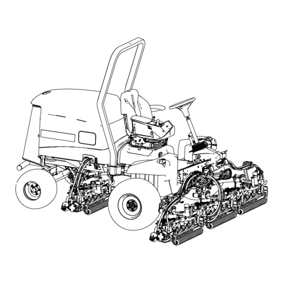
Product Overview g216864 Figure 34 g004144 Figure 32 1. Engine hood 5. Seat adjustments 2. Seat 6. Front cutting units 3. Control arm 7. Rear cutting units 4. Steering wheel Applying the Production Controls Year Decal Parts needed for this procedure: Production year decal Procedure Use rubbing alcohol and a clean rag to clean the... - Page 19 Power-takeoff (PTO) Switch When the PTO switch is engaged, the machine is in mode, which allows you to drive up to 13 km/h (8 mph) when the maximum speed is not limited. When the PTO switch is not engaged (Figure 37), the machine is in T mode, which allows you...
-
Page 20: Seat Controls
Backlap Levers diagnostics, and other information about the machine (Figure 35). Use the backlap levers in conjunction with the lower The screens that display, depend on which buttons mow/raise control lever for backlapping the reels you select. The purpose of each button may change (Figure 40). -
Page 21: Specifications
To ensure optimum performance and continued safety certification of the machine, use only genuine Toro replacement parts and accessories. Replacement parts and accessories made by other manufacturers could be dangerous, and such use could void the... -
Page 22: Before Operation
Operation • Do not add or drain fuel in an enclosed space. • Do not store the machine or fuel container where there is an open flame, spark, or pilot light, such Before Operation as on a water heater or other appliance. •... -
Page 23: Fuel Tank Capacity
Important: If your machine fails any of the Adding Fuel interlock switch checks, contact your authorized Toro distributor. Park the machine on a level surface, lower the cutting units, engage the parking brake, shut off Preparing the Machine the engine, and remove the key. -
Page 24: Using The Infocenter Lcd Display
Checking the Parking Brake and Traction Pedal Run-Interlock Sit in the operator’s seat. Engage the parking brake. Press the PTO switch to the D position. ISENGAGE Start the engine. Press the traction pedal. Note: There should be no machine response when you press the traction pedal while the parking brake is engaged. -
Page 25: Using The Menus
Indicates when the cutting units are faults. Refer to the Service being raised Manual or your Authorized Toro Distributor for more PIN passcode information on the Faults menu and the information contained there. CAN bus... -
Page 26: Protected Menus
Settings The Settings menu allows Allows the ability to change Protect Settings you to customize and modify the settings in the protected configuration variables on the settings InfoCenter display. Low, Medium, and High Acceleration About The About menu lists the settings control how quickly model number, serial number, the traction speed reacts when... - Page 27 Wait until the red indicator light of the InfoCenter is either 0000 or 1234. illuminates. If you changed the PIN code and forgot the code, contact your authorized Toro distributor for assistance. Note: If the InfoCenter accepts the PIN code and the protected menu is unlocked, the word...
-
Page 28: Checking The Hydrostatic Braking Distance
Setting the Blade Count Setting the Maximum Allowed Transport Speed In the Settings Menu, scroll down to Blade Count. The selected setting is displayed as an X on the Press the right button to change the blade count traction-speed bar graph along with the cruise control between 8 or 11 blade reels. -
Page 29: Understanding Displayed Traction Speeds
(3.7 m or 12 ft). • Look behind and down before backing up to be Contact your Toro distributor if the stopping sure of a clear path. distance of the machine is not within 0.6 m (2 •... -
Page 30: Understanding The Operating Characteristics Of The Machine
Slope Safety maintain consistent control over rough terrain, while still allowing for quick, smooth braking. • Slopes are a major factor related to loss of control • The maximum speeds set in the PIN protected and rollover accidents, which can result in severe menu settings are set by the supervisor to limit the injury or death. -
Page 31: Using The Virtual Pedal Stop (Vps) Feature
neutral. The machine dynamically brakes to a stop. This traction system allows you to customize the acceleration settings for operator comfort and course conditions. Refer to Accessing Protected Menus (page 27) for changing the settings. g322245 Figure 47 1. Indicates the maximum 2. -
Page 32: Understanding The Acceleration Mode
Tips for Using the Cruise Control • When in transport range, press the reverse traction pedal, engage the parking brake, or press the • Set a cruising speed for long distances without cruise control switch to the O positon. many obstacles. •... -
Page 33: Understanding Toro Smart Power
Cutting Grass with the InfoCenter screen. Do not operate the machine above low idle until after the warm-up period. Machine Understanding Toro Smart Disengage the parking brake, disengage the PTO, and raise the cutting units. Power™ Move the throttle to the F position. -
Page 34: Setting The Reel Speed
Setting the Reel Speed Important: It is important that proper reel speeds are used for your mowing application. Reel speeds that are too slow may result in a wave pattern in the turf, also known as clip marks, marcelling, or bobbing. If this is observed, try increasing the reel speeds or reducing the mowing speed. Reel speeds that are too fast may result in turf damage and/or premature wear of the reels, bedknives, and other mechanical components. -
Page 35: Adjusting The Lift-Arm Turnaround Position
Park the machine on a level surface, lower the cutting units, shut off the engine, engage the parking brake, and remove the key. Insert the long end of the counterbalance spring into a tube or similar object, and pivot the spring around the shouldered stud to the desired position (Figure... -
Page 36: Understanding The Diagnostic Light
g003863 g021272 Figure 54 Figure 55 1. Turf-compensation spring 3. Spring rod 1. Diagnostic light 2. Hairpin 4. Hex nuts Operating Tips Tighten the hex nuts on the front end of the spring rod until the compressed length of the spring is 15.9 cm (6.25 inches);... -
Page 37: After Operation
• Verticutting avoid sharp turns on slopes to prevent rollovers. Lower the cutting units when going downhill for – For 5-inch verticutters, set the verticutter steering control. blade depth to 1/8 inch or less. For 7-inch verticutters, set the blade depth to 1/4 inch or Maintaining the Machine after less. -
Page 38: Pushing Or Towing The Machine
Pushing or Towing the Machine In an emergency, you can move the machine forward by actuating the bypass valve in the variable-displacement hydraulic pump and pushing or towing the machine. Important: Do not push or tow the machine faster than 3 to 4.8 km/h (2 to 3 mph). If you push or tow at a faster speed, internal transmission damage may occur. - Page 39 g420086 Figure 59 1. Pump mechanism on the 2. Black knob brake manifold Insert the long end of a ratchet or similar object, hold the black knob in on the manifold, and pump the manifold 3 times. As soon as there is substantial resistance when pumping the brake is released.
-
Page 40: Maintenance
• To ensure safe, optimal performance of the slip-resistant footwear. Keep hands, feet, clothing, machine, use only genuine Toro replacement jewelry, and long hair away from moving parts. parts. Replacement parts made by other •... - Page 41 Maintenance Service Maintenance Procedure Interval • Inspect the cooling system hoses. Every 100 hours • Check the condition and tension of the alternator belt. • Change the engine oil and filter. Every 150 hours • Drain moisture from the fuel and hydraulic fluid tanks. Every 200 hours •...
-
Page 42: Daily Maintenance Checklist
Refer to your engine owner’s manual and cutting unit Operator's Manual for additional maintenance procedures. Note: Download a free copy of the electrical or hydraulic schematic by visiting www.Toro.com and searching for your machine from the Manuals link on the home page. -
Page 43: Pre-Maintenance Procedures
Pre-Maintenance Procedures Preparing for Maintenance Park the machine on a level surface, disengage the PTO, lower the cutting units, and engage the parking brake. Shut off the engine, remove the key, and wait for all moving parts to stop. Wait for the engine to cool. Opening the Hood Release the 2 hood latches (Figure... -
Page 44: Tilting The Seat
Jacking Point Locations Note: Support the machine with jack stands whenever you work under the machine. Use the following as machine-lift points: g378174 Figure 63 1. Ball pin 2. Screen latch Insert the ball pin through the screen latch. Tilting the Seat Unlatch the seat base (A of Figure 64). -
Page 45: Lubrication
Lubrication • Lift-arm pivots (1 each) (Figure • Cutting-unit carrier-frame and pivot (2 each) (Figure Greasing the Bearings and Bushings Service Interval: Every 50 hours (and immediately after every washing). Grease Specification: No. 2 lithium grease Prepare the machine for maintenance; refer to Preparing for Maintenance (page 43). -
Page 46: Engine Maintenance
Engine Maintenance Engine Safety • Shut off the engine before checking the oil or adding oil to the crankcase. • Do not change the governor speed or overspeed the engine. Checking the Air Filter g003966 Figure 71 Service Interval: Before each use or daily Prepare the machine for maintenance;... -
Page 47: Servicing The Air Cleaner
g034923 g373568 Figure 73 Close and latch the hood; refer to Closing the Hood (page 43). Servicing the Air Cleaner Service Interval: Every 400 hours (more frequently in extremely dirty or dusty conditions). Service the air cleaner earlier if the air-cleaner indicator shows red. -
Page 48: Resetting The Air Filter Service Indicator
Preferred oil: SAE 15W-40 (above 0°F) • Alternate oil: SAE 10W-30 or 5W-30 (all temperatures) Toro Premium Engine Oil is available from your authorized Toro distributor in either 15W-40 or 10W-30 viscosity grades. Checking the Level of the Engine Oil... -
Page 49: Changing The Engine Oil And Filter
Changing the Engine Oil Important: Do not overtighten the filter. Open the hood; refer to Opening the Hood (page and Filter 43). Service Interval: After the first 50 hours—Change Add oil to the crankcase; refer to Oil Specification the engine oil and filter. (page 48), Crankcase Oil Capacity (page... -
Page 50: Fuel System Maintenance
Fuel System provider to correct the problem and perform all fuel system maintenance. Maintenance • Do not store diesel fuel in tanks or canisters made with zinc-plated components. Fuel Maintenance Servicing the Fuel-Water This Operator’s Manual contains more detailed fuel Separator and fuel system maintenance information than the engine Owner’s Manual, which is a general-purpose... -
Page 51: Bleeding The Fuel System
g421595 Figure 80 1. Fuel-injection pump bleed screw Turn the key in the ignition switch to the O position. The electric fuel pump runs, forcing air out around the air-bleed screw. Note: Leave the key in the O position until a solid stream of fuel flows out around the screw. -
Page 52: Cleaning The Fuel-Pickup Tube Screen
stored for an extended period. Use clean fuel to flush out the tank. Prepare the machine for maintenance; refer to Preparing for Maintenance (page 43). Align a drain container under the drain valve at the bottom of the fuel tank (Figure 81). - Page 53 Cleaning the Installing the Fuel-Pickup Tube Clean the screen at the end of the fuel pick-up tube (Figure 86). g373882 Figure 84 1. Hoses 3. Fitting (fuel sender) 2. Clamp Loosen the fuel-sender cap (Figure 85). g373881 Figure 86 Carefully assemble the fuel pick-up tube and float into the fuel tank (Figure 87).
-
Page 54: Priming The Fuel System
g373882 Figure 88 1. Hoses 3. Fitting (fuel sender) 2. Clamp g373885 Figure 90 Plug the connector of the fuel-sender harness 1. Fuel-sender cover 3. Fuel tank into the connector of the machine wire harness 2. Phillips-head screw (Figure 89). Priming the Fuel System Prime the fuel system after the following scenarios: •... -
Page 55: Electrical System Maintenance
Electrical System Maintenance Electrical System Safety • Disconnect the battery before repairing the machine. Disconnect the negative terminal first and the positive last. Connect the positive terminal first and the negative last. • Charge the battery in an open, well-ventilated area, away from sparks and flames. -
Page 56: Charging The 12 V Battery
Replacing a 12 V Apply a coat of Grafo 112X (skin-over) grease, Toro Part No. 505-47 to the battery posts and Fuse-Block Fuse battery-cable clamps. Slide the rubber boot over the positive The fuse block is under the seat. battery-cable clamp. -
Page 57: Replacing The Tec Fuse
g422229 Figure 96 1. TEC fuse g420144 Figure 94 Replace the open fuse with a fuse of the same 1. Fuse block type and amperage rating. Assemble the cap to the in-line fuse holder. Rotate the seat and seat base closed and latch Close and latch the hood;... -
Page 58: Drive System Maintenance
Drive System Note: The rear wheel toe-in adjustment is correct if the difference between the front wheel Maintenance measurement and the rear wheel measurement is 6 mm (1/4 inch) or less. (Figure 97). Checking the Tire Air Pressure Service Interval: Before each use or daily Important: Maintain the recommended pressure in all tires to ensure a good quality of cut and... -
Page 59: Cooling System Maintenance
Cooling System At axle height, measure the center-to-center distance at the front and rear of the steering Maintenance tires. Note: The rear wheel toe-in adjustment is correct if the difference between the front wheel Cooling System Safety measurement and the rear wheel measurement is 6 mm (1/4 inch) or less. -
Page 60: Checking The Coolant Level
• Preferred option: If distilled water is not available, Close and latch the hood; refer to Closing the use a pre-mix coolant instead of a concentrate. Hood (page 43). • Minimum requirement: If distilled water and pre-mix coolant are not available, mix concentrated Removing Debris from the coolant with clean drinkable water. -
Page 61: Belt Maintenance
Belt Maintenance Servicing the Alternator Belt Service Interval: Every 100 hours Park the machine on a level surface, lower the cutting units, engage the parking brake, shut off the engine, and remove the key. Open the hood; refer to Opening the Hood (page 43). -
Page 62: Hydraulic System Maintenance
Toro. system. This fluid is compatible with the elastomers used in Toro hydraulic systems and is suitable for a Hydraulic Fluid wide-range of temperature conditions. This fluid is compatible with conventional mineral oils, but for... -
Page 63: Checking The Hydraulic Lines And Hoses
fluid, replace the return-hydraulic filter and charge-hydraulic filter. Important: Use of any other filters may void the warranty on some components. Changing the Return Filter The hydraulic system is equipped with a return filter-service indicator (Figure 105). You view the filter-service indicator through the hole in the floor plate. -
Page 64: Hydraulic Fluid Capacity
g422076 Figure 107 1. Filter head 2. Charge filter g376340 Figure 106 1. Return filter 2. Filter head Remove the filter. Wipe clean the filter mounting area of the filter Remove the filter. head. Apply a thin coat of the specified hydraulic fluid Wipe clean the filter mounting area of the filter to the gasket of the new charge filter. - Page 65 Hydraulic-Fluid Level (page 62) filled the reservoir with an alternative fluid, change the hydraulic fluid. If the fluid becomes contaminated, contact your Toro Distributor because the system must be flushed. Contaminated fluid looks milky or black when compared to clean fluid.
-
Page 66: Cutting Unit Maintenance
Note: Additional instructions and procedures on DANGER backlapping are available in the Toro Reel Mower Changing the engine speed while backlapping Basics (with sharpening guidelines), Form 09168SL. may cause the reels to stall. - Page 67 position. Move the Lower Mow/Lift control forward to start the backlapping operation on the designated reels. Apply lapping compound with a long-handled brush. DANGER Contacting the cutting units when they are moving could cause personal injury. g377117 Figure 110 To avoid personal injury, be certain that 1.
-
Page 68: Chassis Maintenance
Extended Maintenance Chassis Maintenance Inspecting the Seat Belt Chassis and Engine Service Interval: Before each use or daily Service Interval: Every 2 years—Replace the hydraulic hoses. Inspect the seat belt for wear, cuts, and other damage. Replace the seat belt(s) if any Every 2 years—Replace the coolant hoses. -
Page 69: Cleaning
Clean the battery, terminals, and posts with a wire brush and baking-soda solution. Coat the cable terminals and battery posts with Grafo 112X skin-over grease (Toro Part No. 505-47) or petroleum jelly to prevent corrosion. Slowly charge the battery every 60 days for 24 hours to prevent lead sulfation of the battery. -
Page 70: Storing The Battery
Remove and discard the oil filter. Install a new oil filter. Fill the engine with specified motor oil. Start the engine and run it at idle speed for approximately 2 minutes. Shut off the engine and remove the key. Flush the fuel tank with fresh, clean fuel. Secure all of the fuel-system fittings. - Page 71 The Toro Company (“Toro”) respects your privacy. When you purchase our products, we may collect certain personal information about you, either directly from you or through your local Toro company or dealer. Toro uses this information to fulfil contractual obligations - such as to register your warranty, process your warranty claim or to contact you in the event of a product recall - and for legitimate business purposes - such as to gauge customer satisfaction, improve our products or provide you with product information which may be of interest.
- Page 72 Countries Other than the United States or Canada Customers who have purchased Toro products exported from the United States or Canada should contact their Toro Distributor (Dealer) to obtain guarantee policies for your country, province, or state. If for any reason you are dissatisfied with your Distributor's service or have difficulty obtaining guarantee information, contact your Authorized Toro Service Center.