Advertisement
INTRODUCTION
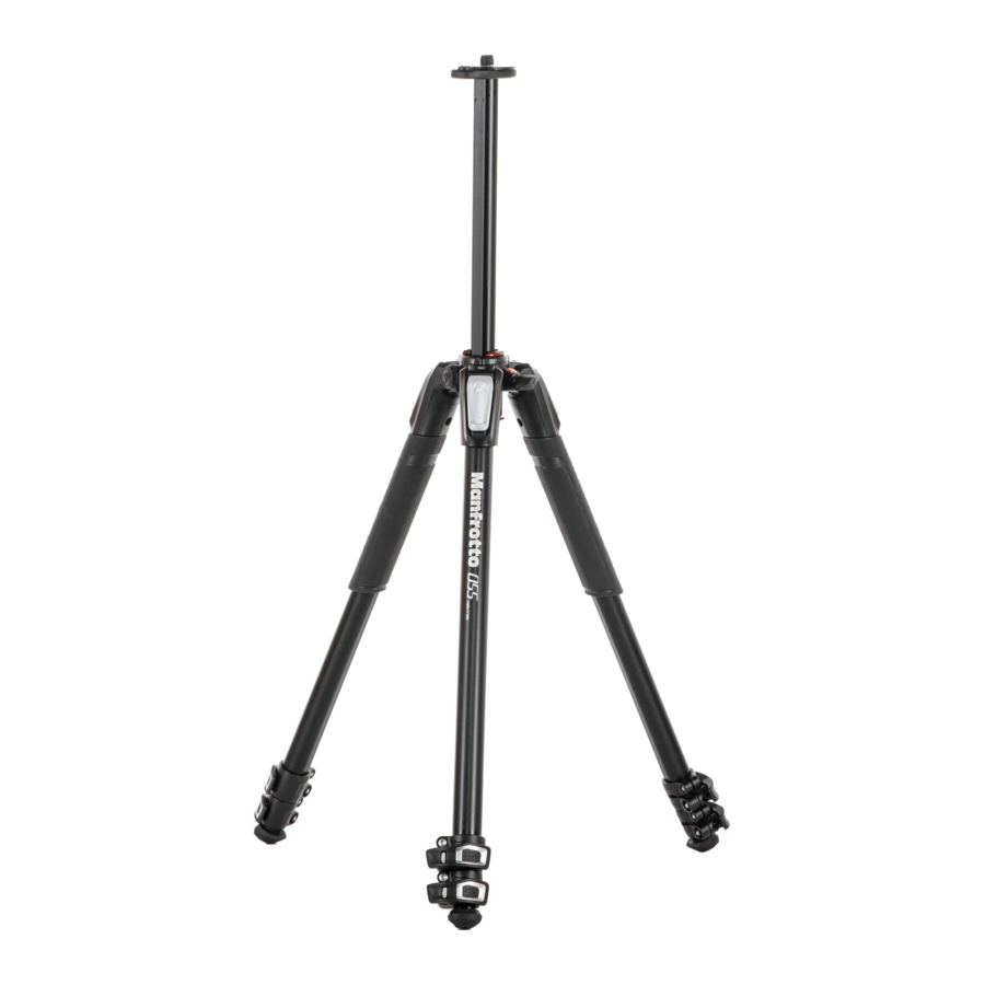
Designed for the advanced hobbyist and for the professional photographer, this is an extremely versatile tripod, ideal for small, medium format cameras, digital or conventional type.
KEY FEATURES:
- A unique sliding centre column that can be operated in either a vertical or horizontal plane.
- Each leg can be independently set at 4 angles of spread.
- Spirit level.
- Two rubber made leg warmers
- Easy link socket for inserting arms
- Quick Power Lock levers that allow to easily open all the levers simultaneously
- Hook for hanging a counterweight and for a strap
SET UP
Open the 3 tripod legs.
To adjust the height of the tripod, each leg has telescopic extensions that can be released by rotating lever "A" on the locking collar "B". Grab the levers with the whole palm of the hand. Simultaneously unlock all the locking levers.


TAKE CARE to avoid pinching your finger when opening the lever (see fig. 1A). When the required height is achieved, lock lever "A".
LEG ANGLE ADJUSTMENT

Each leg can be set at 4 angles of spread. To change the angle on a leg, close the leg towards the centre column slightly and pull down the locking button "C" at the top of the leg. Whilst holding the button down, select the new leg angle and then release button "C" to lock in position.
The angle of each leg can be adjusted independently of the other two legs.
The last position allows to achieve the floor level.
CENTER COLUMN HEIGHT ADJUSTMENT

To release the centre column "D", unlock knob "E" and adjust the height of the column as required. Tighten knob "E" to lock the column in position.
HORIZONTAL CENTER COLUMN
The sliding centre column can also be used in the horizontal plane: this not only allows the camera to be offset from the legs' position, it provides the simplest way possible to shoot from directly overhead:

- unlock knob "E" (4.1)
- push button "Y" and, at the same time, raise the center column "D" completely until the red shells pop out as shown in figure 4.2
- turn 90° center column "D" as shown in figure 4.3
- slide the center column "D" into the hole "W" and lock knob "E" (fig. 4.4)
VERTICAL CENTER COLUMN
In order to set up the center column in vertical position, proceed as follow:

- unlock knob "E" and pull out completely the center colum "D" as shown in figure 5.1
![warning]()
TAKE YOUR HAND OFF CENTRE
COLUMN "D" to avoid pinching your finger (see fig. 5.2) - keeping your other hand clear of column "D", push button "Y" with one hand (5.3)
- still keeping your other hand clear, with the same hand, rotate the center colum "D" in a vertical position as shown in figure 5.4
- rotate the column until the red arrow on the shells is aligned with the arrow on the casting, then push down the column
MOUNTING AND REMOVING A CAMERA HEAD
Remove the cap "Z" (fig.1)
Mount the camera head on the plate at the top of the centre column via the 3/8" mounting screw (screw head clockwise). Then raise the centre column and with a small screwdriver, tighten the screw "M" up against the base of the head, taking care not to force it. This unique feature works especially well with Manfrotto heads due to the specially designed base, which prevents the head unscrewing accidentally.
To remove the head, loosen the screw "M" and unscrew the head from the column counterclockwise).
LEVELLING

The tripod is supplied with a spirit level "H" to enable you to level the tripod.
The spirit level can be positioned as shown in figure 7 to guarantee max visibility and practicality.
NOTE

For outdoor use, especially in windy conditions, it is possible to stabilise the tripod: hang a counterweight (not supplied) on top of the hook "L"
TRANSPORTATION

The tripod has a hook "L" for optional carrying strap
LEG LOCK TENSION ADJUSTMENT

If the telescopic leg extensions slip even after having tightened the locking lever "A", the locking tension will need to be adjusted.
In order to do this:
- release lock lever "A"
- turn the screw "P" clockwise using the special key "N" provided on one of the tripod legs. Normally a third of a turn will be sufficient to achieve the correct locking tension.
ATTACHING ACCESSORIES
Remove cap "K"

The tripod has one 3/8" female thread "X" (fig. 11) which can be used to attach accessories, such as Manfrotto arms that can in turn support lights, monitors, etc.

Documents / ResourcesDownload manual
Here you can download full pdf version of manual, it may contain additional safety instructions, warranty information, FCC rules, etc.
Download Manfrotto MT055CXPRO3/CXPRO4/XPRO3, MT190CXPRO3/CXPRO4/XPRO3/XPRO4 - Tripod Manual
Advertisement
Thank you! Your question has been received!


Need Assistance?
Do you have a question about the MT055XPRO3 that isn't answered in the manual? Leave your question here.