Advertisement
INTRODUCTION
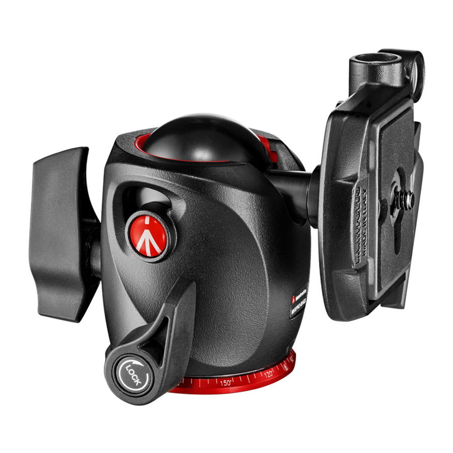
A professional ball head designed for medium-format cameras.
SET UP

Assemble the head on the tripod using 3/8" female thread "A".
 The top plate on Manfrotto tripods are equipped with three set screws "B" which clamp against the base of the head to ensure effective and secure locking.
REMOVE QUICK RELEASE PLATE FROM HEAD

To remove plate "G" it is necessary to open the lever "H".
The lever "H" can not be opened whilst the safety lever "I" is in closed position. To remove the safety catch, rotate the lever "H" and push down safety lever "I" until the lever "H" reaches the stop.
ASSEMBLING CAMERA ON PLATE

Fix the camera onto plate "G" by screwing home camera screw "M" into the camera's threaded hole WITHOUT APPLYING FORCE, using the ring "Q". Before fully locking, align the camera with the "LENS" marking on the plate "G".
Please ensure you have securely locked the camera on to the release plate before use.
MOUNTING THE CAMERA ON THE HEAD


Push the ring "Q" so that it is flat against the plate "G".
Insert the camera plate "G" (fig. 4) on top of the head until locking lever "H" clicks and closes.
Make sure that plate "G" (fig. 5) is fully locked by pushing lever "H" and checking that the camera is fitted securely to the head.
REMOVE THE CAMERA FROM THE HEAD

Whenever the camera needs to be removed from the head, hold the camera securely in one hand while rotating the lever "H" and push down safety lever "I" until the lever "H" reaches the stop.
USE
The head has panoramic and ball independent movements.
The lever "E" locks the panoramic movement.
To release the movement, unlock lever "E" by rotating anticlockwise.
Once the desired position is achieved, lock the head by turning lever "E" fully clockwise. The lever "C" locks the ball movement.
To ensure that the ball head is used safety, always hold the camera with one hand while releasing the ball.
To release the ball "D" for positioning the camera, unlock lever "C" by rotating anticlockwise. Once the desired position is achieved, lock the ball "D" by turning lever "C" fully clockwise.
The head incorporates a separate friction adjustment for the ball movement, which makes it easier to control the positioning of the head before locking it off. To adjust the friction ensures the ball "D" is not locked (rotating the locking lever "C" anticlockwise). Then hold the camera in one hand and rotate with the other the knob "F" clockwise to tighten the friction, anticlockwise to reduce the friction.
The friction does not allows the locking of the camera: we recommend to lock the ball "D" by fully turning the lever "C".

VideosManfrotto MHXPRO-BHQ2 - Xpro Ball Head Review Video
Documents / ResourcesDownload manual
Here you can download full pdf version of manual, it may contain additional safety instructions, warranty information, FCC rules, etc.
Download Manfrotto MHXPRO-BHQ2 - Xpro Ball Head Manual and Review Video
Advertisement


Need help?
Do you have a question about the MHXPRO-BHQ2 and is the answer not in the manual?
Questions and answers