Advertisement
INTRODUCTION

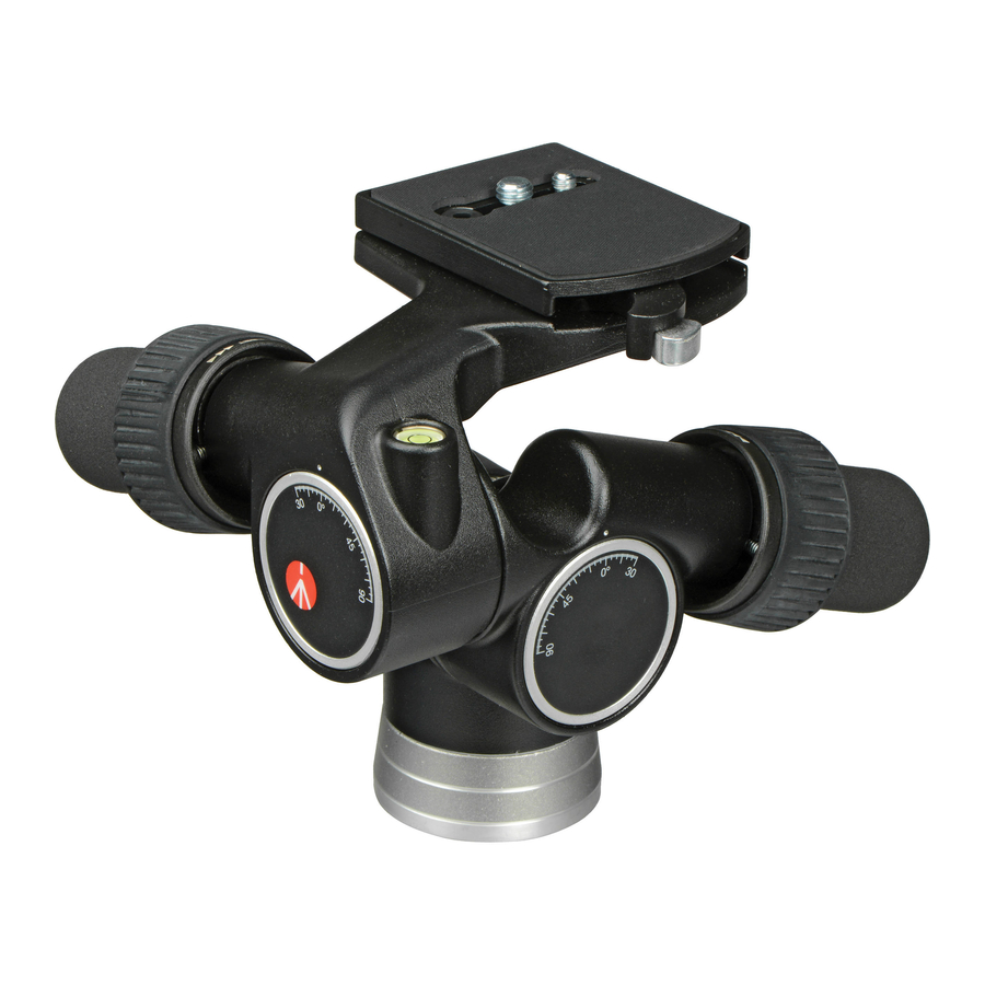
The head offers precise geared movement in three directions and is designed for 35mm SLR, medium and large format cameras
KEY FEATURES
- Ability to disengage the gear movement temporarily to rapidly set the camera in the general position required and then engage the geared movements for final adjustment
- Quick release plate with secondary security
- 1/4" and 3/8" camera screws
- 3 Spirit levels
SET UP
ASSEMBLING HEAD ON TRIPOD

Assemble the head on the tripod using 3/8" female thread "G".
The top plate on Manfrotto tripods are equipped with three set screws "V" which clamp against the base of the head to ensure effective and secure locking.
REMOVE QUICK RELEASE
PLATE FROM HEAD

The lever "N" is equipped with a safety button "O" to prevent the camera plate "I" from accidentally being released.
To release the camera plate "I":
- pull the locking lever "N" in the direction indicated by the arrow (fig. 2) until it will go no further
- hold lever "N" in the above position and at the same time press button "O" (fig. 3)
- this allows lever "N" to rotate further thus releasing the camera plate "I"
PLATE CAMERA SCREW

The quick release plate "I" is supplied with 1/4" "L" and 3/8" "H" camera screws.
To remove the unused screw:
- remove the rubber cap "M" by carefully pressing it out with one finger
- remove the screw "L" or "H"
- replace the rubber cap to prevent the screw being lost
The head has 1/4" and 3/8" holes for storing the unused screw.
ASSEMBLING
CAMERA ON PLATE

Fix the camera onto the plate "I" by screwing home the camera screw "H" or "L" into the Cameras' threaded hole WITHOUT APPLYING FORCE.
The screw "H" or "L" slides along the slit "R" allowing you to align the camera lens with the plate "I" and there by choose the best balance position.
Note: The screws "H" and "L" have a grove in the head to enable them to be tightened with a coin
Note: The plate "I" (fig. 1) has also 1/4" thread attachment "S" and 3/8" thread attachment "T"
MOUNTING THE CAMERA ON THE HEAD
 Insert the camera plate "I" (fig. 5) into the dovetail sides "U" on top of the head and then press plate "I" downwards until locking lever "N" clicks and closes.

Make sure that plate "I" (fig. 6) is fully locked by pushing lever "N" all the way to the left side and checking that the camera is fitted securely

REMOVE THE CAMERA FROM THE HEAD

Whenever the camera needs to be removed from the head, hold the camera securely in one hand while operating locking lever "N" and safety lever "O" with the other.
USE
FINE ADJUSTMENT
Use the following control knobs (fig. 1)
"A" = Pan
"B" = Tilt
"C" = Levelling
Fine adjustment is made by simply rotating the control knobs (fig. 8, 9 and 10)


The design of the geared mechanism enables the camera to be set in position without the need to lock off once the required angles are achieved
RAPID ADJUSTMENT
Use the following control rings (fig. 1)
"D" = Pan
"E" = Tilt
"F" = Levelling
Rapid adjustment can be made by using a hand to rotate the control wheel ("D", "E", "F") through 90° following the arrows (fig. 11).

While holding the control wheel open, the camera can be rapidly deployed with the other hand to the desired position. Release the control ring to lock the head in position. The head is supplied with 3 spirit levels: "P" for panning (fig. 8), "X" for vertical portrait format (fig. 9) and "Z" for horizontal position (fig. 10).

Documents / ResourcesDownload manual
Here you can download full pdf version of manual, it may contain additional safety instructions, warranty information, FCC rules, etc.
Advertisement
Thank you! Your question has been received!


Need Assistance?
Do you have a question about the 405 that isn't answered in the manual? Leave your question here.