Table of Contents
Advertisement
Quick Links
Register at www.Toro.com.
Original Instructions (EN)
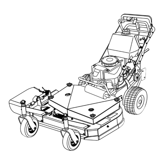
Commercial Walk-Behind Mower
Fixed Deck, T-Bar, Gear Drive with 32in, 36in
or 48in Cutting Unit
Model No. 30672—Serial No. 315000001 and Up
Model No. 30674—Serial No. 315000001 and Up
Model No. 30678—Serial No. 315000001 and Up
Model No. 39674—Serial No. 315000001 and Up
Form No. 3391-599 Rev A
G017538
*3391-599* A
Advertisement
Table of Contents

Related Manuals for Toro 30674


Summary of Contents for Toro 30674
- Page 1 Fixed Deck, T-Bar, Gear Drive with 32in, 36in or 48in Cutting Unit Model No. 30672—Serial No. 315000001 and Up Model No. 30674—Serial No. 315000001 and Up Model No. 30678—Serial No. 315000001 and Up Model No. 39674—Serial No. 315000001 and Up...
-
Page 2: Figure 1
Public Resource Code Section 4442 to use or operate the engine on any forest-covered, brush-covered, or You may contact Toro directly at www.Toro.com for product grass-covered land. Other states or federal areas may and accessory information, help finding a dealer, or to register have similar laws. -
Page 3: Table Of Contents
Contents Safety ................4 Figure 2 Safe Operating Practices........... 4 Toro Mower Safety ..........6 1. Safety alert symbol Slope Indicator ............7 Safety and Instructional Decals ......... 8 This manual uses 2 words to highlight information. Product Overview ............12 Important calls attention to special mechanical information Controls ...............12... -
Page 4: Safety
Safety Mower Deck Maintenance...........38 Servicing the Cutting Blades........38 Adjusting the Blade Brake........41 Note: The addition of attachments made by other Replacing the Grass Deflector ........42 manufacturers that do not meet American National Standards Storage ................42 Institute certification will cause noncompliance of this Troubleshooting ............44 machine. - Page 5 Operation Safe Handling of Fuels • Lightning can cause severe injury or death. If lightning • To avoid personal injury or property damage, use is seen or thunder is heard in the area, do not operate extreme care in handling gasoline. Gasoline is extremely the machine;...
-
Page 6: Toro Mower Safety
Keep all movement on slopes slow and gradual. Do not performance of your Toro equipment, count on Toro make sudden changes in speed or direction. genuine parts. When it comes to reliability, Toro delivers • Mow slopes side to side. -
Page 7: Slope Indicator
Slope Indicator G011841 Figure 3 This page may be copied for personal use. 1. The maximum slope you can safely operate the machine on is 20 degrees. Use the slope chart to determine the degree of slope of hills before operating. Do not operate this machine on a slope greater than 20 degrees. Fold along the appropriate line to match the recommended slope. -
Page 8: Safety And Instructional Decals
Safety and Instructional Decals Safety decals and instructions are easily visible to the operator and are located near any area of potential danger. Replace any decal that is damaged or lost. Manufacturer's Mark 1. Indicates the blade is identified as a part from the original machine manufacturer. - Page 9 98-5130 1. Warning—read the Operator's Manual for instructions on torquing the blade bolt/nut to 75-80 ft-lb (102-106 N⋅m). 98-3296 For Models with 2–Blade Mower Decks 106-5517 1. Warning—do not touch the hot surface. 98-4387 1. Warning—wear hearing protection. 106-5519 1. Severing hazard of hand or foot, mower 3.
- Page 10 126-1400 1. Warning—Read the Operator’s Manual. Use only Toro riding attachments. Use of other riding attachments may create a hazardous condition resulting in injury. 121-6049 1. Thrown object 3. Cutting/dismemberment hazard—keep bystanders hazard of hand or foot, away from the machine.
- Page 11 131-1180 1. Read the Operator's Manual. (A) Short, light grass; dry conditions; maximum dispersion; (B) Bagging setting; (C) Tall, dense grass; wet conditions; maximum ground speed...
-
Page 12: Product Overview
Controls Product Overview Become familiar with all the controls (Figure 5) before you start the engine and operate the machine. G017539 Figure 4 1. Side discharge 5. T-bar control 2. Mower deck 6. Handle 3. Recoil-start handle 7. Front caster wheel 4. -
Page 13: Specifications
Contact your Authorized Service Dealer or Close the fuel-shutoff valve when transporting or storing the Distributor or go to www.Toro.com for a list of all approved machine. attachments and accessories. -
Page 14: Operation
Operation DANGER In certain conditions during fueling, static Adding Fuel electricity can cause a spark, which can ignite the fuel vapors. A fire or explosion from fuel can burn • For best results, use only clean, fresh (less than 30 days you and others and can damage property. -
Page 15: Filling The Fuel Tank
Filling the Fuel Tank Setting the Parking Brake 1. Pull the upper control bar rearward and hold it in this 1. Shut the engine off and set the parking brake. position (Figure 2. Clean around the fuel-tank cap and remove the cap. 2. -
Page 16: Operating The Blade-Control Lever (Pto)
Operating the Blade-Control Note: Allow the rope to recoil slowly. Lever (PTO) Important: Do not pull the recoil rope to its limit or release the starter handle when you pull out The blade-control lever (PTO) engages and disengages power the rope because the rope may break or the recoil to the mower blades. -
Page 17: The Safety-Interlock System
The Safety-Interlock System 2. Release the parking brake; refer to Releasing the Parking Brake (page 15). CAUTION 3. Slowly press on the upper control bar to move forward (Figure 10). If safety-interlock switches are disconnected or To go straight, apply equal pressure to both ends of the damaged the machine could operate unexpectedly, upper control bar (Figure... -
Page 18: Stopping The Machine
Driving Forward up a Curb Note: Lifting up on the lower handle will assist driving the machine up a curb and not spin the drive wheels. 1. Disengage the mower blades. 2. Select the first gear to drive the machine. 3. -
Page 19: Adjusting The Flow Baffle
Adjusting the Flow Baffle You can adjust the mower discharge flow for different types of mowing conditions. Position the baffle to give the best quality of cut. 1. Disengage the PTO, move the motion control levers to the neutral locked position and set the parking brake. 2. -
Page 20: Side Discharging Or Mulching The Grass
adjustment range, in 6 mm (1/4 inch) increments, of cutting height in any axle position. Use the same number of blade spacers on all blades to achieve a level cut (2 above and 2 below, 1 above and 3 below, etc.). 1. -
Page 21: Adjusting The Handle Height
Adjusting the Axle Height Adjust the axle position to the selected height-of-cut setting. Refer to the Height-of-Cut Chart. 1. Disengage the blade control (PTO) lever and set the parking brakes. 2. Stop the engine and wait for all moving parts to stop before leaving the operating position. -
Page 22: Adjusting The Control Rods
Figure 21 1. Upper handle 4. Locknut (3/8 inch) g018809 2. Rear frame 5. Upper mounting hole Figure 22 6. Lower mounting hole 3. Flange bolt (3/8 x 1 inch) 4. Upper control bar 1. 25 to 32 mm (1 to 1-1/4 inches) gap 3. -
Page 23: Height-Of-Cut Chart
Height-of-Cut Chart Number of spacers below Number of 1/4 inch blade spacers below the spindle the caster 13 mm 5 mm Axle (1/2 inch ) (3/16 inch) position 26 mm 32 mm 38 mm 45 mm 51 mm (1 inch) (1-1/4 inch) (1-1/2 inch) (1-3/4 inch) -
Page 24: Maintenance
Maintenance Note: Determine the left and right sides of the machine from the normal operating position. Recommended Maintenance Schedule(s) Maintenance Service Maintenance Procedure Interval • Change the engine oil. After the first 8 hours • Check the mower belt tension. •... -
Page 25: Lubrication
Lubrication Grease Type: #2 general-purpose lithium-based or molybdenum-based grease Lubricating the Machine 1. Disengage the PTO and set the parking brake. 2. Stop the engine, remove the key, and wait for all moving parts to stop before leaving the operating position. Figure 24 3. -
Page 26: Engine Maintenance
Engine Maintenance 2. Dry the element by squeezing it in a clean cloth. Important: Replace the foam element if it is torn or worn. Servicing the Air Cleaner Servicing the Paper Air-Cleaner Service Interval: Every 25 hours—Clean the foam air-cleaner element. Element Every 50 hours—Check the paper air-cleaner element. - Page 27 Checking the Engine-Oil Level Changing the Engine Oil 1. Park the machine on a level surface. 1. Park the machine so that the drain side is slightly lower than the opposite side to ensure that the oil drains 2. Disengage the PTO and set the parking brake. completely.
-
Page 28: Servicing The Spark Plugs
Figure 31 1. Oil filter 2. Adapter Figure 32 1. Spark-plug wire/spark plug 3. Apply a thin coat of new oil to the rubber gasket on the replacement filter (Figure 31). 4. Clean around the spark plugs to prevent dirt from 4. -
Page 29: Fuel System Maintenance
Installing the Spark Plugs Fuel System 1. Install the spark plugs and the metal washer. Ensure Maintenance that the air gap is set correctly. 2. Tighten the spark plugs to 22 N-m (16 ft-lb). Servicing the Fuel System 3. Connect the wires to the spark plugs (Figure 33). - Page 30 Replacing the Fuel Filter Service Interval: Every 200 hours/Yearly (whichever comes first) Never install a dirty filter if it is removed from the fuel line. Note: Note how the fuel filter is installed in order to install the new filter correctly. Note: Wipe up any spilled fuel.
-
Page 31: Drive System Maintenance
Drive System Cooling System Maintenance Maintenance Checking the Tire Pressure Cleaning the Air-Intake Screen Service Interval: Every 50 hours/Monthly (whichever Before each use, remove any buildup of grass, dirt, or comes first) other debris from the cylinder and cylinder-head cooling fins, the air-intake screen on the flywheel end, and the Maintain the air pressure in the rear tires at 83 to 97 kPa (12 carburetor-governor levers and linkage. -
Page 32: Brake Maintenance
Brake Maintenance 3. Check the brake before you adjust it; refer to Checking the Brakes (page 32). 4. Release the parking brake; refer to Releasing the Servicing the Brakes Parking Brake (page 15). 5. To adjust the brake, rotate the wing nuts on the brake Before each use, check brakes on both a level surface and rods (Figure... -
Page 33: Belt Maintenance
Belt Maintenance 4. Remove the mower belt (Figure 41). Checking the Belts Service Interval: Every 50 hours/Monthly (whichever comes first)—Check the belts. Check the belts for cracks, frayed edges, burn marks, wear, signs of overheating, or any other damage. Replace any damaged belts. - Page 34 Note: The proper mower belt tension is 44 to 67 N-m (10 to 15 ft-lb) with the belt deflected 13 mm (1/2 inch) halfway between the pulleys (Figure 45 Figure 46). 8. Engage the blade-control (PTO) lever. 9. Check the clearance between the bell crank and the transmission output shaft (Figure 42).
-
Page 35: Adjusting The Mower Belt Tension
necessary. The disengaged belt should not drag or fall off the pulley when the guides are properly adjusted. Adjusting the Mower Belt Tension Adjusting the Tension for 32in and 36in Mower Decks Service Interval: After the first 8 hours—Check the mower belt tension. - Page 36 positioned to the middle or front hole (Figure 48). Use the hole that will give the correct adjustment. When you move the idler pulley, you must move the belt guide. Move the belt guide to the front position (Figure 48). g017651 Figure 46 Figure 48...
- Page 37 Adjusting the PTO Engagement Linkage The PTO engagement linkage adjustment is located beneath the front left-hand corner of the engine deck. 1. Disengage the blade-control (PTO) lever and set the parking brakes. 2. Stop the engine and wait for all moving parts to stop before leaving the operating position.
-
Page 38: Mower Deck Maintenance
Mower Deck Maintenance Servicing the Cutting Blades To ensure a superior quality of cut, keep the blades sharp. For convenient sharpening and replacement, you may want to keep extra blades on hand. WARNING g017650 Figure 52 A worn or damaged blade can break, and a piece of the blade could be thrown into the operator's 1. - Page 39 Replace the blades if you hit a solid object or if the blades are out of balance or bent. To ensure optimum performance and continued safety conformance of the machine, use genuine Toro replacement blades. Replacement blades made by other Figure 54 manufacturers may result in non-conformance with safety standards.
- Page 40 balanced, file some metal off the end of the sail area only (Figure 59). Repeat this procedure until the blade is balanced. Figure 59 1. Blade 2. Balancer Installing the Blades 1. Install the curved washer and then the blade onto the bolt.
-
Page 41: Adjusting The Blade Brake
Adjusting the Blade Brake 1. Disengage the PTO, turn the ignition key to the off position, and remove the key. 2. Wait for all moving parts to stop before leaving the operating position and setting the parking brake. 3. If necessary, adjust the spring mounting bolts so that the blade-brake pad rubs against both sides of the pulley groove (Figure... -
Page 42: Replacing The Grass Deflector
Replacing the Grass Deflector Storage WARNING 1. Disengage the power take-off (PTO), set the parking brake, turn the ignition key to the Off position, and An uncovered discharge opening could allow the remove the key. lawn mower to throw objects in the operator's or 2. - Page 43 10. Check and tighten all bolts, nuts, and screws. Repair or replace any part that is damaged or worn. 11. Paint all scratched or bare metal surfaces with paint available from your Authorized Service Dealer. 12. Store the machine in a clean, dry garage or storage area. Remove the key from the ignition switch and keep it in a memorable place.
-
Page 44: Troubleshooting
Troubleshooting Problem Possible Cause Corrective Action The engine will not start, starts hard, or 1. The fuel tank is empty. 1. Fill the fuel tank with gasoline. fails to keep running. 2. The fuel-shutoff valve is closed. 2. Open the fuel-shutoff valve. 3. - Page 45 Problem Possible Cause Corrective Action The blades do not rotate. 1. The mower deck belt is worn or loose. 1. Check the belt tension. 2. The mower deck belt is broken. 2. Install a new deck belt. 3. The mower deck belt is off pulley. 3.
-
Page 46: Schematics
Schematics Electrical Schematic (Rev. -A) - Page 47 Notes:...
- Page 48 Customers who have purchased Toro products outside the United States or Canada should contact their Toro Distributor (Dealer) to obtain guarantee policies for your country, province, or state. If for any reason you are dissatisfied with your Distributor's service or have difficulty obtaining guarantee information, contact the Toro importer. If all other remedies fail, you may contact us at Toro Warranty Company.