Table of Contents
Advertisement
Quick Links
Advertisement
Table of Contents

Related Manuals for Toro 25450A


Summary of Contents for Toro 25450A
- Page 1 Form No. 3395-823 Rev A RT1200 Traction Unit Model No. 25450—Serial No. 315000001 and Up Model No. 25450A—Serial No. 315000001 and Up Model No. 25450C—Serial No. 315000001 and Up Model No. 25450W—Serial No. 315000001 and Up *3395-823* A Register at www.Toro.com.
- Page 2 Whenever you need service, genuine Toro parts, or additional information, contact an Authorized Toro Service Dealer Figure 1 or Toro Customer Service and have the model and serial numbers of your product ready. Figure 1 illustrates the 1. Location of the model and serial number plate location of the model and serial numbers on the product.
-
Page 3: Table Of Contents
Contents Safety ................4 Figure 2 Before Operating the Machine ........5 Electrical Line Safety ..........7 1. Safety alert symbol Gas Line Safety ............7 Communication Line Safety........7 This manual uses 2 words to highlight information. Water Line Safety ............ 7 Important calls attention to special mechanical information Safety and Instructional Decals ......... -
Page 4: Safety
Preparing to Disconnect the Components....75 standards and with the instructions in this Operator’s Disconnecting the Alternator Wiring......75 Manual. Modifications to this machine should be made Disconnecting the Computer-module only by an Authorized Toro Service Dealer. Connectors ............76 Connecting the Computer-module WARNING Connectors ............76 Welding, cutting, or drilling parts of the machine Connecting the Alternator Wiring......76... -
Page 5: Before Operating The Machine
Evaluate the terrain to determine what accessories and • attachments are needed to properly and safely perform Use only Toro-approved attachments. Attachments can change the stability and the operating characteristics of the job. Use only accessories and attachments approved by the manufacturer. - Page 6 ROPS has been in an accident. – Do not remove the fuel cap or add fuel when the • Replace a damaged ROPS using only genuine Toro engine is running. Allow the engine to cool before replacement parts; do not repair or modify the ROPS.
-
Page 7: Electrical Line Safety
Gas Line Safety • Battery gases can explode. Keep cigarettes, sparks, and flames away from the battery. • Keep your body and hands away from pinhole leaks WARNING or nozzles that eject high-pressure hydraulic fluid. Use cardboard or paper to find hydraulic leaks; never use If you damage a gas line, an immediate explosion your hands. -
Page 8: Safety And Instructional Decals
Safety and Instructional Decals Safety decals and instructions are easily visible to the operator and are located near any area of potential danger. Replace any decal that is damaged or lost. Figure 4 1. Decal 125-6689 7. Decal 130-7541 (2 decals, 1 on each side) 2. - Page 9 Figure 5 1. Decal 125-8496 7. Decal 125-4963 2. Decal 125-8473 (on the floor panel covering the battery) 8. Decal 127-1829 3. Decal 125-8495 9. Decal 125-8480 4. Decal 127-1828 10. Decal 125-6157 (under the left-side cowl) 5. Decal 125-6139 11.
- Page 10 125–6135 125-6157 1. Disconnect the battery 3. On/Start power. 125–6139 2. Off/Stop 4. Read the Operator’s Manual. 1. Lift point; tie down point 125-6671 1. Explosion hazard; electric shock hazard—call local utilities before digging.
- Page 11 125-8479 125-6689 1. Burn hazard from contents under pressure—read the Operator’s Manual. 1. Warning—keep away from 2. Cutting/dismemberment hot surfaces. hazard, fan—keep away from moving parts; keep all guards and safety devices in place. 125-8480 1. Warning—do not climb on ROPS. 125-6694 1.
- Page 12 125-8499 1. Warning—read the 3. Forward 125-8482 Operator's Manual. 1. Hydraulic return 2. Reverse 4. Transmission—gear selection 125–8483 130-7541 1. Hydraulic fluid; read the Operator’s Manual. 1. Warning—keep bystanders away from the machine. 131-0439 1. Differential—lock 2. Differential—unlock 125-8484 1. 12-volt receptacle...
- Page 13 125-8495 1. Tilt the machine left 6. Sideshift—left (optional 11. Auxiliary hydraulic (optional 16. Trencher—fast rotation attachment) kit) (optional accessory) 2. Tilt the machine right 7. Lower the crumber/rotate 12. Vibratory plow depth—float 17. Trencher—slow rotation the plow forward (optional on (optional accessory) (optional accessory) attachment)
- Page 14 127-1828 1. Hydraulic pressure 4. Raise the attachment. 2. Lower the attachment. 5. Hydraulic return 3. Case drain 127-1829 130-7539 1. Oil drain 1. Electrical power 3. Engine—run 2. Engine—stop 4. Engine—start 131-0440 1. Parking brake—engage 2. Parking brake—disengage...
- Page 15 130-7540 1. Warning—read the Operator's Manual. 4. Warning—keep bystanders away from 7. Explosion hazard; electric shock the machine. hazard—before digging call the local utilities service. 2. Warning—do not operate the machine 5. Warning—keep away from moving 8. Read the Operator's Manual for unless you have received instruction.
-
Page 16: Product Overview
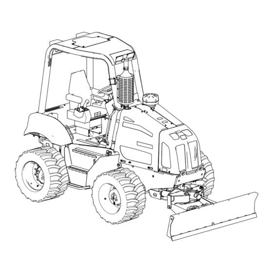
Product Overview Figure 7 1. Nose panel 5. Backfill blade 2. Left side panel 6. Fuel reservoir 3. Grab handles 7. Fuel cap 4. ROPS enclosure 8. Steps Figure 8 1. Grab handles 4. Steps 2. Right side panel 5. Hydraulic-fluid sight gauge 3. -
Page 17: Controls
Controls Throttle Button • Throttle-up Button—Press the throttle-up button Become familiar with all the controls (Figure 9 through Figure (button 7), located at the bottom-right corner of the 16) before you start the engine and operate the machine. command center, to increase the engine speed (Figure Note: Press the button repeatedly to increase the engine Command Center... -
Page 18: Traction-Control Cluster
Key Switch Use the key switch to power the electrical accessories, start the machine, and stop the machine (Figure 11). The 4 key-switch positions are as follows: • Accessory—Rotate the key switch to this position to energize the lamp switch circuits. •... -
Page 19: Attachment-Control Cluster
• • Move the utility-traction joystick forward to move the Move the joystick to the left to tilt the backfill blade to the machine forward (Figure 14). left, or move the joystick to the right to tilt the backfill blade to the right (Figure 15). -
Page 20: Operator Seat And Seat Belt
• Move the joystick rearward to start the vibration of the plow blade (Figure 15). • Move the joystick further rearward to increase the vibration (Figure 15). • Move the joystick toward the Neutral position to decrease and stop the vibration (Figure 15). - Page 21 Seat-Height and Seat-Slide Buttons – Rotate the lever for the weight compensator counterclockwise to reduce the support tension of the seat. Armrest-Height Control Rotate the armrest-height control to raise or lower the armrest (Figure 17). Seat-Lumbar Knob Rotate the seat-lumbar knob, found behind the seat, to adjust the back lumbar support for best comfort (Figure 17).
-
Page 22: Specifications
G009027 its capabilities. Contact your Authorized Service Dealer or Figure 19 Distributor or go to www.Toro.com for a list of all approved attachments and accessories. 2. Wear hearing protection. 1. Wear safety glasses. -
Page 23: Preparing For Work
Preparing for Work Using summer-grade fuel above 20° F (-7°C) contributes toward a longer fuel pump life and increased power compared Before operating the machine on the job site, review the to using winter-grade fuel. following items: WARNING • Gather all relevant information available about the job site before you begin working. - Page 24 Using Biodiesel Fuel This machine can also use a biodiesel blended fuel of up to B20 (20% biodiesel, 80% petrodiesel). The petrodiesel portion should be low or ultra-low sulfur. Observe the following precautions: • The biodiesel portion of the fuel must meet specification ASTM D6751 or EN14214.
-
Page 25: Checking The Engine-Oil Level
-5°C (23°F). However, continuous use of low-viscosity oil can decrease engine life. Toro Premium Engine Oil is available from an Authorized Toro Service Dealer in either 15W-40 or 10W-30 viscosity with API classification CJ-4 or higher. See the Parts Catalog for part numbers. -
Page 26: Checking The Coolant Level In The Reservoir
Checking the Coolant Level in the Reservoir Service Interval: Before each use or daily If the engine overheat warning is displayed on the control panel, check the coolant level in the reservoir and add coolant if it is low. Also inspect the engine compartment around the radiator and clear away any obstructions to air flow. -
Page 27: Checking The Hydraulic-Fluid Level
One bottle is sufficient for 15.1 to 22.7 L (4.0 to 6.0 US gal) of hydraulic fluid; you can order this additive from an Authorized Toro Service Dealer. 1. Park the machine on a level surface, and put all the attachments in the transport position. -
Page 28: Operating The Command Center
• Check the machine for broken, damaged, loose, or missing parts. Replace, tighten, or adjust these parts before you operate the machine. • Repair or replace all damaged ROPS and seat belt parts. Operating the Command Center Software Messages The command center will display information about the controller version, display version, and installed optional attachments or kits that are operated through the command center. - Page 29 Note: If the indicator goes into the red area, reduce the engine speed to idle for a few minutes to allow the engine to cool, then stop the engine. Check the coolant level, for debris on the radiator, or for a thermostat that does not operate correctly.
- Page 30 Figure 34 Figure 33 1. Wait-to-start-engine indicator 1. Machine or engine error 4. Check alternator or battery 2. Low engine-oil pressure 5. Engine overheated (flashes) (flashes) Reading the Machine or Engine Error Indicators in the 3. High hydraulic-oil 6. Low fuel quantity (flashes) Command Display temperature (flashes) Note: When a warning indicator is shown in the command...
- Page 31 1. Return to the previous screen Accessing the Trencher Setup Function Screen Note: You need the PIN to access this screen; to obtain the PIN, contact an Authorized Toro Distributor. Use the trencher setup screen to access calibration settings for the following functions: •...
- Page 32 Figure 39 Accessing the Engine Errors Information Screen Use the trencher diagnostic screen (Figure 40) view suspect Figure 38 part number—failure mode identifier (SPN-FMI) codes for the engine; contact an Authorized Service Dealer. 1. Display brightness 3. Increase brightness indicator 2.
- Page 33 Using the PIN screen Note: This procedure requires that you have the PIN number, which you can obtain from an Authorized Service Dealer. Note: To access the trencher setup function for the machine, you must enter the unique 8-digit identification number assigned into the PIN screen.
-
Page 34: Operating The Engine
Operating the Engine air is at the proper temperature for starting the engine, the wait-to-start indicator in the display turns off. 2. Turn the key switch to the Start position. Before Starting the Engine Note: If the engine starts and then stops, do not 1. -
Page 35: Operating The Machine In Extreme Conditions
Operating the Machine in Extreme Conditions Both hot and cold weather place unusual demands upon the machine and the attachments. You can minimize temperature-related problems on the machine by performing the following steps: Operating the Machine in Hot Weather 1. Clean all dirt and debris from the radiator, heat exchanger, hydraulic-fluid cooler, and engine area to Figure 43 ensure that there is proper air flow to cool the engine. -
Page 36: Operating The Parking Brake
Driving and Stopping the 4. Check the coolant mixture before you operate the machine in cold weather. Use only a 50% ethylene Machine glycol and 50% water mixture in the cooling system year round. Using the Traction-Control Pedal 5. Before operating the machine, move it at low speed and actuate each hydraulic control several times to The traction-control pedal controls the direction and the warm the oil. - Page 37 Steering the Machine Using the Front-wheel Steering Use the steering wheel to control the front-wheel steering (Figure 46). Note: The front-wheel steering and rear-wheel steering operate independently (unless the machine is equipped with the optional advanced steering control). Figure 47 1.
-
Page 38: Operating The Transmission
Important: If you must temporarily park the Gear Machine Task machine on a slope or an incline, position the Selection machine at a right angle to the slope, with the Trenching, hard plowing, and boring front of the machine toward the bottom of the hill. Light trenching and backfilling Ensure that the machine is behind an object that will not move. -
Page 39: Preparing To Operate The Machine
Installing the Tilt-lockout Pin 1. Use the tilt switch to align the hole in the chassis-lockout bracket with the holes in the axle-lockout bracket (Figure 49). 2. Remove the hairpin from the tilt-lockout pin (Figure 50). Note: The tilt-lockout pin should be stowed in the vertical hole in the axle-lockout bracket. -
Page 40: Using The Backfill Blade
Note: You must sit in the operator seat before you move the machine; otherwise, the machine will not move. Note: The utility-traction lever controls the speed of the machine. The farther that you move the lever from the Neutral position, the faster the machine moves. Important: Control the speed of the machine travel with the utility-traction lever, not the throttle. -
Page 41: Using The Power Port
• To angle the backfill blade to the left: Press the left 8. Stop the engine and remove the key. half of the thumb control (Figure 57). 9. Fasten the front and rear of the machine to the trailer • To angle the backfill blade to the right: Press the using chains and a binder (Figure... -
Page 42: Completing The Work For The Day
Completing the Work for the When you complete your work for the day, do the following: 1. Backfill the spoils in the part(s) of the trench in which you are finished working. 2. Move the machine to a safe and stable location. 3. -
Page 43: Maintenance
Maintenance Recommended Maintenance Schedule(s) Maintenance Service Maintenance Procedure Interval • Check the oil level in the wheel hubs. After the first 100 hours • Check the oil level in the front and rear axles. • Change the oil in the wheel hubs. After the first 200 hours •... -
Page 44: Premaintenance Procedures
If you do not understand the service procedures 2. Connect the grease gun to the grease fittings for the for this machine, contact an Authorized Toro upper and lower pivots; apply 2 or 3 pumps of grease Service Dealer or obtain the service manual for this... - Page 45 Greasing the Front and Rear Drive Shafts Service Interval: Every 500 hours 1. Clean the grease fittings with a rag. 2. Connect the grease gun to the grease fitting for the slide coupling at the forward end of the drive shaft, and apply 2 or 3 pumps of grease to the fitting (Figure 62).
-
Page 46: Engine Maintenance
Engine Maintenance Before maintaining the engine, perform the following steps: 1. Park the machine on level ground, lower all attachments, and stop the engine. 2. Remove the ignition key and allow the engine to cool for 2 or 3 minutes. Accessing the Engine Figure 63 Removing the Side Panels... - Page 47 Installing the Side Panels 1. Align the side panel with the machine frame. 2. Align the mounting bolt at the top of the side panel with the hole in the support flange of the hood panel (Figure 67). Figure 67 Figure 65 1.
-
Page 48: Servicing The Engine Oil And Filter
-5°C (23°F). However, continuous use of low viscosity oil can decrease engine life because of wear. Toro Premium Engine Oil is available from an Authorized Toro Service Dealer in either 15W-40 or 10W-30 viscosity with API classification CH-4 or higher. See the Parts Catalog for part numbers. -
Page 49: Checking The Crankcase Breather Tube
(page 47). 4. Inspect the tube for cracks or damage; replace a cracked or damaged tube; refer to an Authorized Toro Dealer. Filling the Engine with Oil 1. Remove the oil-fill cap from the valve cover by rotating the cap and pulling it upward (Figure 69). -
Page 50: Checking The Charge-Air Piping
Checking the Charge-air Checking the Air-intake Piping Piping Service Interval: Before each use or daily—Check the air-intake piping for wear, damage, and Service Interval: Every 250 hours loose fasteners. Every 250 hours—Check the air-intake piping for Inspect the charge-air piping and hoses (Figure 73) for leaks, wear, damage, and loose fasteners. -
Page 51: Fuel System Maintenance
Fuel System Maintenance Servicing the Fuel System Draining Water from the Fuel Tank Service Interval: Before each use or daily 1. Stop the engine. 2. Place a drain pan under the drain plug in the fuel tank. Figure 75 3. Unscrew the drain plug from the fuel tank and drain the water (Figure 76). - Page 52 3. Install a new breather into the pipe coupling hand tight (Figure 78). 4. Install the right side panel; refer to Installing the Side Panels (page 47). Replacing the Fuel Filters Service Interval: Every 500 hours The engine on this machine uses a dual fuel-filter system, with a primary fuel filter and a secondary fuel filter.
- Page 53 • Read the engine owner’s manual for the proper bleeding procedure or contact your Authorized Figure 80 Toro Service Dealer. 1. Secondary fuel filter 2. Filter adapter (secondary fuel filter) Prime the fuel system to remove air from the system after the following events: •...
-
Page 54: Electrical System Maintenance
Authorized 1. Align the holes in the mounting flanges for the battery Toro Service Dealer for assistance. cover with the plate nuts in the ROPS platform around 8. If the engine does not start, pump the priming pump... - Page 55 Servicing the Battery Connecting a Booster Battery WARNING WARNING Exposure to battery acid or a battery explosion can Charging the battery produces gasses that can cause serious personal injury. explode. Before you service a battery, always wear face Never smoke near the battery and keep sparks and protection, protective gloves, and protective flames away from battery.
-
Page 56: Replacing A Fuse
6. Connect the negative (-) jumper cable to a ground 4. Connect the battery charger to the electrical source. point, such as the nut at the pivot point for the Important: Do not overcharge the battery. alternator (Figure 83). Note: Charge the battery as shown in the following 7. -
Page 57: Drive System Maintenance
Drive System Maintenance Servicing the Tires WARNING Exploding tires and/or rim parts can cause injury Figure 86 or death. 1. Hex-flanged bolts (5/16 x 4. Fuse block Keep yourself and others out of the area of danger. 3/4 inch) Stand on the tread side of the tire. Always fill 2. - Page 58 Note: Before you add air, ensure that the tire is properly installed on the machine, or put the wheel in a restraining device, such as a tire inflation cage. 2. Remove the cap from the valve stem. 3. Attach the self-locking chuck of the air hose to the valve stem.
-
Page 59: Servicing The Axles
Servicing the Axles Changing the Oil in the Wheel Hubs Service Interval: After the first 200 hours Hub-and-axle oil specification: Mobilfluid 424 Every 1,000 hours Checking the Oil Level in the Wheel Wheel hub oil capacity: approximately 1.5 L (1.6 US qt) Hubs Note: If possible, change the oil when it is warm. - Page 60 Checking the Oil Level in the Axles Service Interval: After the first 100 hours Every 250 hours 1. Place a drain pan under the pinion housing of the axle. 2. Remove the plugs from the sight port in the pinion housing of the axle (Figure 91 Figure...
- Page 61 Figure 93 Front Axle 1. Drain plug 3. Drain port 2. Drain pan 4. Front-axle housing Figure 95 Front Axle 1. Front-axle housing 4. Pinion housing 2. Oil-servicing equipment 5. Sight port 3. Fill plug Figure 94 Rear Axle 1. Drain plug 3.
-
Page 62: Servicing The Transmission
Servicing the Transmission 6. Fill the axles with the specified oil through the sight port until the oil is level with the threads at the bottom Transmission-oil specification: Mobilfluid 424 of the port (Figure 95 Figure 96). 7. Wait a few minutes for the oil to settle, then add more Checking the Oil Level in the oil as necessary. - Page 63 Changing the Transmission Oil 3. Apply PTFE thread sealing tape to the threads of the plug. Service Interval: Every 1,000 hours 4. Fill the transmission with the specified oil through the fill port (Figure 101). Draining the Transmission Oil Important: When you fill the transmission with Note: If possible, drain the oil when it is warm.
- Page 64 Changing the Transmission Filter 9. Check the transmission oil level; if the level is low, add the specified oil to the transmission; refer to Filling the Service Interval: Every 500 hours Transmission with Oil (page 63). Note: You can access the transmission filter from underneath Important: When you fill the transmission with the right side of the machine, inboard of the hydraulic tank.
-
Page 65: Cooling System Maintenance
Cooling System 2. Allow the engine to cool. 3. Remove the left side panel; refer to Removing the Side Maintenance Panels (page 46). 4. Check the coolant level by looking at the sight gauge in Servicing the Cooling System the side of the surge tank (Figure 103). - Page 66 Checking the Condition of Cooling System Components Service Interval: Every 300 hours Check the condition of the cooling system for leaks, damage, dirt, and loose hoses, and clamps. Clean, repair, tighten, and replace the components as necessary. Checking the Concentration of the Coolant Service Interval: Every 1,000 hours Test the concentration of ethylene glycol based antifreeze in...
- Page 67 Note: Dispose of the used coolant properly according to local codes. Figure 106 1. Drain valve 9. Close the drain valve (Figure 106). Figure 107 10. Remove the drain hose and clamp (Figure 104 Figure 105). 1. Reservoir door 3. Funnel 2.
- Page 68 D. Open the drain valve and drain the cleaning cooling system properly can damage both the engine solution into a drain pan (Figure 104 Figure and the cooling system. 106). 1. Remove the radiator cap from the recovery tank E. Close the drain valve (Figure 106).
-
Page 69: Belt Maintenance
Belt Maintenance Servicing the Engine Drive Belt WARNING Stop the engine and remove the key from the key switch before you begin to perform any maintenance or repair work. WARNING Figure 111 Contacting a rotating belt can cause serious injury or death. -
Page 70: Hydraulic System Maintenance
Hydraulic-fluid specification: Toro Premium All-season Hydraulic Fluid Draining the Hydraulic Reservoir If Toro Premium All-season Hydraulic Fluid is not available, Note: Drain the hydraulic fluid reservoir when the fluid is you may use Mobil DTE 15M Special (Mobil DTE 15M fluid warm, if possible. - Page 71 Figure 113 1. Fill cap 3. Plug 2. Sight gauge (hydraulic 4. Drain pan reservoir) Figure 114 7. Remove the drain plug from the hydraulic reservoir (located underneath the reservoir), and drain the 1. Fill level (midpoint) 3. Hydraulic fluid reservoir (Figure 113).
- Page 72 Changing the Hydraulic Filters Removing the Traction-pedal Assembly Remove the traction-pedal assembly as follows: 1. Remove the 4 hex-flanged head bolts that secure that traction-pedal assembly to the chassis of the machine (Figure 115). Figure 116 1. Container suitable for 3.
- Page 73 Note: Use a tapered-center punch or awl to puncture 12. Install the traction-pedal assembly; refer to Removing the Traction-pedal Assembly (page 72). the filter case. 3. Rotate the hydraulic-return filter counterclockwise and Installing the Traction-pedal Assembly remove the filter (Figure 117).
-
Page 74: Rops Maintenance
27 to 34 N-m (20 to 25 in-lb); refer to Figure 118. Note: Age, weather, and accidents cause damage to the ROPS and ROPS parts. If you have any doubts about the ROPS system, contact an Authorized Toro Service Dealer. -
Page 75: Welding On The Machine
Welding on the Machine 5. Using the finger pulls, lift the battery cover up to remove it from the ROPS platform (Figure 120). Important: Before you use an electric welder to repair 6. Remove the lock-washer nut (3/8 inch) securing the or modify the machine, perform all the following: negative-battery cable and ring terminal to the negative •... -
Page 76: Disconnecting The Computer-Module Connectors
2. Disconnect the 50-socket connector (CPU 1) from the back of the computer module (Figure 124). Figure 122 1. Charge wire 3. 4-socket connector Figure 124 (voltage-sense wire) 1. Forward 3. Computer module 2. Boot 2. 50-socket connector (CPU 4. 38-socket connector (CPU-2) 2. -
Page 77: Closing The Machine
Cleaning 5. Align the boot of the charge wire over the terminal and stud (Figure 122). Removing Dirt and Debris from Closing the Machine the Machine 1. Assemble the positive-battery cable into the positive stud of the battery (Figure 121) with the lock-washer Important: Operating the engine with blocked screens, nut (3/8 inch) that you removed in step Preparing... -
Page 78: Storage
B. Clean the battery, terminals, and posts with a wire brush and baking soda solution. C. Coat the cable terminals and battery posts with Grafo 112X skin-over grease (Toro Part No. 505-47) or equivalent grease. D. Slowly recharge the battery every 60 days for 24 hours to prevent lead sulfation of the battery. -
Page 79: Troubleshooting
Troubleshooting Problem Possible Cause Corrective Action The starter does not crank. 1. The electrical connections are 1. Check the electrical connections for corroded or loose. good contact. 2. A fuse is blown. 2. Replace the fuse. 3. A fuse is loose. 3. - Page 80 Problem Possible Cause Corrective Action The engine runs but knocks or misses. 1. There is dirt or water in the fuel system. 1. Drain and flush the fuel system; add fresh fuel. 2. The engine overheats. 2. Check the engine oil level and add oil as needed;...
- Page 81 Problem Possible Cause Corrective Action The engine loses power. 1. The engine is under an excessive load. 1. Reduce the ground speed of the machine. 2. The engine oil level is either too low or 2. Either add or drain the engine oil until too high.
- Page 82 Notes:...
- Page 83 Notes:...
- Page 84 If for any reason you are dissatisfied with your Underground Dealer’s service or have difficulty obtaining guarantee information, contact the Toro importer. Australian Consumer Law: Australian customers will find details relating to the Australian Consumer Law either inside the box or at your local Toro Dealer.