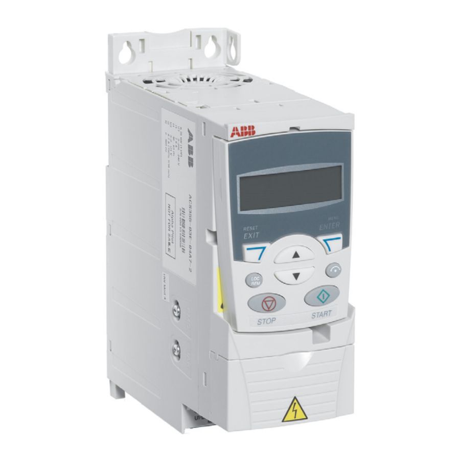
ABB ACS355 Series - DC Drive Quick Installation And Start-up Guide
- User manual (437 pages) ,
- Quick start up manual (139 pages) ,
- Quick installation manual (83 pages)
Advertisement
- 1 Examine the installation area
- 2 Install the drive
- 3 Attach the clamping plates
- 4 Measure the insulation resistance
- 5 Select the cables
- 6 Connect the power cables
- 7 Connect the control cables
- 8 Connection procedure
- 9 Install the fieldbus module (optional)
- 10 Install the control panel (if any)
- 11 Start up the drive
- 12 Related documents
- 13 Fault codes
- 14 Ratings
- 15 Fuses and typical power cable sizes
- 16 Ambient conditions
- 17 Dimensions and weights
- 18 Free space requirements
- 19 Documents / Resources
Examine the installation area
The drive is intended for cabinet installation and has a degree of protection of IP20 / UL open type as standard.
- Make sure that in the installation area:
- There is sufficient space above and below the drive for cooling, and hot air does not recirculate. Refer to Free space requirements.
- The ambient conditions are suitable. Refer to Ambient conditions.
- The mounting surface is non-flammable and can hold the
- Materials near the drive are non-flammable.
- There are no sources of strong magnetic fields, such as high-current singlecore conductors or contactor coils near the drive. A strong magnetic field can cause interference in the operation of the drive.
Install the drive
You can install the drive with screws or to a DIN rail [Top Hat, W x H = 35 × 7.5 mm (1.4 × 0.3 in)].
- Make sure that there is a minimum of 75 mm (3 in) of free space above and below the drive for cooling air.
- When placing drives on top of each other in a panel or cabinet, make sure that the hot air from the drives below do not directly enter the drive above.

Do not install the drive upside down. Make sure that the cooling air exhaust (at the top) is above the cooling air inlet (at the bottom).
To install the drive with screws
- Cut out the mounting template from the package and use it to mark the locations for the mounting holes.

- Make the holes for the mounting screws and install suitable plugs or anchors.

- Start to tighten the screws into the mounting holes.

- Place the drive onto the mounting screws.

- Tighten the mounting screws securely.


To install the drive to a DIN rail
- Place the top of the drive onto the DIN installation rail in an angle as shown in figure.

- Set the drive against the wall.
- To remove the drive, press the release lever on top of the drive.


Attach the clamping plates
- Fasten the clamping plate to the plate at the bottom of the drive with the provided screws.

- Frame sizes R0...R2: Fasten the I/O clamping plate to the clamping plate with the provided screws.


Measure the insulation resistance
Measuring the insulation is typically not required in North America.
Drive: Do not do voltage tolerance or insulation resistance tests on the drive, because this can cause damage to the drive.
Input power cable: Before you connect the input power cable, measure the insulation of the input power cable. Obey the local regulations.
Motor and motor cable:
- Make sure that the motor cable is connected to the motor and disconnected from the drive output terminals U2, V2 and W2.
- Use a voltage of 1000 V DC to measure the insulation resistance between each phase conductor and the protective earth conductor. The insulation resistance of an ABB motor must be more than 100 Mohm (at 25°C/77°F). For the insulation resistance of other motors, refer to the manufacturer's documentation. Moisture in the motor decreases the insulation resistance. If you think that there is moisture in the motor, dry the motor and do the measurement again.


Select the cables
Input power cable: IEC/EN 61800-5-1 requires two protective earth (ground) conductors. Prefer a symmetrical shielded cable (VFD cable).
Motor cable: Use a symmetrical shielded cable (VFD cable) for the best EMC performance and to meet the European EMC requirements.
Control cable: Use a double-shielded twisted-pair cable for analog signals. Use a double- or single-shielded cable for digital, relay and I/O signals. Do not mix 24 V and 115/230 V signals in the same cable.
Connect the power cables
Connection diagram (shielded cables)
")
- 360-degree grounding of the cable shield. Required for the motor cable and brake resistor cable, recommended for the input power cable.
- Use a separate grounding cable if the conductivity of the cable shield is not sufficient (smaller than the conductivity of the phase conductor) for the protective grounding, or there is no symmetrically constructed grounding conductor in the cable.
- In one-phase installations, connect phase to U1/L, neutral to V1/N and leave W1 disconnected.
- Use two grounding conductors if the cross-section of a single grounding conductor is less than 10 mm2 Cu or 16 mm2 AI (IEC/EN 61800-5-1). For example, use the cable shield in addition to the fourth conductor.
- Use a separate grounding cable (line side) if the conductivity of the fourth conductor or shield is not sufficient for the protective grounding.
Connection procedure (shielded cables)
Make sure that the drive is compatible with the earthing system. You can connect all drive types to a symmetrically grounded TN-S system. For other systems, see the drive user's manual.
- Strip the input power cable. Ground the cable shield (if any) under the grounding clamp. Twist the cable shield into a bundle, mark it accordingly and connect it to the grounding terminal. Connect other grounding conductors (PE) to the grounding terminal. Connect the phase conductors to the U1, V1 and W1 terminals.
 - Step 1")
- Strip the motor cable. Ground the cable shield under the grounding clamp. Twist the motor cable shield into a bundle, mark it accordingly and connect it to the grounding terminal. Connect the phase conductors to the U2, V2 and W2 terminals.
 - Step 2")
- If applicable, connect the brake resistor cable to the BRK+ and BRK- terminals. Use a shielded cable and ground the shield under the grounding clamp.
- Mechanically attach the cables on the outside of the drive.
 - Step 3")
 - Step 1")
 - Step 2")
 - Step 3")
| Frame size | Tightening torques | |
| U1, V1, W1, U2, V2, W2, BRK+ and BRK- | PE | |
| R0...R2 | 0.8 N·m (7 lbf·in) | 1.2 N·m (11 lbf·in) |
| R3 | 1.7 N·m (15 lbf·in) | 1.2 N·m (11 lbf·in) |
| R4 | 2.5 N·m (22 lbf·in) | 1.2 N·m (11 lbf·in) |
Connect the control cables
Default I/O connections
The diagram shows the I/O connections when parameter9902 has value 1 (ABB STANDARD).

- AI1 is used as a speed reference if vector mode is selected.
- See parameter group 12 CONSTANT SPEEDS:
| DI3 | DI4 | Operation (par.) |
| 0 | 0 | Set speed through AI1 |
| 1 | 0 | Speed 1 ( 1202 ) |
| 0 | 1 | Speed 2 ( 1203 ) |
| 1 | 1 | Speed 3 ( 1204 ) |
- 0 = ramp times according to parameters 2202 and 2203. 1 = ramp times according to parameters 2205 and 2206.
- 360 degree grounding under a clamp.
Tightening torque: 0.4 N·m / 3.5 lbf·in.
Connection procedure
To prevent inductive coupling, keep the signal wire pairs twisted all the way up to the terminals.
- Remove the terminal cover.

- Strip the outer insulation of the cable and ground the bare shield 360 degrees under the clamp.
- Connect the conductors to the correct control terminals. Torque the terminals to 0.4 N·m (3.5 lbf·in).

- For double-shielded cables, twist also the grounding conductors of each pair in the cable together and connect the bundle to the SCR terminal (terminal 1).
- Mechanically attach the control cables on the outside of the drive.
- If you are going to use an optional Safe Torque Off function, connect STO conductors to the correct terminals. Use a tightening torque of 0.4 N·m (3.5 lbf·in).
- Unless you need to install the optional fieldbus module, slide the terminal cover back into place.


Install the fieldbus module (optional)
Install the control panel (if any)
Start up the drive
Before you start up the drive, make sure that the installation is complete. Make sure that the cover of the drive is in place. Make sure also that the motor does not cause danger when it starts. Disconnect the motor from other machinery, if there is a risk of damage or injury.
There is an extensive installation checklist in the drive user's manual.
Start up without a control panel
- Apply input power and wait for a moment.
- Check that the red LED is not lit and the greed LED is lit but not blinking.
The drive is now ready for use.
Start up with a control panel (manual start-up)
You can use the basic control panel or the assistant control panel. The instructions below are valid for both control panels, but the displays shown are the basic control panel displays, unless the instruction applies to the assistant control panel only.
Before you start, ensure that you have the motor nameplate data at hand.
| POWER-UP | ||
| Apply input power. The basic control panel powers up into the Output mode. |  | |
| The assistant control panel asks if you want to run the Start-up assistant. If you press  , the Start-up assistant is not run, and you can continue with manual start-up in a similar manner as described below for the basic control panel. , the Start-up assistant is not run, and you can continue with manual start-up in a similar manner as described below for the basic control panel. |  | |
| ENTRY OF START-UP DATA (parameter group 99) | ||
| If you have an assistant control panel, select the language. See parameter 9901 for the values of the available language alternatives. |  | |
| Select the motor type ( 9903 ). 1 ( AM ): Asynchronous motor 2 ( PMSM ): Permanent magnet synchronous motor. |  | |
Setting of parameter 9903 is shown below as an example of parameter setting with the basic control panel.
|  | |
| Select the application macro ( 9902 ) according to how the control cables are connected. The default value 1 ( ABB STANDARD ) is suitable in most cases. |  | |
Select the motor control mode ( 9904 ).
|  | |
| Enter the motor data from the motor... nameplate: motor nominal voltage ( 9905 ), nominal motor current ( 9906 ), motor nominal frequency ( 9907 ), motor nominal speed ( 9908 ), motor nominal power ( 9909 ) | ... | |
| Select the motor identification method ( 9910 ). The default value 0 ( OFF/IDMAGN ) using the identification magnetization is suitable for most applications. It is applied here. (Requires also that 9904 is set to 1 ( VECTOR: SPEED ) or 2 ( VECTOR: TORQ )). |  | |
| IDENTIFICATION MAGNETIZATION WITH ID RUN SELECTION 0 ( OFF/IDMAGN ) | ||
Press key  to switch to local control (LOC shown on the left). Press to switch to local control (LOC shown on the left). Press  to start the drive. to start the drive.The motor model is now calculated by magnetizing the motor for 10 to 15 s at zero speed. |  | |
| DIRECTION OF THE MOTOR ROTATION | ||
Check the direction of the motor rotation.
|  | |
| To change the forward and reverse rotation directions (with a parameter): Invert the phases by changing the value of parameter 9914 to the opposite, ie, from 0 ( NO ) to 1 ( YES ), or vice versa. Verify your work by repeating the rotation direction check as described above. |  | |
| SPEED LIMITS AND ACCELERATION/DECELERATION TIMES | ||
| Set the minimum speed ( 2001 ), maximum speed ( 2002 ), acceleration time 1 ( 2202 ), and deceleration time 1 ( 2203 ) |  | |
| SAVING A USER MACRO AND FINAL CHECK | ||
| The start-up is now completed. If you want to save your setting as a user macro, scroll to Parameter 9902 and select value USER S1 SAVE. Check that there are no faults or alarms shown on the display. |  | |
| The drive is now ready for use. | ||
 if the bottom line shows OUTPUT; otherwise press
  repeatedly until you see MENU at the bottom.
 /
/  until you see "PAr".
 under the value. If necessary, change the value with keys
  to stop the motor.
Configure fieldbus communication (optional)
See the drive user's manual.
Related documents

ACS355 user's manual

ACS355 manual list
Fault codes
This is a short list of fault messages.
| Fault | Description |
| 0001 | OVERCURRENT - Output current has exceeded trip level. |
| 0002 | DC OVERVOLT - Excessive intermediate circuit DC voltage. |
| 0003 | DEV OVERTEMP - Drive IGBT temperature is excessive. |
| 0004 | SHORT CIRC - Short-circuit in motor cable(s) or motor. |
| 0006 | DC UNDERVOLT - Intermediate circuit DC voltage is not sufficient. |
| 0009 | MOT OVERTEMP - Motor temperature estimation is too high. |
| 0016 | EARTH FAULT - Drive has detected earth (ground) fault in motor or motor cable. |
| 0022 | SUPPLY PHASE - Intermediate circuit DC voltage is oscillating due to missing input power line phase or blown fuse. |
| 0044 | SAFE TORQUE OFF - STO (Safe torque off) requested via STO terminal and it functions correctly. Parameter 3025 STO OPERATION is set to react with fault. |
Ratings
| ACS355-... x = E/U | Input | Input with choke | Output | Frame size | ||||||
| I 1N | I 1N (480 V) | I 1N (480 V) | I 1N | I 2N | I 2,1/10 | I 2max | PN | |||
| A | A | A | A | A | A | A | kW | hp | ||
| 1-phase U N = 230 V (200...240 V) | ||||||||||
| 01x-02A4-2 | 6.1 | - | 4.5 | - | 2.4 | 3.6 | 4.2 | 0.37 | 0.5 | R0 |
| 01x-04A7-2 | 11 | - | 8.1 | - | 4.7 | 7.1 | 8.2 | 0.75 | 1 | R1 |
| 01x-06A7-2 | 16 | - | 11 | - | 6.7 | 10.1 | 11.7 | 1.1 | 1.5 | R1 |
| 01x-07A5-2 | 17 | - | 12 | - | 7.5 | 11.3 | 13.1 | 1.5 | 2 | R2 |
| 01x-09A8-2 | 21 | - | 15 | - | 9.8 | 14.7 | 17.2 | 2.2 | 3 | R2 |
| 3-phase U N = 230 V (200...240 V) | ||||||||||
| 03x-02A4-2 | 4.3 | - | 2.2 | - | 2.4 | 3.6 | 4.2 | 0.37 | 0.5 | R0 |
| 03x-03A5-2 | 6.1 | - | 3.5 | - | 3.5 | 5.3 | 6.1 | 0.55 | 0.75 | R0 |
| 03x-04A7-2 | 7.6 | - | 4.2 | - | 4.7 | 7.1 | 8.2 | 0.75 | 1 | R1 |
| 03x-06A7-2 | 12 | - | 6.1 | - | 6.7 | 10.1 | 11.7 | 1.1 | 1.5 | R1 |
| 03x-07A5-2 | 12 | - | 6.9 | - | 7.5 | 11.3 | 13.1 | 1.5 | 2 | R1 |
| 03x-09A8-2 | 14 | - | 9.2 | - | 9.8 | 14.7 | 17.2 | 2.2 | 3 | R2 |
| 03x-13A3-2 | 22 | - | 13 | - | 13.3 | 20.0 | 23.3 | 3 | 3 | R2 |
| 03x-17A6-2 | 25 | - | 14 | - | 17.6 | 26.4 | 30.8 | 4 | 5 | R2 |
| 03x-24A4-2 | 41 | - | 21 | - | 24.4 | 36.6 | 42.7 | 5.5 | 7.5 | R3 |
| 03x-31A0-2 | 50 | - | 26 | - | 31 | 46.5 | 54.3 | 7.5 | 10 | R4 |
| 03x-46A2-2 | 69 | - | 41 | - | 46.2 | 69.3 | 80.9 | 11.0 | 15 | R4 |
| 3-phase U N = 400/480 V (380...480 V) | ||||||||||
| 03x-01A2-4 | 2.2 | 1.8 | 1.1 | 0.9 | 1.2 | 1.8 | 2.1 | 0.37 | 0.5 | R0 |
| 03x-01A9-4 | 3.6 | 3.0 | 1.8 | 1.5 | 1.9 | 2.9 | 3.3 | 0.55 | 0.75 | R0 |
| 03x-02A4-4 | 4.1 | 3.4 | 2.3 | 1.9 | 2.4 | 3.6 | 4.2 | 0.75 | 1 | R1 |
| 03x-03A3-4 | 6.0 | 5.0 | 3.1 | 2.6 | 3.3 | 5.0 | 5.8 | 1.1 | 1.5 | R1 |
| 03x-04A1-4 | 6.9 | 5.8 | 3.5 | 2.9 | 4.1 | 6.2 | 7.2 | 1.5 | 2 | R1 |
| 03x-05A6-4 | 9.6 | 8.0 | 4.8 | 4.0 | 5.6 | 8.4 | 9.8 | 2.2 | 3 | R1 |
| 03x-07A3-4 | 12 | 9.7 | 6.1 | 5.1 | 7.3 | 11.0 | 12.8 | 3 | 3 | R1 |
| 03x-08A8-4 | 14 | 11 | 7.7 | 6.4 | 8.8 | 13.2 | 15.4 | 4 | 5 | R1 |
| 03x-12A5-4 | 19 | 16 | 11 | 9.5 | 12.5 | 18.8 | 21.9 | 5.5 | 7.5 | R3 |
| 03x-15A6-4 | 22 | 18 | 12 | 10 | 15.6 | 23.4 | 27.3 | 7.5 | 10 | R3 |
| 03x-23A1-4 | 31 | 26 | 18 | 15 | 23.1 | 34.7 | 40.4 | 11 | 15 | R3 |
| 03x-31A0-4 | 52 | 43 | 25 | 20 | 31 | 46.5 | 54.3 | 15 | 20 | R4 |
| 03x-38A0-4 | 61 | 51 | 32 | 26 | 38 | 57 | 66.5 | 18.5 | 25 | R4 |
| 03x-44A0-4 | 67 | 56 | 38 | 32 | 44 | 66 | 77.0 | 22.0 | 30 | R4 |
I1N - continuous rms input current (for dimensioning cables and fuses)
I1N (480 V) - continuous rms input current (for dimensioning cables and fuses) for drives with 480 V input voltage
I2N - continuous rms current. 50% overload is allowed for one minute every ten minutes.
I2,1/10 - maximum (50% overload) current allowed for one minute every ten minutes
I2max - maximum output current. Available for two seconds at start, otherwise as long as allowed by the drive temperature.
PN - typical motor power. The kilowatt ratings apply to most IEC 4-pole motors. The horsepower ratings apply to most NEMA 4-pole motors.
Fuses and typical power cable sizes
The table list the fuses for protection against short-circuits in the input power cable or drive. The table also shows typical power cable sizes.
| ACS355-... x = E/U | Fuses | Size of copper conductor | ||||||||
| gG | UL Class T or CC (600 V) | Supply (U1, V1, W1) | Motor (U2, V2, W2) | PE | Brake (BRK+, BRK-) | |||||
| A | A | mm 2 | AWG mm | 2 | AWG | mm 2 | AWG | mm 2 | AWG | |
| 1-phase UN = 230 V (200...240 V) | ||||||||||
| 01x-02A4-2 | 10 | 10 | 2.5 | 14 | 0.75 | 18 | 2.5 | 14 | 2.5 | 14 |
| 01x-04A7-2 | 16 | 20 | 2.5 | 14 | 0.75 | 18 | 2.5 | 14 | 2.5 | 14 |
| 01x-06A7-2 | 16/201) | 25 | 2.5 | 10 | 1.5 | 14 | 2.5 | 10 | 2.5 | 12 |
| 01x-07A5-2 | 20/25 1) | 30 | 2.5 | 10 | 1.5 | 14 | 2.5 | 10 | 2.5 | 12 |
| 01x-09A8-2 | 25/351) | 35 | 6 | 10 | 2.5 | 12 | 6 | 10 | 6 | 12 |
| 3-phase UN = 230 V (200...240 V) | ||||||||||
| 03x-02A4-2 | 10 | 10 | 2.5 | 14 | 0.75 | 18 | 2.5 | 14 | 2.5 | 14 |
| 03x-03A5-2 | 10 | 10 | 2.5 | 14 | 0.75 | 18 | 2.5 | 14 | 2.5 | 14 |
| 03x-04A7-2 | 10 | 15 | 2.5 | 14 | 0.75 | 18 | 2.5 | 14 | 2.5 | 14 |
| 03x-06A7-2 | 16 | 15 | 2.5 | 12 | 1.5 | 14 | 2.5 | 12 | 2.5 | 12 |
| 03x-07A5-2 | 16 | 15 | 2.5 | 12 | 1.5 | 14 | 2.5 | 12 | 2.5 | 12 |
| 03x-09A8-2 | 16 | 20 | 2.5 | 12 | 2.5 | 12 | 2.5 | 12 | 2.5 | 12 |
| 03x-13A3-2 | 25 | 30 | 6 | 10 | 6 | 10 | 6 | 10 | 2.5 | 12 |
| 03x-17A6-2 | 25 | 35 | 6 | 10 | 6 | 10 | 6 | 10 | 2.5 | 12 |
| 03x-24A4-2 | 63 | 60 | 10 | 8 | 10 | 8 | 10 | 8 | 6 | 10 |
| 03x-31A0-2 | 80 | 80 | 16 | 6 | 16 | 6 | 16 | 6 | 10 | 8 |
| 03x-46A2-2 | 100 100 | 25 | 2 | 25 | 2 | 16 | 4 | 10 | 8 | |
| 3-phase UN = 400/480 V (380...480 V) | ||||||||||
| 03x-01A2-4 | 10 | 10 | 2.5 | 14 | 0.75 | 18 | 2.5 | 14 | 2.5 | 14 |
| 03x-01A9-4 | 10 | 10 | 2.5 | 14 | 0.75 | 18 | 2.5 | 14 | 2.5 | 14 |
| 03x-02A4-4 | 10 | 10 | 2.5 | 14 | 0.75 | 18 | 2.5 | 14 | 2.5 | 14 |
| 03x-03A3-4 | 10 | 10 | 2.5 | 12 | 0.75 | 18 | 2.5 | 12 | 2.5 | 12 |
| 03x-04A1-4 | 16 | 15 | 2.5 | 12 | 0.75 | 18 | 2.5 | 12 | 2.5 | 12 |
| 03x-05A6-4 | 16 | 15 | 2.5 | 12 | 1.5 | 14 | 2.5 | 12 | 2.5 | 12 |
| 03x-07A3-4 | 16 | 20 | 2.5 | 12 | 1.5 | 14 | 2.5 | 12 | 2.5 | 12 |
| 03x-08A8-4 | 20 | 25 | 2.5 | 12 | 2.5 | 12 | 2.5 | 12 | 2.5 | 12 |
| 03x-12A5-4 | 25 | 30 | 6 | 10 | 6 | 10 | 6 | 10 | 2.5 | 12 |
| 03x-15A6-4 | 35 | 35 | 6 | 8 | 6 | 8 | 6 | 8 | 2.5 | 12 |
| 03x-23A1-4 | 50 | 50 | 10 | 8 | 10 | 8 | 10 | 8 | 6 | 10 |
| 03x-31A0-4 | 80 | 80 | 16 | 6 | 16 | 6 | 16 | 6 | 10 | 8 |
| 03x-38A0-4 | 100 | 100 | 16 | 4 | 16 | 4 | 16 | 4 | 10 | 8 |
| 03x-44A0-4 | 100 | 100 | 25 | 4 | 25 | 4 | 16 | 4 | 10 | 8 |
1) If 50% overload capacity is needed, use the larger fuse alternative.
Ambient conditions
| Requirement | During operation (installed for stationary use) |
| Installation altitude | 0...2000 m (0...6562 ft) above sea level (with output derating above 1000 m [3281 ft]) |
| Surrounding air temperature | -10...+50°C (14...122°F). If the temperature is more than 40°C (104°F), output derating is necessary. No frost permitted. |
| Relative humidity | 0...95% without condensation |
| Contamination levels (IEC 60721-3-3: 2002) | No conductive dust permitted |
| Shock (IEC 60068-2-27, ISTA 1A) | Not permitted |
| Free fall | Not permitted |
Dimensions and weights
| IP20 (cabinet) / UL open | ||||||||||||
| Frame size | H1 | H2 | H3 | W | D | Weight | ||||||
| mm | in | mm | in | mm | in | mm | in | mm | in | kg | lb | |
| R0 | 169 | 6.65 | 202 | 7.95 | 239 | 9.41 | 70 | 2.76 | 161 | 6.34 | 1.2 | 2.6 |
| R1 | 169 | 6.65 | 202 | 7.95 | 239 | 9.41 | 70 | 2.76 | 161 | 6.34 | 1.4 | 3.0 |
| R2 | 169 | 6.65 | 202 | 7.95 | 239 | 9.41 | 105 | 4.13 | 165 | 6.50 | 1.8 | 3.9 |
| R3 | 169 | 6.65 | 202 | 7.95 | 236 | 9.29 | 169 | 6.65 | 169 | 6.65 | 3.1 | 6.9 |
| R4 | 181 | 7.13 | 202 | 7.95 | 244 | 9.61 | 260 | 10.24 | 169 | 6.65 | 5.2 | 11.5 |
| IP20 / NEMA 1 | ||||||||||||
| Frame size | H4 | H5 | W | D | - | Weight | ||||||
| mm | in | mm | in | mm | in | mm | in | - | - | kg | lb | |
| R0 | 257 | 10.12 | 280 | 11.02 | 70 | 2.76 | 169 | 6.65 | - | - | 1.6 | 3.5 |
| R1 | 257 | 10.12 | 280 | 11.02 | 70 | 2.76 | 169 | 6.65 | - | - | 1.8 | 3.9 |
| R2 | 257 | 10.12 | 282 | 11.10 | 105 | 4.13 | 169 | 6.65 | - | - | 2.2 | 4.8 |
| R3 | 260 | 10.24 | 299 | 11.77 | 169 | 6.65 | 177 | 6.97 | - | - | 3.7 | 8.2 |
| R4 | 270 | 10.63 | 320 | 12.60 | 260 | 10.24 | 177 | 6.97 | - | - | 5.8 | 12.9 |
IP20 (cabinet) / UL open
H1 height without fastenings or clamping plate
H2 height with fastening and without clamping plate
H3 height with fastenings and clamping plate
W width
D depth
IP20 / NEMA 1 (drive with optional MUL-xx kit installed)
H4 height with fastenings and connection box
H5 height with fastenings, connection box and hood
Free space requirements
| Above | Below | Sides | |||
| mm | in | mm | in | mm | in |
| 75 | 3 | 75 | 3 | 0 | 0 |

Documents / ResourcesDownload manual
Here you can download full pdf version of manual, it may contain additional safety instructions, warranty information, FCC rules, etc.
Download ABB ACS355 Series - DC Drive Quick Installation And Start-up Guide
Advertisement
Thank you! Your question has been received!


Need Assistance?
Do you have a question about the ACS355 Series that isn't answered in the manual? Leave your question here.