ABB ACS320 Supplemental Manual
Variable frequency drives in renewaire ventilators
Hide thumbs
Also See for ACS320:
- User manual (442 pages) ,
- Installation instructions (4 pages) ,
- Installation instructions (4 pages)
Advertisement
Quick Links
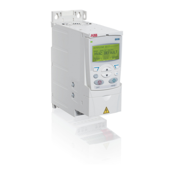
MODEL SHOWN: ACS 320
VFD KEYPADS IN E-BOX
VFD KEYPADS IN E-BOX
SUPPLEMENTAL
MANUAL
FACTORY-INSTALLED
ABB VARIABLE FREQUENCY
DRIVES (VFD)
IN RENEWAIRE
(ERV) VENTILATORS
TABLE OF CONTENTS
Product info ............................ 2
Installation ........................... 3-9
Operation ......................... 10-16
RENEWAIRE.COM
Advertisement

Related Manuals for ABB ACS320


Summary of Contents for ABB ACS320
- Page 1 SUPPLEMENTAL MANUAL FACTORY-INSTALLED ABB VARIABLE FREQUENCY DRIVES (VFD) IN RENEWAIRE (ERV) VENTILATORS MODEL SHOWN: ACS 320 TABLE OF CONTENTS Product info ......2 Installation ......3-9 Operation ......10-16 VFD KEYPADS IN E-BOX VFD KEYPADS IN E-BOX RENEWAIRE.COM...
- Page 2 ABB VARIABLE FREQUENCY DRIVES PRODUCT INFO ABOUT ABB VFDS ABB ACS320 VFDs are generally supplied in indoor ERVs and ABB ACS355+N831 VFDs in roof top ERVs. ® Both models have built in BACnet building communication protocol and the ACS355+N831 also has low ambient fi...
- Page 3 90 degrees plug locations. Bring wires out from the top or as possible. See the ABB VFD manual for more bottom of the VFD mounting bracket and not detailed wire routing instructions.
- Page 4 For questions about applications not covered in this manual, and for questions specifi c to the ABB Drives, contact ABB Technical Support at 800-HELP-365 (800-435-7365). A listing of ABB support and service contacts can be found on the Internet at www.abb.com/drives and selecting Sales, Support and Service Network.
- Page 5 ABB VARIABLE FREQUENCY DRIVES INSTALLATION “ON” SIGNAL CONNECTIONS WIRING OPTIONS If the ERV is equipped with Damper(s) and/or with just one VFD, the ON Signal control wires are connected to the low-voltage terminal strip in the ERV E-box. See Fig. 1.
- Page 6 ABB VARIABLE FREQUENCY DRIVES INSTALLATION WIRING SCHEMATICS FACTORY CONTROL WIRING: ON SIGNALS CONNECTED TO EACH VFD. NOTE: ERV may optionally have See Fig. 1 for Relay or Damper Actuator AGND only one VFD. Connection alternatives. AGND AGND AGND DO NOT CONNECT POWER TO...
- Page 7 ABB VARIABLE FREQUENCY DRIVES INSTALLATION ANALOG INPUTS TO PROVIDE THE SPEED SIGNAL WIRING SCHEMATICS Analog inputs are connected as shown below. It may be necessary to scale the response of the VFD to the analog SPEED signal. See example of VFD Parameter Scaling in Figure 9 (F9).
- Page 8 The VFD can be programmed with 3 pre-set speeds. Contact switches can then be used to direct the VFD to operate at one of those speeds. See ABB manuals for additional options. Leader-follower wiring can also be used to make a second VFD operate at the same speed as the fi rst VFD.
- Page 9 TO ACCESS POWER AND CONTROL WIRES UNDERNEATH FMBA-01 MODULE The ACS355+N831 VFD will typically be provided with ABB FMBA-01 Modbus Adapter Module installed on the VFD. This module will need to be removed if access is required to the power and control wire terminals below it.
- Page 10 Change the VFD parameters as required for the specifi c controls system (see “Control Connections” - 9906 MOTOR NOM CURR and “VFD Parameters”, below, for examples; see also the ABB Manuals.) Change to match the motor Press the AUTO switch on the keypad.
- Page 11 ABB VARIABLE FREQUENCY DRIVES OPERATION VFD PARAMETER OVERVIEW SETTINGS “VFD Parameters” are instructions that the Variable Frequency Drives follow. They can be adjusted by using the keypads on the VFDs. In some control confi gurations, they will need to be changed from the settings as shipped in the unit to interface with your control system.
- Page 12 ABB VARIABLE FREQUENCY DRIVES OPERATION SETTINGS SUMMARY TABLE OF COMMONLY USED PARAMETERS NOTE: Parameters not listed in this Table are shipped at ABB’s default settings for the HVAC Application Macro. ABB HVAC Default ACS320/ Settings as Shipped By Name/Selection FUNCTION...
- Page 13 Sets bottom line of keypad display to show value of analog signal input.*** * This parameter is not visible in the “short view”. To be able to view all signals and parameters, set parameter 1611 PARAMETER VIEW to 3 (LONG VIEW) on ACS320 VFDs.
- Page 14 ABB VARIABLE FREQUENCY DRIVES OPERATION SETTINGS WARNING DANGER OF MOTOR OVERLOAD LEADING TO SMOKE AND FIRE! Do not change PARAMETER 2003 MAX CURRENT from RenewAire default setting, which should be set to no more than 125% of the motor nameplate FLA for motors with 1.15 Service Factor (SF) or higher or 115% of the motor FLA for motors with less than 1.15 SF and otherwise unprotected.
- Page 15 ABB VARIABLE FREQUENCY DRIVES OPERATION ADDITIONAL JOB INFORMATION NEEDED: SETTINGS 1. MEASUREMENT RANGE: the range of the values that can be measured by the Controller (e.g. a controller set to measure CO2 from 0ppm to 1100ppm). 2. ANALOG SIGNAL TYPE: vdc or mA.
- Page 16 ABB VARIABLE FREQUENCY DRIVES ABB VDF OPERATION SETTINGS F9 EXAMPLE CALCULATIONS AND SETTING THE PARAMETERS 1. Set the VFD parameters for the minimum and maximum SPEEDS of the VFD: • Set Parameter 1104 REF1 MIN to “20Hz”. The motors will never run below this speed.