ABB ACS355 Series Supplement Manual
Drives with ip66/67 / ul type 4x enclosure (0.37...7.5 kw, 0.5...10 hp)
Hide thumbs
Also See for ACS355 Series:
- Installation manual ,
- User manual (437 pages) ,
- Quick start up manual (139 pages)
Table of Contents
Advertisement
Quick Links
Advertisement
Table of Contents

Related Manuals for ABB ACS355 Series


Summary of Contents for ABB ACS355 Series
- Page 1 ABB general machinery drives Supplement ACS355 drives with IP66/67 / UL Type 4X enclosure (0.37…7.5 kW, 0.5…10 HP) 3AUA0000066066 REV B Effective: 2010-01-01 © 2010 ABB Oy. All rights reserved. Buy: www.ValinOnline.com | Phone 844-385-3099 | Email: CustomerService@valin.com...
-
Page 2: Table Of Contents
Providing feedback on ABB Drives manuals ........ - Page 3 Electrical installation What this chapter contains ............39 Checking the insulation of the assembly .
- Page 4 Compliance with EN 61800-3 (2004) ..........55 Applicable standards .
- Page 5 ACS355 drives with IP66/67 / UL Type 4X enclosure 0.37…7.5 kW 0.5…10 HP Supplement 3AUA0000066066 REV B EFFECTIVE: 2010-01-01 © 2010 ABB Oy. All Rights Reserved. Buy: www.ValinOnline.com | Phone 844-385-3099 | Email: CustomerService@valin.com...
-
Page 6: Safety
Safety What this chapter contains The chapter contains the safety instructions which you must follow when installing, operating and servicing the drive. If ignored, physical injury or death may follow, or damage may occur to the drive, motor or driven equipment. Read the safety instructions before you work on the drive. -
Page 7: Installation And Maintenance Work
ACS355 user’s manual. • The drive is not field repairable. Never attempt to repair a malfunctioning drive; contact your local ABB representative or Authorized Service Center for replacement. • Make sure that dust from drilling does not enter the drive during the installation. -
Page 8: Operation And Start-Up
Operation and start-up These warnings are intended for all who plan the operation, start up or operate the drive. WARNING! Ignoring the following instructions can cause physical injury or death, or damage to the equipment. • Before adjusting the drive and putting it into service, make sure that the motor and all driven equipment are suitable for operation throughout the speed range provided by the drive. -
Page 9: About The Manual
About the manual What this chapter contains The chapter describes the intended audience and compatibility of this manual. It also contains a flowchart of steps for checking the delivery and installing and commissioning the drive. The flowchart refers to chapters/sections in this manual and the ACS355 user’s manual. -
Page 10: Categorization According To The Frame Size
Address any inquiries about the product to your local ABB representative, quoting the type code and serial number of the unit in question. A listing of ABB sales, support and service contacts can be found by navigating to ABB website and selecting Sales, Support and Service network. - Page 11 Installation and commissioning flowchart Task Identify the frame size of your drive: R1 or R3. Technical data: Ratings on page Plan the installation: select the cables, etc. Planning electrical installation in the ACS355 user’s manual and Power cable sizes and fuses Check the ambient conditions, ratings and required on page 52.
-
Page 12: Hardware Description
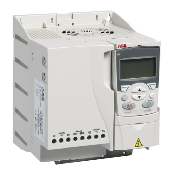
Hardware description What this chapter contains The chapter describes the construction and type code information in short. Overview The ACS355 with IP66/67 / UL Type 4X enclosure is a wall mountable drive for controlling AC motors. The construction of frame sizes R1 and R3 varies to some extent. - Page 13 Covers on (R3) Covers off (R3) 1 Cooling element 8 Panel connection 2 Mounting holes 9 Safe torque off connection 3 Control Panel 10 Option connection 4 Front cover 11 FlashDrop connection 5 EMC filter grounding screw (EMC). 12 Power OK and Fault LEDs 6 Varistor grounding screw (VAR) 13 Fieldbus adapter (serial communication module) connection...
-
Page 14: Overview: Connections
Overview: Connections See the ACS355 user’s manual. Type code The type code contains information on the specifications and configuration of the drive. You find the type code on the type designation label attached to the drive. The first digits from the left express the basic configuration, for example ACS355-03E- 08A8-4+B063. -
Page 15: Mechanical Installation
Mechanical installation What this chapter contains The chapter describes the mechanical installation procedure of the drive. Safety WARNING! Do not install anything inside the drive that is not explicitly instructed in this manual or the ACS355 user’s manual. WARNING! Do not install the drive outdoors. The drive is intended for indoor use only. -
Page 16: Unpacking The Drive
Unpacking the drive The package contains the following items: • (1) ACS355 with IP66/67 UL Type 4X enclosure and Assistant Control Panel (frame size R3 shown in the figure) • (2) user’s manual and (3) IP66/67 UL Type 4X supplement •... -
Page 17: Delivery Check
A, B, C, … for product revision number 0…600 Hz XXXX: Integer starting every week from 0001 5 ABB MRP code of the drive Type designation label 6 RoHS mark, CE marking, UL marking, and TÜV NORD, C-Tick and NSF marks (the label of your drive... -
Page 18: Mounting The Drive And Hygienic Installation
Mounting the drive and hygienic installation Attach the drive to the wall using back mounting. Note: To fulfill the requirements for hygienic installation, leave enough free space around the drive. See Free space around the drive for more information. Note: Make sure that dust from drilling does not enter the drive during the installation. -
Page 19: Installing The Cable Glands (Optional, +H376)
Installing the cable glands (optional, +H376) Note: The lead-throughs are only meant for sealing the enclosure. Do not use them for grounding. 1. Remove the sticker labeled REMOVE BEFORE USE. 2. Tighten the cable glands that you want to use with their back nuts. The tightening torque depends on the cable gland size. -
Page 20: Installing Conduit Fittings
Installing conduit fittings Install conduit fittings according to manufacturer recommendations for hole sizes 1/2" and 3/4". The 12.5 mm diameter hole is for the optional pressure compensation valve (+C169). Do not use it for any other purpose. Cable gland kit part list R1 Cable Gland Kit, R3 Cable Gland Kit, 3AUA0000045483... -
Page 21: Electrical Installation
Electrical installation What this chapter contains The chapter describes the electrical installation procedure of the drive. WARNING! The work described in this chapter may only be carried out by a qualified electrician. Follow the instructions in chapter Safety on page 21. Ignoring the safety instructions can cause injury or death. -
Page 22: Connecting The Power Cables
Connecting the power cables Connection diagram INPUT Drive (L) (N) OUTPUT V1 W1 V2 W2 BRK- BRK+ For alternatives, see section Supply Optional brake disconnecting device resistor in the ACS355 user’s manual. Motor (L) (N) Ground the other end of the PE conductor at the distribution board. Use a separate grounding cable if the conductivity of the cable shield is insufficient (smaller than the conductivity of the phase conductor) and there is no symmetrically constructed grounding conductor in the cable (see section Selecting the power cables in the ACS355 user’s manual). -
Page 23: Procedure
Procedure 1. On IT (ungrounded) systems and corner grounded TN systems, disconnect the internal EMC filter by removing the EMC screw. For 3-phase U-type drives (with type code ACS355-03U-), the EMC screw is already removed at the factory and replaced by a plastic one. WARNING! If a drive whose EMC filter is not disconnected is installed on an IT system [an ungrounded power system or a high resistance-grounded (over 30 ohms) power system], the system will be connected to earth potential through the... -
Page 24: Connecting The Control Cables
Connecting the control cables See the ACS355 user’s manual. Safe torque off (STO) See the ACS355 user’s manual. Electrical installation Buy: www.ValinOnline.com | Phone 844-385-3099 | Email: CustomerService@valin.com... -
Page 25: Installation Checklist
Installation checklist Checklist Check the mechanical and electrical installation of the drive before start-up. Go through the checklist below together with another person. Read chapter Safety the first pages of this manual before you work on the drive. Check MECHANICAL INSTALLATION The ambient operating conditions are allowed. - Page 26 Check Cable glands are tightened and the cover is in place. The gaskets are in place. Installation checklist Buy: www.ValinOnline.com | Phone 844-385-3099 | Email: CustomerService@valin.com...
-
Page 27: Maintenance And Hardware Diagnostics
Ignoring the safety instructions can cause injury or death. Maintenance intervals If installed in an appropriate environment, the drive requires very little maintenance. The table lists the routine maintenance intervals recommended by ABB. Maintenance Interval Instruction... -
Page 28: Cleaning The Drive
If the drive is operated in a critical part of a process, fan replacement is recommended before it has been in use for 25 000 hours or three years. Replacement fans are available from ABB. Do not use other than ABB specified spare parts. -
Page 29: Internal Fan Replacement
Internal fan replacement 1. Stop the drive and disconnect it from the AC power source. 2. Remove the front cover. 3. Open the screw(s) holding the fan in place (1 screw in R1, 2 screws in R3) 4. Free the fan cable from the clip. 5. - Page 30 Maintenance and hardware diagnostics Buy: www.ValinOnline.com | Phone 844-385-3099 | Email: CustomerService@valin.com...
-
Page 31: Technical Data
Technical data What this chapter contains The chapter contains the technical specifications of the drive, e.g. the ratings, sizes and technical requirements as well as provisions for fulfilling the requirements for CE and other marks. Technical data Buy: www.ValinOnline.com | Phone 844-385-3099 | Email: CustomerService@valin.com... -
Page 32: Ratings
Ratings Current and power The current and power ratings are given below. The symbols are described below the table. Type Input Output Frame size ACS355… (+B063) 2,1min/10min 2max x = E/U 3-phase U = 200…240 V (200, 208, 220, 230, 240 V) 03x-02A4-2 0.37 03x-03A5-2... -
Page 33: Sizing
Sizing The current ratings are the same regardless of the supply voltage within one voltage range. To achieve the rated motor power given in the table, the rated current of the drive must be higher than or equal to the rated motor current. Note 1: The maximum allowed motor shaft power is limited to 1.5 ·... -
Page 34: Power Cable Sizes And Fuses
Power cable sizes and fuses Cable dimensioning for rated currents (I ) is shown in the table below together with the corresponding fuse types for short-circuit protection of the input power cable. The rated fuse currents given in the table are the maximum for the mentioned fuse types. -
Page 35: I/O Cables
I/O cables Use I/O cables with a temperature rating of at least 70°C (158°F) maximum permissable temperature of the conductor in continuous use. Power cables: terminal sizes, maximum cable diameters and tightening torques See the ACS355 user’s manual. Dimensions, weights and noise Frame Dimensions and weights Noise... -
Page 36: Degrees Of Protection
Degrees of protection IP66/67 UL Type 4X, indoor use only. IP69K with compatible cable glands Ambient conditions Environmental limits for the drive are given below. The drive is to be used in a heated indoor controlled environment. Operation Storage Transportation installed for stationary use in the protective package in the protective package... -
Page 37: Ce Marking
EU. They must be removed and handled according to local regulations. For further information on environmental aspects and more detailed recycling instructions, please contact your local ABB distributor. Applicable standards The drive complies with the following standards: •... -
Page 38: Nsf Mark
NSF mark The presence on the NSF Mark on food service equipment means that the equipment has been evaluated, tested, and certified by NSF International as meeting international commercial food equipment standards. To earn the right to use the NSF Mark, a manufacturer must pass not only stringent evaluation and testing of its product, but also rigorous, unannounced inspection of its production facilities which are contacted on a routine basis. -
Page 39: Iec/En 61800-3 (2004) Definitions
First environment (drives of category C2) 1. The optional EMC filter is selected according to the ABB documentation and installed as specified in the EMC filter manual. 2. The motor and control cables are selected as specified in this manual. -
Page 40: Product Protection In The Usa
Product protection in the USA This product is protected by one or more of the following US patents: 4,920,306 5,301,085 5,463,302 5,521,483 5,532,568 5,589,754 5,612,604 5,654,624 5,799,805 5,940,286 5,942,874 5,952,613 6,094,364 6,147,887 6,175,256 6,184,740 6,195,274 6,229,356 6,252,436 6,265,724 6,305,464 6,313,599 6,316,896 6,335,607 6,370,049... - Page 41 Dimensions Dimensional drawings of the ACS355 with IP66/67 UL Type 4X enclosure are shown below. The dimensions are given in millimeters and [inches]. Dimensions Buy: www.ValinOnline.com | Phone 844-385-3099 | Email: CustomerService@valin.com...
-
Page 42: Frame Size R1, Ip66/67 Ul Type 4X
Frame size R1, IP66/67 UL Type 4X Dimensions Buy: www.ValinOnline.com | Phone 844-385-3099 | Email: CustomerService@valin.com... -
Page 43: Frame Size R3, Ip66/67 Ul Type 4X
Frame size R3, IP66/67 UL Type 4X Dimensions Buy: www.ValinOnline.com | Phone 844-385-3099 | Email: CustomerService@valin.com... -
Page 44: R1 Gland Plate (Eu)
R1 gland plate (EU) Dimensions Buy: www.ValinOnline.com | Phone 844-385-3099 | Email: CustomerService@valin.com... -
Page 45: R1 Conduit Fitting Plate (Us)
R1 conduit fitting plate (US) Note: The 12.5mm diameter hole is for the optional pressure compensation valve (+C169). Do not use it for any other purpose. Dimensions Buy: www.ValinOnline.com | Phone 844-385-3099 | Email: CustomerService@valin.com... -
Page 46: R3 Gland Plate (Eu)
R3 gland plate (EU) Dimensions Buy: www.ValinOnline.com | Phone 844-385-3099 | Email: CustomerService@valin.com... -
Page 47: R3 Conduit Fitting Plate (Us)
R3 conduit fitting plate (US) Note: The 12.5mm diameter hole is for the optional pressure compensation valve (+C169). Do not use it for any other purpose. Dimensions Buy: www.ValinOnline.com | Phone 844-385-3099 | Email: CustomerService@valin.com...
Need help?
Do you have a question about the ACS355 Series and is the answer not in the manual?
Questions and answers