ABB ACS310 User Manual
Hide thumbs
Also See for ACS310:
- User manual (376 pages) ,
- Quick start manual (48 pages) ,
- User's manual and safety manual (40 pages)

Related Manuals for ABB ACS310


Summary of Contents for ABB ACS310
- Page 1 Short User’s Manual ACS310 Table of contents Safety Mechanical installation Electrical installation Start-up and control with I/O...
-
Page 2: List Of Related Manuals
Document Library, enter the code in the search field and click OK. Applicability The manual is applicable to the ACS310 drive firmware version 4.00E or later. See parameter 3301 FIRMWARE in chapter Actual signals and parameters in ACS310 User’s Manual (3AUA0000044201 [English]). -
Page 3: Table Of Contents
Table of contents 3 Table of contents List of related manuals ............2 Purpose of the manual . - Page 4 Providing feedback on ABB Drives manuals ........
-
Page 5: Safety
Safety 5 1. Safety Safety in installation and maintenance These warnings are intended for all who work on the drive, motor cable or motor. Electrical safety WARNING! Ignoring the following instructions can cause physical injury or death, or damage to the equipment. Only qualified electricians are allowed to install and maintain the drive! •... -
Page 6: Safe Start-Up And Operation
• The drive is not field repairable. Never attempt to repair a malfunctioning drive; contact your local ABB representative or Authorized Service Center for replacement. • Make sure that dust from drilling does not enter the drive during the installation. -
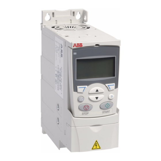
Page 7: Hardware Description
Hardware description 7 2. Hardware description Power connections and control interfaces Control panel (RJ-45) Modbus RTU (RS-232) Screen AO 7 Analog input 1 Analog output 0…10 V 0…20 mA GND 8 Reference voltage +10V +10 V DC, max. 10 mA Analog input 2 +24 V PROGRAMMABLE RELAY... -
Page 8: Type Designation Key
R707 = ACS310 User’s Manual in French (3AUA0000048400 [FR]) R708 = ACS310 User’s Manual in Spanish (3AUA0000048401 [ES]) 1) The ACS310 is compatible with ACS-CP-C Basic Control Panel Rev M or later. 2) The ACS310 is compatible with ACS-CP-A Assistant Control Panel Rev E or later. -
Page 9: Mechanical Installation
1. Mark the locations for the holes using for example the mounting template cut out from the package. The locations of the holes are also shown in the drawings in chapter Dimensions in ACS310 User’s Manual (3AUA0000044201 [English]). The number and location of the holes used depend on how the drive is installed: a) back mounting (frame sizes R0…R4): four holes... - Page 10 10 Mechanical installation 3. Position the drive onto the screws on the wall. 4. Tighten the screws in the wall securely. On DIN rail 1. Click the drive to the rail. To detach the drive, press the release lever on top of the drive (1b).
- Page 11 Mechanical installation 11 Fasten clamping plates 1. Fasten the clamping plate to the plate at the bottom of the drive with the provided screws. 2. Fasten the I/O clamping plate to the clamping plate (frame sizes R0…R2) with the provided screws.
- Page 12 12 Mechanical installation...
-
Page 13: Electrical Installation
1. If you have an IT (ungrounded) or corner grounded TN system, disconnect the internal EMC filter by removing the EMC screw. For 3-phase U-type drives (with type designation ACS310-03U-), the EMC screw is already removed at the factory and replaced by a plastic one. -
Page 14: Connecting The Power Cables
See chapter Planning the electrical installation, section Selecting the power cables in ACS310 User’s Manual (3AUA0000044201 [English]). Note: Do not use an asymmetrically constructed motor cable. - Page 15 Electrical installation 15 Connection procedure 1. Fasten the grounding conductor (PE) of the input power cable under the grounding clamp. Connect the phase conductors to the U1, V1 and W1 terminals. Use a tightening torque of 0.8 N·m (7 lbf·in) for frame sizes R0…R2, 1.7 N·m (15 lbf·in) for R3, and 2.5 N·m (22 lbf·in) for R4.
-
Page 16: Connecting The Control Cables
Parameter values are the default values given in chapter Actual signals and parameters in ACS310 User’s Manual (3AUA0000044201 [English]). The default I/O connections for the ABB standard macro are given in the figure below. Signal cable shield (screen) Output frequency reference: 0…10 V 1…10 kohm... - Page 17 Electrical installation 17 Connection procedure 1. Remove the terminal cover by simultaneously pushing the recess and sliding the cover off the frame. 2. Digital signals: Strip the outer insulation of the digital signal cable 360 degrees and ground the bare shield under the clamp. 3.
-
Page 18: Installation Checklist
Check MECHANICAL INSTALLATION The ambient operating conditions are allowed. (See Technical data: Losses, cooling data and noise and Ambient conditions in ACS310 User’s Manual (3AUA0000044201 [English]).) The drive is fixed properly on an even vertical non-flammable wall. (See Mechanical... -
Page 19: Start-Up And Control With I/O 19
1611 PARAMETER VIEW to 3 (LONG VIEW). • Check the installation. See the checklist in chapter Installation checklist in ACS310 User’s Manual (3AUA0000044201 [English]). How you start up the drive depends on the control panel you have. • If you have a Basic Control Panel, follow the instructions given in section to perform a manual start-up on page 20. - Page 20 SAVE For instructions on how to set parameters with the Assistant Control Panel, see chapter Control panels, section Assistant Control Panel in ACS310 User’s Manual (3AUA0000044201 [English]). Enter the motor data from the motor nameplate: Note: Set the motor data to exactly the same value as on the motor nameplate.
- Page 21 Basic Control Panel. You find more detailed instructions in chapter Control panels, section Basic Control Panel in ACS310 User’s Manual (3AUA0000044201 [English]). 1. To go to the Main menu, press if the bottom line shows OUTPUT;...
- Page 22 22 Start-up and control with I/O DIRECTION OF THE MOTOR ROTATION Check the direction of the motor rotation. • If the drive is in remote control (REM shown on the left), switch to local control by pressing • To go to the Main menu, press if the bottom line shows OUTPUT;...
- Page 23 Start-up and control with I/O 23 How to perform a guided start-up To be able to perform the guided start-up, you need the Assistant Control Panel. Before you start, ensure that you have the motor nameplate data on hand. POWER-UP Apply input power.
- Page 24 24 Start-up and control with I/O Select the application macro according to which the PAR EDIT control cables are connected. 9902 APPLIC MACRO ABB STANDARD EXIT 00:00 SAVE Continue with the application set-up. After CHOICE Do you want to completing a set-up task, the Start-up Assistant continue with suggests the next one.
- Page 25 Start-up and control with I/O 25 FINAL CHECK After the whole set-up is completed, check that there are no faults or alarms shown on the display and the panel LED is green and does not blink. The drive is now ready for use.
-
Page 26: How To Control The Drive Through The I/O Interface
Default I/O connection diagram on page according to the connection diagram given for the ABB Standard macro. Ensure that the drive is in remote control. Press key In remote control, the panel display shows text REM. to switch between remote and local control. -
Page 27: Actual Values And Parameters In The Short View
To be able to view all actual signals and parameters, set parameter 1611 PARAMETER VIEW to 3 (LONG VIEW). For the description of all actual signals and parameters, refer to chapter Actual signals and parameters in ACS310 User’s Manual (3AUA0000044201 [English]). Terms and abbreviations... -
Page 28: Default Values With Different Macros
For other parameters, the default values are the same for all macros. See the parameter list starting on page in this manual and chapter Actual signals and parameters in ACS310 User’s Manual (3AUA0000044201 [English]). Index Name/... -
Page 29: Actual Signals In The Short Parameter View
04 FAULT HISTORY Fault history (read-only) 0401 LAST FAULT Code of the latest fault. See chapter Fault tracing in ACS310 1 = 1 User’s Manual (3AUA0000044201 [English]) for the codes. 0 = Fault history is clear (on panel display = NO RECORD). - Page 30 (4 mA / 20 mA) · 100% = 20% 14 RELAY OUTPUTS Status information indicated through relay output, and relay operating relays. For more information, see chapter Actual signals and parameters in ACS310 User’s Manual (3AUA0000044201 [English]). 1401 RELAY Selects a drive status indicated through relay output RO 1.
- Page 31 If a short deceleration time is needed for a high inertia application, note that the ACS310 cannot be equipped with a brake resistor. Actual deceleration time depends on parameter 2204 RAMP SHAPE 1 setting.
- Page 32 Turkish CZECH Czech MAGYAR Hungarian 9902 APPLIC Selects the application macro. See chapter Application MACRO macros in ACS310 User’s Manual (3AUA0000044201 STANDA [English]). Standard macro for constant speed applications STANDARD 3-WIRE 3-wire macro for constant speed applications ALTERNATE Alternate macro for start forward and start reverse...
- Page 33 Actual values and parameters in the short view 33 Parameters Name/Value Description Def/FbEq USER S2 User 2 macro loaded into use. Before loading, check that LOAD the saved parameter settings and the motor model are suitable for the application. USER S2 Save User 2 macro.
- Page 34 34 Actual values and parameters in the short view...
-
Page 35: Technical Data
Technical data 35 7. Technical data Ratings Type Input Output Frame size ACS310- 2max x = E/U 3-phase U = 200...240 V (200, 208, 220, 230, 240 V) 03x-02A6-2 0.37 03x-03A9-2 0.55 0.75 03x-05A2-2 0.75 03x-07A4-2 13.0 11.7 03x-08A3-2 13.2 13.1... -
Page 36: Power Cable Sizes And Fuses
ACS310 is manufactured in frame sizes R0…R4. Some instructions and other information that only concern certain frame sizes are marked with the symbol of the frame size (R0…R4) For information on derating, see chapter Technical data, section Derating in ACS310 User’s Manual (3AUA0000044201 [English]). Power cable sizes and fuses Note: Larger fuses must not be used. -
Page 37: Ul Checklist
See the instructions for electrical installation in the sections in this manual or in the ACS310 User’s Manual (3AUA0000044201 [English]) specified below. Input power connection – See ACS310 User’s Manual, chapter Technical data, section Electric power network specification. Disconnecting device (disconnecting means) – See ACS310 User’s Manual, chapter Planning the electrical installation, section Selecting the supply disconnecting device (disconnecting means). - Page 38 38 Technical data...
-
Page 39: Further Information
Product and service inquiries Address any inquiries about the product to your local ABB representative, quoting the type designation and serial number of the unit in question. A listing of ABB sales, support and service contacts can be found by navigating to www.abb.com/drives... - Page 40 ABB Oy ABB Inc. ABB Beijing Drive Systems Co. Ltd. AC Drives Automation Technologies No. 1, Block D, A-10 Jiuxianqiao Beilu P.O. Box 184 Drives & Motors Chaoyang District FI-00381 HELSINKI 16250 West Glendale Drive Beijing, P.R. China, 100015 FINLAND...