Advertisement
Packaging Content
- Network analyzer M4M 30 or M4M 30-M (MID)
- Installation manual
- Calibration certificate
- 2 mounting clips
- Removable terminals for wiring
- M4M 30-M (MID): Sealable terminal block
Mounting
Assembly

Finalize the installation through removable terminals.
M4M 30-M (MID): In order to ensure antitampering for MID directive, sealing of terminal block is mandatory

Wiring Diagram
Only configuration market with M are MID compliant on M4M 30-M
3-phase 4-wire network with 4CTs (M)

3-phase 4-wire network with 3CTs (M)

3-phase 4-wire network with 1CT

3-phase 3-wire network with 1CT

3-phase 3-wire network with 3CTs

3-phase 3-wire network with 2CTs (M)

2-phase 3-wire network with 2CTs

1-phase 2-wire network with 1CT (M)

For current measurement, please notice that it is needed to fasten the screw-type terminal to the device with the two screws.
Symbol instructions
| Button | Function |
 | Shortcut to Home/Favorite/ Notifications pages. |
 | Return to the previous page. |
 | Increase or decrease the value. Keeping pressed will increase the speed of the number variation. |
 | Move cursor up or down. |
Instruction
| Icon | Action |
 | Press this button |
Access to device

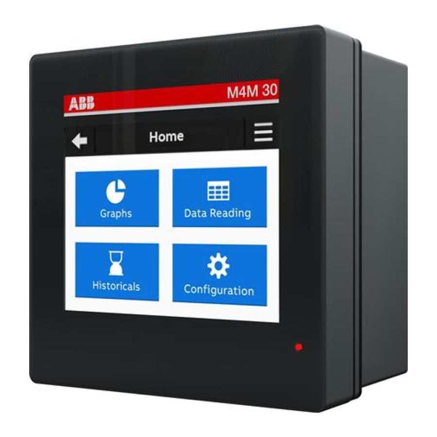
Access to device is done through touch screen. The home page is divided in four sections:
| Sections | Description |
| Graphs | Graphical representation of the main parameters. |
| Data Reading | Value of the main parameters. |
| Historicals | Values recorded in the flash memory. |
| Configuration | Setup of the device. |
First Commissioning
To start to use the analyzer it is mandatory to configure the basic setting: a wizard will guide the user for the configurations (lanuage, password, date&time, type of network, CT ratio and VT ratio).
Setting language
 → Unit → Language
Select the desired language for the display among the ones available.
Setting password

At first use, the password shall be defined. In order to disable the password, please enter 00000.
M4M 30-M only: It is not possible to disable password. The password protects all configurations that are not critical. Critical configurations are protected by the Lock (see 5.7).
Setting Date/Time
 → Unit → Date&Time
Set the current date (format: YYYY/MM/DD) and current time.
Type of network
Select the type of network among the following ones
 → Installation → Type of network
| Parameter | Description |
| 3Ph/4W/4CT | 3-phase 4-wire + 4CTs |
| 3Ph/4W/3CT | 3-phase 4-wire + 3CTs |
| 3Ph/4W/1CT | 3-phase 4-wire + 1CT |
| 3Ph/3W/1CT | 3-phase 3-wire + 1CT |
| 3Ph/3W/3CT | 3-phase 3-wire + 3CTs |
| 3Ph/3W/2CT | 3-phase 3-wire + 2CTs |
| 2Ph/3W/2CT | 2-phase 3-wire + 2CTs |
| 1Ph/2W/1CT | 1-phase 2-wire + 1CT |
Only configuration market with M are MID compliant on M4M 30-M

Current Transformer ratio
Select the current transformer Ratio among the default ones or enter it manually.
 → Installation → CT ratio

In case of manual entry, enter the value of the primary with + or - and select the secondary (1A or 5A).

If a 4th CT is used, CT ratio for Neutral has to be configured.
Voltage Transformer ratio
Enter the voltage transformer ratio (both primary and secondary) manually with + or -
 → Installation → VT ratio

In case of direct insertion, 400/400V value shall be used.
Lock (M4M 30-M MID)
To comply with MID, after Type of network, CT ratio, VT ratio are set, the M4M must be put in Lock state.
These parameters cannot be modified after lock operations.
M4M 30-M will not count any MID energy until Lock is completed.
Technical data
| Auxiliary power supply | |
| Voltage range [V] | 48 - 240 VAC/VDC ±15% |
| Frequency [Hz] | 50/60 Hz |
| Power consumption | 10 VA max |
| Installation category | CAT III 300V class per IEC 61010-1 edition 3 |
| Protection fuse | T1 A - 277 VAC |
| Measurement accuracy | |
| IEC 61557-12 | IEC 61557-12 PMD/S/K70/0.5 |
| Active energy | Class 0,5S acc. to IEC 62053-22 |
| Active power | Class 0,5 acc. to IEC 61557-12 |
| Reactive power | Class 2 acc. to IEC 61557-12 |
| Voltage | Class 0,2 acc. to IEC 61557-12 |
| Phase Current | Class 0,2 acc. to IEC 61557-12 |
| Voltage measurement inputs | |
| Measurement range [V] | 46(80)...480(830) V |
| Measurement cat. | 400V~ (CAT III) |
| Rated frequency [Hz] | 50-60 Hz |
| Protection fuse | T1 A - 277 VAC |
| Current measurement inputs | |
| N. of current inputs | 4 (L1, L2, L3, N) |
| CT rated sec. current | 5 A or 1 A |
| Measurement range without accuracy derating | 50 mA - 6 A |
| Starting current [mA] | 5 mA |
| I/O | |
| Digital Output | |
| Voltage (min - max) | 5 - 240 VAC/DC |
| Current (min - max) | 2 - 100 mA |
| Digital Input | |
| Maximum Voltage | 240 VAC/DC |
| OFF | 20 VAC/DC |
| ON | 45 VAC/DC |
| Analogue Output | |
| Programmable electrical parameters | Span [0 - 20 mA or 4 - 20 mA] |
| Load | Typical 250 Ohm, max 500 Ohm |
| Terminal characteristics | |
| Nominal cross section Solid/stranded wire | 2,5 mm 2 0,2 - 2,5 mm2 (AWG 24 - 12) |
| Pitch | 5,08 mm |
| Operating conditions | |
| Operating temperature | -25 to 70°C |
| Storage temperature | -40 to 85°C |
| Relative humidity | Max 93% (non-condensing) at 40°C |
| Pollution degree | 2 |
| Altitude | < 2000 m |
| IP degree of protection | Front: IP54 |
| (IEC 60529) | Terminals: IP20 and IP54 if in protective enclosure |
| Mounting requirement | Only for internal usage |
| Technical data for M4M 30-M according to the Measuring Directive 2014/32/EU | |
| MID standards | EN 50470-1 EN 50470-3 |
| Voltage measurement (type of network and rated voltage)" | 33Ph/4W/4CT 3Ph/4W/3CT 3Ph/3W/2CT 1Ph/2W/1CT 3 x 230 (400)...3 x 400 (690) V |
| Current rating (I min- I ref(Imax)) | 0,01-1(6) A |
| Rated frequencies | 50 Hz and 60 Hz |
| Active Energy accuracy class | Class C |
| Electromagnetic ambient conditions | Class E2 |
| Mechanical ambient conditions | Class M1 |
| LED indicator pulse frequency | 200000 imp/kWh |
| LED indicator pulse length | 1ms |
| Warranty and accuracy are void if sealing is removed. Firmware upgrade shall be performed during a low consumption period. | |
Disclaimer
The information in this document is subject to change without notice and should not be construed as a commitment by ABB. ABB assumes no responsibility for any errors that may appear in this document.
In no event shall ABB be liable for direct, indirect, special, incidental or consequential damages of any nature or kind arising from the use of this document, nor shall ABB be liable for incidental or consequential damages arising from use of any software or hardware described in this document.

Working with high voltage is potentially lethal. Persons subjected to high voltage may suffer cardiac arrest, burn injuries, or other severe injuries. To avoid such injuries, make sure to disconnect the power supply before you start the installation. Electrical equipment should only be installed, accessed, serviced and maintained by qualified electrical personnel.
For safety reasons it is recommended that the equipment is installed in a way that makes it impossible to reach or touch the terminal blocks by accident.
The best way to make a safe installation is to install the unit in an enclosure. Further, access to the equipment should be limited through use of lock and key, controlled by qualified electrical personnel.
The power meters must always be protected by fuses on the incoming side. In order to allow for maintenance of transformer rated meters, it is recommended that there should be a short circuiting device installed near the meter. Do not operate the equipment outside the specified technical data.
Service and Maintenance
The power meter contains no parts that can be repaired or exchanged. A broken meter must be replaced. If the meter needs to be cleaned, use a lightly moistened cloth and a mild detergent to wipe it.

Be careful that no liquid gets into the meter since it may damage the equipment.
Contact us
ABB S.p. A.
Electrification Business
Viale dell'Industria, 18
20009 Vittuone (MI) Italy
https://new.abb.com/low-voltage

Installation by person with electrotechnical expertise only.
© Copyright 2021 ABB S.p. A. All rights reserved. Specification subject to change without notice.

Documents / Resources
References
Download manual
Here you can download full pdf version of manual, it may contain additional safety instructions, warranty information, FCC rules, etc.
Advertisement
Thank you! Your question has been received!


Need Assistance?
Do you have a question about the M4M 30 that isn't answered in the manual? Leave your question here.