Table of Contents
Advertisement
Quick Links
Advertisement
Table of Contents

Related Manuals for ABB M4M 30


Summary of Contents for ABB M4M 30
- Page 1 Network Analyzer M4M 30 User manual...
-
Page 3: Table Of Contents
M4M 30 NETWORK ANALYZER USER MANUAL Table of Contents 1.General information....................5 1.1.Use and storage of the manual ................5 1.2.Copyright ........................5 1.3.Liability disclaimer ....................5 1.4.General safety warnings ..................5 1.5.Cyber Security Disclaimer ..................6 2.Packaging contents ....................7 3.Technical characteristics ..................8 3.1.Description of the device ..................8 3.2.Main functionalities ....................8... - Page 4 M4M 30 NETWORK ANALYZER USER MANUAL 7.4.Input / output ...................... 48 7.5.Alarms........................50 7.6.Complex alarms .....................51 7.7.Tariffs ........................52 7.8.Communication ....................54 7.9.Other settings ......................57 8.Data Reading .......................60 8.1.Realtime ........................61 8.2.Energy ........................62 8.3.Power Quality ....................... 64 8.4.Average ........................65 8.5.Min Value ......................66 8.6.Max Value ......................67...
-
Page 5: General Information
The information contained in this document is subject to change without notice and cannot be considered as an obligation by ABB S.p.A. ABB S.p.A. is not liable for any errors that may appear in this document. ABB S.p.A. is not liable under any circumstances for any direct, indirect, special, incidental or consequential damage of any kind that may arise from using this document. -
Page 6: Cyber Security Disclaimer
ABB S.p.A. and its affiliates are not liable for damages and/ or losses related to such security breaches, unauthorized access, interference, intrusion, leakage and/or theft of data or information. -
Page 7: Packaging Contents
(3 poles) (3 poles) M4M 30 MODBUS M4M 30 ETHERNET M4M 30 PROFIBUS M4M 30 I/O M4M 30 BACNET M4M 30 ROGOWSKI Please notice that terminals for current input on M4M 30 Rogowski are pre-wired on ABB’s R4M Rogowski coils... -
Page 8: Technical Characteristics
M4M 30 is ABB’s network analyzer range that allows complete power quality analysis and energy efficiency evaluations. All M4M 30 network analyzers are equipped with touchscreen color display for simplified access to the device and with Bluetooth module for smart commissioning. -
Page 9: Versions
M4M 30 NETWORK ANALYZER USER MANUAL 3.3.Versions Product Name Communication protocol M4M 30 MODBUS 4 programmable I/O Modbus RTU, Bluetooth M4M 30 ETHERNET 4 programmable I/O Modbus TCP/IP, Bluetooth M4M 30 PROFIBUS 4 programmable I/O Profibus DP-V0, Bluetooth 6 programmable I/O,... -
Page 10: Technical Data
M4M 30 NETWORK ANALYZER USER MANUAL 3.5.Technical data Auxiliary power supply Voltage range 48 to 240 VAC/VDC ±15% Frequency [Hz] 50/60 Hz ±5% Power Consumption [VA] 10 VA max Installation category CAT III 300V class per IEC 61010-1 edition 3... - Page 11 Pitch: 5,08 mm Poles: 5 (Programmable I/O) Poles: 3 (Programmable I/O only on M4M 30 I/O) Poles: 3 (Analogue outputs, only on M4M 30 I/O) Only with ABB Rogowski probes: Rogowski current probes -R4M-200: 200 mm diameter (2CSG202150R1101) -R4M-80: 80 mm diameter (2CSG202160R1101)
- Page 12 Display type Graphic color display Display dimensions 70 x 52 mm (3.5") Communication protocol Modbus RTU M4M 30 Modbus, M4M 30 I/O, M4M 30 Rogowski Communication interface RS485 with optical isolation Baud rate 9.6, 19.2, 38.4, 57.6, 115.2 kbps Parity number...
-
Page 13: Installation
M4M 30 NETWORK ANALYZER USER MANUAL 4.Installation 4.1.Assembly 4.2.Disassembly... -
Page 14: Wiring Diagrams
M4M 30 NETWORK ANALYZER USER MANUAL 4.3.Wiring diagrams The operations to carry out for the correct connection of the device, based on the type of electric line available, are described in this section. The installation and the cabling of the device must be carried out by qualified personnel. - Page 15 M4M 30 NETWORK ANALYZER USER MANUAL • M4M 30 I/O connection • M4M 30 BACNET connection • M4M 30 ROGOWSKI connection...
- Page 16 Wiring diagrams - M4M 30 Modbus, M4M 30 Ethernet, M4M 30 I/O, M4M 30 Profibus, M4M 30 Bacnet The M4M 30 can be used on different type of network (please refer to chapter “” for the configuration on the device).
- Page 17 • 2-phase 3-wire network with 2CTs • 1-phase 2-wire network with 1CT Wiring diagrams - M4M 30 Rogowski Below the wiring diagrams for M4M 30 working with Rogowski coils are shown: • 3-phase 4-wire network with 4RogCTs • 3-phase 4-wire network with 3RogCTs...
- Page 18 M4M 30 NETWORK ANALYZER USER MANUAL • 2-phase 3-wire network with 2RogCTs • 3-phase 3-wire network with 3RogCTs • 3-phase 3-wire network with 2RogCTs • 3-phase 4-wire network with 1RogCT • 1-phase 2-wire network with 1RogCT • 3-phase 3-wire network with 1RogCT...
- Page 19 B: Pulse acquisition (Impulse length at least 30 mS ) Same wiring schemes apply for I/O5 and I/O6 available only on M4M 30 I/O. • Analogue outputs, typical load 250 Ohm, max 500 Ohm (available only on M4M 30 I/O):...
-
Page 20: Access To Device
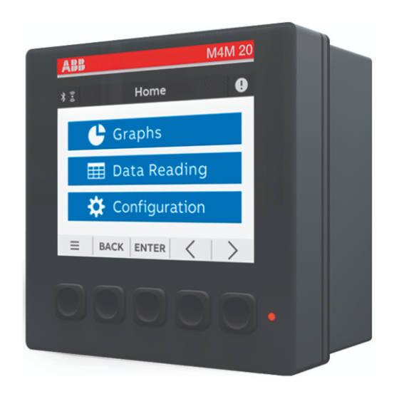
M4M 30 NETWORK ANALYZER USER MANUAL 5.Access to device 5.1.Homepage The device menu is divided into four sections. Menu Description Graphs Graphical representation of the main measured parameters. Data reading Reading of the main measured parameters. Historicals Reading of the measured parameters recorded in the flash memory. -
Page 21: Navigation Symbols
M4M 30 NETWORK ANALYZER USER MANUAL 5.2.Navigation symbols Symbol Description Shortcut key with 3 sections: Notifications, Favourite page and Home. Return to the previous page. Increase or decrease the value. Keeping pressed will increase the speed of the number variation. -
Page 22: Overview Of Menu
M4M 30 NETWORK ANALYZER USER MANUAL 5.4.Overview of menu pages Each section of the device contains different menus and submenus as per below tables: → Menu Description Bargraphs for voltage (L-N, L-L), current, power (active, reactive, Realtime Graphs apparent). Waveforms Waveforms visualization for voltage (L-N, L-L), current. -
Page 23: Data Entry
M4M 30 NETWORK ANALYZER USER MANUAL → Menu Description Unit Settings related to the device itself. Installation Settings related to the installation conditions. Historicals Settings related to Historicals functionalities, stored on the flash memory. Definition of I/O type of the M4M version. - Page 24 M4M 30 NETWORK ANALYZER USER MANUAL Confirmation pop-up For some configurations of the device it is mandatory to give further confirmation after data entry. A confirmation pop-up is shown on the screen: 1a. Press Confirm to confirm the modification. 1b. Press Cancel to return to previous page.
-
Page 25: Favourite Page
M4M 30 NETWORK ANALYZER USER MANUAL 5.6.Favourite page It is possible set a page as a “Favourite page”, that is then easily accessible by clicking the“Favourite” key. Setting - Favourite page 1. Enter the page you would like to set as favourite 2. -
Page 26: First Commissioning
M4M 30 NETWORK ANALYZER USER MANUAL 6.First commissioning At first power up of M4M network analyzers, wizard procedure will guide the user in the first commissioning steps: 1. Set the language (please refer to chapter “6.1.Language”) 2. Set a password (please refer to chapter “6.2.Password for the first use”) 3. -
Page 27: Date And Time
M4M 30 NETWORK ANALYZER USER MANUAL 6.3.Date and time Setting date and time is mandatory in order to use the time-related functionalities on the device (e.g. Historicals, Maximum, Minimum). Please notice that if no date and time are set, no timestamp will be available on the measured data. -
Page 28: Ct Ratio
6.5.CT ratio M4M is capable to measure current only via indirect connection by means of current transformers CTs.../5A or .../1A (M4M 30 Modbus, M4M 30 Ethernet, M4M 30 I/O, M4M 30 Profibus, M4M 30 Bacnet), or Rogowski coils (M4M 30 Rogowski). - Page 29 2. Reset the energy counts. 3. Insert a new value of the transformation ratio. Please notice that if M4M 30 Rogowski is being used, no CT ratio has to be set for Rogowski coils. Primary of CT has to be higher than the secondary.
-
Page 30: Vt Ratio
Default values are the same as for CT ratio L1 L2 L3. In case of manual entry, please refer to the manual entry of CT ratio L1 L2 L3. Please notice that if M4M 30 Rogowski is being used, no CT ratio has to be set for Rogowski coils. 6.6.VT ratio M4M is capable to measure voltage via direct connection up to 400 VL-N (690V L-L), or via indirect connection by means of voltage transformers. -
Page 31: Configuration
M4M 30 NETWORK ANALYZER USER MANUAL 7.Configuration In order to change any configuration of the device, it is mandatory to enter the password. The password is valid as soon as the user remains in the Configuration section and for max. 10 minutes. After quitting the Configuration section, it is needed to enter again the password. - Page 32 M4M 30 NETWORK ANALYZER USER MANUAL Modify password menu In order to modify the password: → → → Unit Modify Password 1. Dismiss the “Insert the old password” popup. 2. Enter the current password (“Old password” on the screen) and confirm the selection with Confirm;...
- Page 33 Please check the ABB website and download the latest version of the firmware. In order to update the FW to the latest version (via Modbus RTU or Modbus TCP/IP) it is necessary to use ABB Software Ekip Connect 3.
- Page 34 M4M 30 NETWORK ANALYZER USER MANUAL Brightness menu In this menu it is possible to modify the display brightness during normal operation conditions. → → → Unit Brightness The default value is 100% but it can differ from 10% to 100%.
-
Page 35: Installation
M4M 30 NETWORK ANALYZER USER MANUAL Logs menu The Audit Log stores an event after an attempt has been made to upgrade the firmware and/or CT ratio, VT ratio or Type of network is modified. → → → Unit Logs... - Page 36 M4M 30 NETWORK ANALYZER USER MANUAL CT ratio L1 L2 L3 menu During the first commissioning, it is highly recommended to configure the CT ratio L1, L2, L3 and Neutral (please refer to chapter “6.5.CT ratio”). → → → Installation...
- Page 37 M4M 30 NETWORK ANALYZER USER MANUAL Type of network menu During the first commissioning, it is highly recommended to configure the Type of network (please refer to chapter “6.4.Type of network”). → → → Installation Type of network LED Source menu It is possible to choose the source of LED among the following options: Active, Reactive ad Apparent energy.
-
Page 38: Historicals
M4M 30 NETWORK ANALYZER USER MANUAL 7.3.Historicals In this section it is possible to carry out configurations related to Historicals functionalities. Historicals functionalities allow to store measurements (instantaneous snapshots, demand values) inside the device flash memory. → → Historicals Menu... - Page 39 M4M 30 NETWORK ANALYZER USER MANUAL Load profile menu Load profile functionality allows to calculate the demand value of main real time measured quantities like voltage, current, power and THD, calculated over a specific time interval. These demand values are then visualized in a load profile curve in order to check the trend of the real time quantities.
- Page 40 M4M 30 NETWORK ANALYZER USER MANUAL • Channels It is possible to configure each channel to one of the following parameters, allowing to store one parameter in each channel. Up to 25 parameters can be selected and stored. Default parameters are already configured and defined in the M4M for each channel, see details below.
- Page 41 M4M 30 NETWORK ANALYZER USER MANUAL Max/Min Demand menu Max/min demand functionality is used to measure and store in the product flash memory the maximum and minimum demand values referred to a specific time period (day, week, month) of main real time measured.
- Page 42 M4M 30 NETWORK ANALYZER USER MANUAL • Time interval The time interval is in common for all the max/min demand channels. For this reason, this configuration has to be done only once. Average values can either be calculated with sliding demand or no sliding.
- Page 43 M4M 30 NETWORK ANALYZER USER MANUAL • Time period The time period is in common for all the max/min demand channels. For this reason, this can configuration has to be done only once. The time period represents the timeframe over which the max/min demand values are evaluated and then stored.
- Page 44 M4M 30 NETWORK ANALYZER USER MANUAL • Channels It is possible to link each channel to one of the following parameters, allowing to store one parameter in each channel. Up to 25 parameters can be selected and stored. Default parameters are already setup in the M4M for each channel, see details below.
- Page 45 M4M 30 NETWORK ANALYZER USER MANUAL Energy Historicals menu Configuration of energy historicals is linked to two different functionalities: Energy Snapshots allows to obtain instantaneous energy snapshots taken in each time interval, and Energy Trend allows to obtain the difference between the energy values at the end and at the beginning of each time interval. At the end of a defined time interval, up to 20 energy parameters are stored together with the timestamp.
- Page 46 M4M 30 NETWORK ANALYZER USER MANUAL • Time interval The time interval is in common for all the channels of memory. For this reason, this can configuration has to be done only once. → → → → Historicals Energy historicals...
- Page 47 M4M 30 NETWORK ANALYZER USER MANUAL • Channels It is possible to link each channel to one of the following parameters, allowing to store one parameter in each channel. Up to 20 parameters can be selected and stored. Default parameters are already setup in the M4M for each channel, see details below.
-
Page 48: Input / Output
M4M 30 NETWORK ANALYZER USER MANUAL 7.4.Input / output In this section it is possible to configure I/O slots of the meter. The number and type of I/O on the M4M network analyzer varies according to the different product versions. Please refer to the table in “3.3.Versions” for the detail of I/O types per each M4M. - Page 49 Selecting Output OFF, the output status is always set Low. • Analog output Slots 7 and 8 of the I/O menu for M4M 30 I/O contain analog outputs that can be used to associate a measured parameter to a current output value.
-
Page 50: Alarms
M4M 30 NETWORK ANALYZER USER MANUAL 7.5.Alarms In this section it is possible to configure the single alarms, allowing to monitor certain value selected from a list of parameters. → → Alarms When specific conditions are met, alarms is turned on or off. Triggering of alarms can be registered in the devices notifications log, in the alarms section. -
Page 51: Complex Alarms
M4M 30 NETWORK ANALYZER USER MANUAL In order to set an alarm, it is needed to define the parameter associated to the alarm, the alarm type (cross up over threshold, or cross down under threshold), the threshold value for the parameter, the activation delay and the hysteresis for the turn off threshold. -
Page 52: Tariffs
M4M 30 NETWORK ANALYZER USER MANUAL 7.7.Tariffs In this section it is possible to configure up to six tariffs to monitor consumption in different time frames. It is possible to control activation via: clock, setting up to three input channels and settings sent via bus. - Page 53 M4M 30 NETWORK ANALYZER USER MANUAL • Clock → → → Tariffs Clock Selecting Clock, it is possible to define when the different tariffs are active, according to specific day and hour, driven by Real Time Clock. After selecting a tariff (6 tariffs available), it is needed to configure the type of day of the tariff - during the week or during the weekend.
-
Page 54: Communication
M4M 30 NETWORK ANALYZER USER MANUAL 7.8.Communication → → Communication Communication menu allow to set all the parameters related to the communication protocol available for a specific product version. The embedded communication protocol varies according to the different product versions. Please refer to “3.3. Versions” for the details on the embedded communication protocols. - Page 55 MODBUS RTU (M4M 30 Modbus, M4M 30 I/O, M4M 30 Rogowski product versions) This section is available on all the M4M 30 product versions with Modbus RTU embedded communication. →...
- Page 56 M4M 30 NETWORK ANALYZER USER MANUAL PROFIBUS (M4M 30 Profibus product version) This section is available on M4M 30 Profibus with Profibus DP-V0 embedded communication. → → Communication → Profibus Menu Description Address From 1 to 126 If DHCP is disabled, the values of above configurations (IP address, subnet mask, gateway, TCP port) are the default ones.
-
Page 57: Other Settings
M4M 30 NETWORK ANALYZER USER MANUAL 7.9.Other settings In this menu it is possible to configure the time interval for average values calculation, timers settings, energy conversion parameters. → → Other settings Menu Description Average Configuration of time interval for Average values. - Page 58 M4M 30 NETWORK ANALYZER USER MANUAL Timers menu In this menu it is possible to configure the count-down timer, used for maintenance notification, and the timers reset. For the data reading of timers values please refer to chapter “8.9.Timers”. →...
- Page 59 M4M 30 NETWORK ANALYZER USER MANUAL Warning levels menu In this menu it is possible to configure the limit value for single harmonics (% of the fundamental) that can be then displayed in the harmonics graphs. Once the warning level threshold is exceeded, the visualization of the harmonic graph bar will turn to orange color.
-
Page 60: Data Reading
M4M 30 NETWORK ANALYZER USER MANUAL 8.Data Reading Data reading section allows to visualize all the parameters measured by M4M. → Press to return to the home page. -
Page 61: Realtime
M4M 30 NETWORK ANALYZER USER MANUAL 8.1.Realtime → → Realtime Visualization page Description 3-phase voltage (line to line), 3-phase current, total active Summary power. Line to neutral voltage per phase and 3-phase line to line Line-Neutral voltage voltage. Line-Line voltage Line to line voltage per phase and 3-phase line to line voltage. -
Page 62: Energy
M4M 30 NETWORK ANALYZER USER MANUAL 8.2.Energy → → Energy Visualization page Active Energy - Import Total imported active energy in Wh/kWh/MWh. Reactive energy - Import Total imported reactive energy in varh/kvarh/Mvarh. Apparent energy - Import Total imported apparent energy in VAh/kVAh/MVAh. - Page 63 M4M 30 NETWORK ANALYZER USER MANUAL Tariffs → → → Energy Tariffs Move with keys to navigate among the visualization pages. Press to return to the home page.
-
Page 64: Power Quality
M4M 30 NETWORK ANALYZER USER MANUAL 8.3.Power Quality → → Power Quality Visualization page Description THD Line-Neutral voltage Per phase line to neutral voltage THD values. THD Line-Line voltage Per phase line to line voltage THD values. THD Current Total and per phase current THD values. -
Page 65: Average
M4M 30 NETWORK ANALYZER USER MANUAL 8.4.Average → → Average Visualization page Description Average per phase line to neutral voltage calculated for a Average Line-Neutral Voltage defined period of time (default: 15 minutes). Average per phase line to line voltage calculated for a Average Line-Line Voltage defined period of time (default: 15 minutes). -
Page 66: Min Value
M4M 30 NETWORK ANALYZER USER MANUAL 8.5.Min Value → → Min Value Visualization page Description Minimum Line-Neutral Voltage Minimum per phase line to neutral voltage measured value. Minimum Line-Line Voltage Minimum per phase line to line voltage measured value. Minimum Current (L1, L2, L3) Minimum per phase measured current. -
Page 67: Max Value
M4M 30 NETWORK ANALYZER USER MANUAL 8.6.Max Value → → Max Value Visualization page Description Maximum Line-Neutral Voltage Maximum per phase line to neutral voltage measured value. Maximum Line-Line Voltage Maximum per phase line to line voltage measured value. Maximum Current (L1, L2, L3) Maximum per phase measured current. -
Page 68: I/O
M4M 30 NETWORK ANALYZER USER MANUAL 8.7.I/O The number and type of I/O on the M4M network analyzer varies according to the different product versions. Please refer to the table in “3.3 Versions” for the detail of I/O types per each M4M. -
Page 69: Notifications
M4M 30 NETWORK ANALYZER USER MANUAL 8.8.Notifications → → Notifications Menu item Description All alarms, warnings, errors displayed in chronological order (latest first). Alarms User settable, related to specific parameters, threshold, etc. Warnings Related to installation conditions and device settings. - Page 70 M4M 30 NETWORK ANALYZER USER MANUAL Alarms → → → Notifications Alarms If one of the alarms is selected, timestamp (Day, Hour) will be shown. Day format is YYYY:MM:DD, time format is hh:mm:ss. Warnings → → → Notifications Warnings If one of the warnings is selected, timestamp (Day, Hour) will be shown. Day format is YYYY:MM:DD, time...
-
Page 71: Timers
M4M 30 NETWORK ANALYZER USER MANUAL Errors → → → Notifications Errors 8.9.Timers → → Timers Menu Description Represents the timer count up of the device lifetime since the Up counter power up. Down counter Represents the timer count down for the device maintenance. -
Page 72: Historicals
M4M 30 NETWORK ANALYZER USER MANUAL 9.Historicals In the Historicals section it is possible to read out the parameters stored in the device flash memory (32 MB). Each feature has a predefined number of parameters that can be stored in each channel of flash memory. -
Page 73: Max/Min Demand
M4M 30 NETWORK ANALYZER USER MANUAL 9.2.Max/min demand Visualization of the maximum and minimum values for 25 different parameters. Select a time period to view in the list of the available periods. Each page shows up to 3 levels of max and/or 3 levels of min demand values linked to the channel of memory, according to the configuration that has been carried out. -
Page 74: Energy Trend
M4M 30 NETWORK ANALYZER USER MANUAL 9.4.Energy Trend Visualization of energy trends graphs for 20 different parameters. Each page shows the graph of the latest 12 stored energy values in the defined time interval (differences between value at the end and at the beginning of time interval). The bottom part shows what parameter is linked to the channel and what is the time interval used to take the two snapshots for the trend definition. -
Page 75: Graphs
M4M 30 NETWORK ANALYZER USER MANUAL 10.Graphs In the Graphs section it is possible to visualize the main parameters measured by M4M in a graphical view. → Press to return to the home page. -
Page 76: Realtime
M4M 30 NETWORK ANALYZER USER MANUAL 10.1.Realtime Bargraphs showing in an intuitive way the realtime values of voltage, current and power. The graphs are automatically scaled according to the values that are measured in realtime. → → Realtime Graph Line-Neutral voltage... -
Page 77: Waveforms
M4M 30 NETWORK ANALYZER USER MANUAL 10.2.Waveforms Waveforms consists in storing signal samples over 2 line cycles for voltage and current. This functionality provides a realtime snpashot of network condition. → → Waveforms Waveforms Description Visualization of waveform graphs for line to neutral voltage per each L-N Voltage phase. - Page 78 M4M 30 NETWORK ANALYZER USER MANUAL L-L Voltage Waveforms → → → Waveforms L-L Voltage Graphs Line-Line Voltage (L12) Line-Line Voltage (L23) Line-Line Voltage (L31) Move with to change the line to line voltage (L12, L23, L31). Current waveforms →...
-
Page 79: Harmonics
M4M 30 provides harmonic distortion metering up to the 40th harmonic, which are available on communication protocol. On the HMI in this section it is possible to visualize the first 15 harmonics as graphs, where the vertical axis of the harmonics graph indicates the harmonic’s magnitude as a percentage of the fundamental... - Page 80 M4M 30 NETWORK ANALYZER USER MANUAL Line-Neutral Voltage harmonics The vertical axis of the harmonics graph indicates the harmonic’s magnitude as a percentage of the fundamental harmonic, and is scaled based on the largest harmonic displayed. → → → Harmonics...
-
Page 81: Phasors
M4M 30 NETWORK ANALYZER USER MANUAL Current harmonics → → Harmonics → Current Graph Current (L1) Current (L2) Current (L3) Current (N) Move with to change the current harmonics graphs visualization (L1,L2,L3,N). 10.4.Phasors → → Phasors Visualization pages Description Phase relationship of voltage and current for each phase. Voltages Diagram are displayed with arrows and currents with solid lines. - Page 82 ......................................................................................................................................................................................................................................................................................................................................................................................................................................................................................................................................................................................................................................................................................................................................................................................................................................................................................................................................................................................................................................................................................................................................................................................................................................................................................................................................................................................................................................................................................................................................................................................................................................................................................................
- Page 84 ABB S.p.A Electrification business Viale dell’Industria, 18 20010 Vittuone (MI) Italy new.abb.com/low-voltage...