Advertisement
Quick Links
IED 670
en05000411.vsd
Figure 1: Flush mounting.
Figure 2: Mounting plates for side-by-side and the
mounting brackets and flush mounting kit.
Note! Ensure that the case is properly
earthed.
1MRK 500 080-UEN rev. -
Mounting and installation
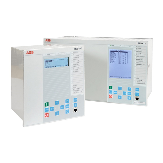
The 670 IEDs are 6U high (265.9 mm) and are available in 1/2, 3/4 and 1/1 case
sizes for 19" racks. All IEDs fit into a 19" rack with the help of alternative
cover plates or with COMBIFLEX relays/cases, of type RHGS6 and RHGS12.
The mounting details are: side by side mounting plates (1) 1MRK 002 420-Z
when two relays or a relay and relay rack are mounted together. Mounting
brackets for a full 19" (2) 1MRK 002 420-CA. Cover plates with brackets for
19" mounting for 3/4 case size 1MRK 002 420-BA, and for 1/2 case size
1MRK 002 420-BB.
Alternatively the IED can be flush mounted. The IED can be ordererd with
optional IP 54 ingression protection.
Test switches and COMBIFLEX auxiliary relays can be mounted in separate
relay cases. The RHGS6 and RHGS12 types of cases can be used and bolted
together with the IED 670 to fill a relay rack. If the RTXP24 test switch is used,
mounting brackets for apparatus bars, ordering No. 1MRK 000 020-BT are
required. A suitable test switch with contacts for example for a line protection
IED such as REL 670 is selectable when ordering. This allows commissioning
and maintenance testing of the complete IED with many functions from one test
handle.
Note! The use of test switch RTXP24 NO contact 29-30 to perform software
blocking has several advantages and is used during testing of many functions in
the same protection IED.
Test is supported by the configuration TEST function block. Switching the IED
to test mode will allow blocking and releasing of individual functions sepa-
rately and also blocking of events to the SA system.
For test system references refer to Buyers guide 1MRK 512 001-BEN COM-
BITEST. For Dimensions, mechanical design and mounting accessories refer to
Buyers Guides 1MRK 514 003-BEN and 1MRK 514 004-BEN.
Builder's guide 1MRK 500 079-MEN provides information regarding how to
use the IED's in actual SA installations.
xx04000447.vsd
Getting started guide
1
Advertisement

Summary of Contents for ABB IED 670
- Page 1 The RHGS6 and RHGS12 types of cases can be used and bolted together with the IED 670 to fill a relay rack. If the RTXP24 test switch is used, mounting brackets for apparatus bars, ordering No. 1MRK 000 020-BT are required.
- Page 2 X11:2 + Supply (IRF). which includes diagrams (schematics) of the electrical connections to the X11:3 Fail, Binary output (IRF). IED 670. X11:4 PSM + connector for DC supply. X11:5 PSM - connector for DC supply. 10. Binary output no.13 on a BOM.
- Page 3 The Human Machine Interface The IED 670 products can be ordered with a small or medium HMI module. Both have a LED panel and a serial communication port on the front panel. The Parameter Setting Tool in PCM 600 toolbox installed on a PC is used to set parameters via the serial port.
- Page 4 On the medium HMI display, the single line diagram can be presented and shows apparatuses that can be controlled locally using the control buttons. To safeguard the interests of our customers, both the IED 670 and the tools that are accessing the IED 670 are protected, subject of authorization handling. The...
- Page 5 4. Peer-to-Peer communication is made possible using both IEC 61850-8-1 with GOOSE and LON. In the IED 670 IED the incoming signals (LON) are set up with a Command block (Cmd) and the outgoing signals with an Event block (Ev) when the unit is config- ured.
- Page 6 Configuring the IED 670 functions Start-up The PCM 600 toolbox is used to configure protection IEDs in the IED 670 series. The tool includes a project manager and tools for all necessary tasks. Install the PCM 600 in your computer first and then install the IED connectivity packages.
- Page 7 PCM 600 toolbox. Configuration Configure the IED with the CAP 531 Application configuration tool. The default password is abb. Right click on IED and select Application Configura- tion. The PCM 600 toolbox can be used to upload the ordered default configuration...
- Page 8 Signal Matrix Tool (SMT) The SMT connects the virtual IO to the physical IO. This offers high flexibility without the need to adjust the configuration. When a configuration has been completed with the Application configuration tool CAP 531, the Signal Matrix tool can be opened.
- Page 9 Disturbance recorder handling The IED 670 includes a Disturbance recorder (DR) with 40 analog and 96 digi- tal channels. It has a default configuration and signals have been given names which will show-up on the records.
-
Page 10: Application Functions
Many of these are included as basic in the “ready-to-use” IED. The IED is delivered with a basic configuration that includes default parameter settings. This simplifies the initial start-up of the IED. In the IED 670 series the following examples are preconfigured default functions, included and set to typical values: Id >... -
Page 11: Fault Finding
Fault finding A flashing green LED indicates an internal fault. Check the IED Status menu to find the problem. A flashing yellow LED indicates that the IED is in Test mode. Navigate to the Test menu and switch the Operation - Off. When the yellow LED is on and shines steadily a protection function has started and a distur- bance report has been generated When a red LED shines–... -
Page 12: Related Documents
1MRS755552 Builder’s Guide 1MRK 500 079-MEN ABB AB Substation Automation Products If you require further assistance, contact your local ABB support or ABB support line. SE-721 59 Västerås Tel: +46 21 342500, e-mail: sa-t.supportline@se.abb.com, fax +46 21 146918, Sweden Phone:...


