Table of Contents
Advertisement
Quick Links
—
A B B M E A S U R E M E N T & A N A LY T I C S | U S E R G U I D E | O I/ F E T 2 0 0 - E N R E V. N
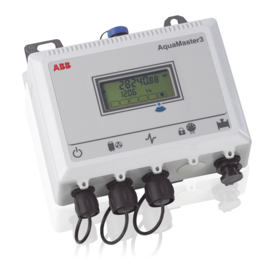
AquaMaster 3 FET200
Electromagnetic flowmeter
transmitter
—
Introduction
AquaMaster 3
FET200
Electromagnetic
AquaMaster 3
flowmeter
performance electromagnetic flowmeters
transmitter
for the measurement of electrically-
conductive fluids and is normally supplied
as factory-configured, calibrated systems.
This User Guide provides end-user details
for AquaMaster 3 close-coupled and remote
transmitters.
When the meter is taken out of storage and
installed for first use, remove the protective
label (if fitted) from the front to enable light
to activate the unit.
If the meter is not powered, connect any
batteries or external supply as detailed in
this manual.
is a range of high
TM
The smart solution for
remote applications
Measurement made easy
For more information
Further publications are available for free
download from
www.abb.com/flow
scanning this code:
Search for or click on
Data Sheet
Electromagnetic flowmeter
Data Sheet
AquaMaster
Electronic water meter
or by
DS/FER200/
FEF200/FEV200–
EN
DS/AMAS-EN
Advertisement
Table of Contents

Related Manuals for ABB AquaMaster 3 FET200


Summary of Contents for ABB AquaMaster 3 FET200
- Page 1 A B B M E A S U R E M E N T & A N A LY T I C S | U S E R G U I D E | O I/ F E T 2 0 0 - E N R E V. N AquaMaster 3 FET200...
- Page 2 Related documents Search for or click on Programming Guide Electromagnetic flowmeter IMPORTANT NOTE For devices manufactured before February 2022, kindly refer to earlier revision of the user guide ( Revision M) – OI/FET200-EN Revision M...
-
Page 3: Table Of Contents
AquaMaster 3 FET200 Electromagnetic flowmeter Contents Safety and Security ......................... 3 Electrical Safety ............................. 3 Symbols ................................ 3 Security ................................. 3 Health & Safety ............................. 4 1.4.1 Battery Hazard, Handling, Shipping and Recycling / Disposal ............5 Waste Electrical and Electronic Equipment (WEEE) ..................5 Mechanical Installation ........................ - Page 4 AquaMaster 3 FET200 Electromagnetic flowmeter Appendix A – GSM-Equipped Units, Safety Precautions ..............37 Appendix B Accessories / Spares Kits ....................38 Common accessories ..........................38 Adapter Cable / Upgrade Kits ........................39 OI/FET200–EN Rev. N...
-
Page 5: Safety And Security
ABB Limited and its affiliates are not liable for damages and/or losses related to such security breaches, any unauthorized access, interference, intrusion, leakage and/or theft of data or information. -
Page 6: Health & Safety
AquaMaster 3 FET200 Electromagnetic flowmeter 1.4 Health & Safety Health and Safety To ensure that our products are safe and without risk to health, the following points must be noted: The relevant sections of these instructions must be read carefully before proceeding. -
Page 7: Battery Hazard, Handling, Shipping And Recycling / Disposal
AquaMaster 3 FET200 Electromagnetic flowmeter 1.4.1 Battery Hazard, Handling, Shipping and Recycling / Disposal Warning. AquaMaster is available with choice of battery technologies; Manganese Alkaline (part no WABC2100) or Lithium Thionyl Chloride (part no WABC2101 or WABC2102 or 'D' size cell). The following warnings... -
Page 8: Mechanical Installation
AquaMaster 3 FET200 Electromagnetic flowmeter 2 Mechanical Installation 2.1 Installation Conditions Close-coupled version – allow room to read data plate Fig. 2.1 Siting 60 °C –20 °C (140 °F) AquaMaster 3 (–4 °F) Maximum Minimum Fig. 2.2 Within Temperature Limits Fig. - Page 9 AquaMaster 3 FET200 Electromagnetic flowmeter <2 m 78 in.) AquaMaster 3 Submerged – 9 Months Accrued Time IP68 (NEMA 6P) ENCLOSURE 6P Not applicable to GSM Integral Aerial Installations – see Section 2.4.1, page 11 Fig. 2.6 Within Environmental Rating...
-
Page 10: Fitting The Vandal-Resistant Housing (Integral Transmitters Only)
AquaMaster 3 FET200 Electromagnetic flowmeter 2.2 Fitting the Vandal-Resistant Housing (Integral Transmitters Only) Referring to Fig. 2.9: 1. Slide cover over transmitter. 2. Insert bottom plate ensuring clips enter lugs 3. Secure with lock Fig. 2.9 Fitting Anti-Vandal Housing OI/FET200–EN Rev. N... -
Page 11: Dimensions
AquaMaster 3 FET200 Electromagnetic flowmeter 2.3 Dimensions 2.3.1 Remote- and Close-Coupled Transmitter Dimensions in mm (in.) 125 (5.0) 115 (4.50) (2.0) Ø 6.5 (0.25) 28 (1.1) Ø13 (0.50) AquaMaster 3 (5.4) 280 (11.0) with (7.3) Connectors 177 (7.0) Remote-mounted Transmitter... -
Page 12: Integral Transmitter And Vandal-Resistant Housing
AquaMaster 3 FET200 Electromagnetic flowmeter 2.3.2 Integral Transmitter and Vandal-Resistant Housing Dimensions in mm (in.) 244 (9.6) 175 (6.9) 220 (8.7) AquaMaster 3 Fig. 2.11 Integral Transmitter Dimensions Dimensions in mm (in.) 184 (7.2) 260 (10.2) Fig. 2.12 Vandal-resistant housing dimensions 2.3.3 External Battery Pack... -
Page 13: Gsm-Equipped Transmitters
AquaMaster 3 FET200 Electromagnetic flowmeter 2.4 GSM-Equipped Transmitters 2.4.1 GSM Antenna Installation Before deciding on an antenna mounting location, check that the local signal strength for the chosen mobile phone network is satisfactory. Use the GSM-equipped transmitter's integral signal strength test facility to establish signal strength. - Page 14 AquaMaster 3 FET200 Electromagnetic flowmeter Remote Antenna Integral Antenna 50 mm (2.0 in.) 50 mm (2.0 in.) AquaMaster 3 AquaMaster 3 Fig. 2.14 GSM Antenna Installation >50 mm (2.0 in.) Fig. 2.15 GSM Antenna Installation OI/FET200–EN Rev. N...
-
Page 15: Connecting A Remote Antenna
AquaMaster 3 FET200 Electromagnetic flowmeter 2.4.2 Connecting a Remote Antenna Referring to Fig. 2.16: 1. Remove the cover from the socket on top of the transmitter. 2. Gently push the antenna plug into the socket, then twist the screw ring clockwise until locked. - Page 16 AquaMaster 3 FET200 Electromagnetic flowmeter 7. Slide SIM card into holder , contact side down and bevelled edge to the top-right. 8. Close holder until it clicks into place and refit cover 9. Screw cover firmly in place. Note. Step 10 is applicable only to remote- and close-coupled transmitters.
-
Page 17: Electrical Installation
AquaMaster 3 FET200 Electromagnetic flowmeter 3 Electrical Installation 3.1 Grounding Note. The grounding arrangements shown in Figs 3.1 to 3.3 are applicable to: new installations ONLY both cathodic and non-cathodic protected installations Battery (Shown) or Mains Power Supply AquaMaster 3 Earth (Ground) Rod Fig. - Page 18 AquaMaster 3 FET200 Electromagnetic flowmeter Battery (Shown) or Mains Power Supply AquaMaster 3 Earth (Ground) Rod Probe Sensor Ground Bond Probe to Pipe Fig. 3.3 AquaMaster3 Transmitter Mounted in a Cabinet – Probe Sensor OI/FET200–EN Rev. N...
- Page 19 AquaMaster 3 FET200 Electromagnetic flowmeter Note. The grounding arrangement shown in Fig. 3.4 is applicable only to: cathodic protected installations installations where E and E are different to E Caution. Incorrect installation will result in fault currents flowing through the meter resulting in unstable readings.
-
Page 20: Connections
AquaMaster 3 FET200 Electromagnetic flowmeter 3.2 Connections 3.2.1 AquaMaster3 Sensor Connections (Remote or Close-Coupled only) Referring to Fig. 3.5: 1. Remove the screwed cap on the sensor connector. 2. Gently push the sensor plug into the socket and rotate it until it engages, then tighten the locking ring. -
Page 21: Input / Output Connections
AquaMaster 3 FET200 Electromagnetic flowmeter 3.3 Input / Output Connections Caution. Refer to the Specification, Section 5, page 32 for input / output ratings. Inductive loads must be suppressed or clamped to limit voltage swings. Operation of outputs is programmable – see Programming Guide (COI/FET2XX–EN) for details. -
Page 22: Input / Output Connections
AquaMaster 3 FET200 Electromagnetic flowmeter 3.3.3 Input / Output Connections Pin View Socket only WABC 2010 Fig. 3.8 Input / Output Connectons Color Signal Function (Output Cable) Not used Not used Violet Not used Not used Blue O/P COM Output Common... -
Page 23: Rs232 Local Computer Connection
AquaMaster 3 FET200 Electromagnetic flowmeter 3.3.4 RS232 Local Computer Connection 7 Pin MIL Connector Part No Function WEBC2100 Not used Connector Fig. 3.9 RS232 Local Computer Connections Note. A USB Comms lead driver is required when using WEBC2100 – download from www.ftdichip.com/FTDrivers.htm... -
Page 24: Pressure Transducer (Optional)
AquaMaster 3 FET200 Electromagnetic flowmeter 3.3.5 Pressure Transducer (Optional) Optional pressure transducer cables are available for a range of pressures and cable lengths. Fig. 3.10 Optional Pressure Transducer Connector Caution. Use only the pressure transducer supplied with the transmitter. Use of other pressure transducers requires alteration of the pressure span and zero factors in the transmitter. -
Page 25: Power Supply Connections
AquaMaster 3 FET200 Electromagnetic flowmeter 3.4 Power Supply Connections AquaMaster3 has 4 power supply options: Internal batteries (integral transmitters only) – see Section 3.4.1 (following) External battery pack – see Section 3.4.2, page 25 Mains power – see Section 3.4.3, page 25 Renewable energy –... - Page 26 AquaMaster 3 FET200 Electromagnetic flowmeter – – Fig. 3.11 Internal Battery Pack (Integral Transmitters Only) OI/FET200–EN Rev. N...
-
Page 27: External Battery Power Supply
AquaMaster 3 FET200 Electromagnetic flowmeter 3.4.2 External Battery Power Supply Note. Before making connections, check the Data label to confirm power supply requirements. AquaMaster3 can be powered from Explorer-style battery packs fitted with the MIL plastic style plug. The Explorer battery capacity is of published life. -
Page 28: Renewable Energy Supply
For these reasons, in some installations, generators with a capacity greater then the specified 5 W minimum should be used. Contact ABB for a technical note, giving guidance on the selection of suitably sized generators for AquaMaster3. -
Page 29: Start-Up And Operation
A successful connection is indicated by the message 'Pass' in the display window and normal flowmeter operation commences. Notes. If the display shows 'Err 1', check the sensor wiring. If the fault is rectified, the transmitter restarts automatically. If the display shows 'Err 2' or 'Err 3', contact ABB. OI/FET200–EN Rev. N... -
Page 30: Display Activation
Renewable Energy Not Present Fig. 4.1 AquaMaster3 Display Information 4.4 Servicing Plugs and Sockets To ensure long and reliable service life for the plugs and sockets on AquaMaster3 Flow Transmitters, ABB recommend regular treatment of the gold connector pins. Connectors Fig. -
Page 31: Equipment Required
AquaMaster 3 FET200 Electromagnetic flowmeter 4.4.2 Equipment Required Cleaners are available from your local ABB representative. To purchase supplies directly or for local distributor details please go to the following website: http://store.caig.com/ Material details are: Description Part No. DeoxIT ®... -
Page 32: Order Of Treatment
AquaMaster 3 FET200 Electromagnetic flowmeter 4.4.5 Order of Treatment To minimize disruptive effects of repeatedly breaking and making connections perform the following order of treatment using the Stage 1 and Stage 2 processes for each plug and socket in turn: 1. -
Page 33: Stage 2 - Oxide Prevention
AquaMaster 3 FET200 Electromagnetic flowmeter 4.4.7 Stage 2 – Oxide Prevention To prevent oxide build-up: 1. Apply a very short burst (not more than 0.5 seconds duration) of DeoxIT Gold GN5 spray to the metal surfaces. Avoid unnecessary spraying onto transmitter housing. -
Page 34: Specification
Stainless steel housing in a thermoplastic outer cover with window, encapsulated with polyurethane-based resin. Electrical connections IP68 plug and socket, mains cable Sensor cable ABB cable supplied as standard SWA cable available (via adaptor box) on application Mains supply 85 to 265 V AC @ <3 VA Connection cable: approx. - Page 35 AquaMaster 3 FET200 Electromagnetic flowmeter External battery pack IP68 (NEMA 6P) Standard Manganese alkaline battery pack with nominal 5-year operational life @ 0 to 45 °C (32 to 113 °F) * Optional Lithium thionyl chloride 9-cell battery pack with nominal 10-year life *...
- Page 36 AquaMaster 3 FET200 Electromagnetic flowmeter Telemetry applications (option) GSM / SMS modem Mounting: Internal Frequency bands: Quad band: 850 / 900 / 1800 / 1900 MHz Functions: SMS auto report of flow and optionally, pressure logger data (typically 1 s or 1 min. average)
- Page 37 AquaMaster 3 FET200 Electromagnetic flowmeter Temperature ranges Storage Ambient 70 °C (158 °F) 60 °C (140 °F) –10 °C (14 °F) –20 °C (–4 °F) Battery capacity and life are shortened when operating outside the temperature range: Manganese Alkaline 0 to 45 °C (32 to 113 °F) Lithium Thionyl Chloride 0 to 60 °C (32 to 140 °F)
- Page 38 (configurable) 31 days 180 seconds 62 days Software availability Software Direct RS232 SMS (Text) ABB AC800M ABB Generic (for example, LogMaster) Areal (Topkapi) MasterVue (I&P AutoChart) EcoTech HydroComp Mobile phone text OSI PI Database or Capula QTech Zeepaard Agua Ambiente Servicios Integrales SA DS/FER200/FEF200/FEV200-EN Rev.
-
Page 39: Appendix A - Gsm-Equipped Units, Safety Precautions
AquaMaster 3 FET200 Electromagnetic flowmeter Appendix A – GSM-Equipped Units, Safety Precautions The following safety precautions must be observed during all phases of the operation, usage, service or repair of this GSM cellular terminal. Failure to comply with these precautions violates safety standards of design, manufacture and intended use of the product. -
Page 40: Appendix B Accessories / Spares Kits
AquaMaster 3 FET200 Electromagnetic flowmeter Appendix B Accessories / Spares Kits B.1 Common accessories MRBX9969 Close-coupled mounting kit WEBC2003/10 Remote GSM aerial kit 10 m (32 ft.) AquaMaster 3 Remote GSM quad band aerial kit: WEBC2110/01 1m (3.3 ft.) WEBC2110/05 5m (16.4 ft.) -
Page 41: Adapter Cable / Upgrade Kits
AquaMaster 3 FET200 Electromagnetic flowmeter B.2 Adapter Cable / Upgrade Kits Pressure adapter kit: WABC2036 M16 Plastic to MIL Sensor upgrade kit: WABC2022/M M20 Plastic to MIL WABC2023/M M20 Armored to MIL Sensor adaptor kit: WABC2035 M16 Plastic to MIL... - Page 42 AquaMaster 3 FET200 Electromagnetic flowmeter Notes OI/FET200–EN Rev. N...
- Page 43 • Capula is a copyright of Capula Limited 2010. © • EcoTech™ is a registered trademark of EcoTech Pty Ltd. • HydroComp is a copyright of HydroComp Inc 2010. • Microsoft Excel™ and Windows™ are registered trademarks of the Microsoft Corp. MeterVue© is a copyright of Information and Performance Services (I&P).
- Page 44 We reserve all rights in this document and in the subject matter and illustrations contained therein. Any reproduction, disclosure to third parties or utilization of its contents – in whole or in parts – is forbidden without prior written consent of ABB. © ABB 2023...