Table of Contents
Advertisement
Quick Links
—
A B B M E A S U R E M E N T & A N A LY T I C S | O P E R AT I N G I N S T R U C T I O N | O I/A C A 5 9 2 / EC - E N R E V. B
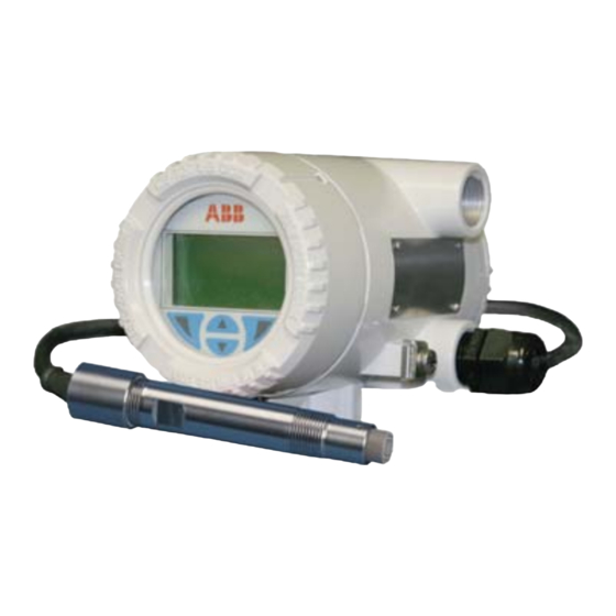
Endura ACA592
4-electrode conductivity transmitter
Introduction
—
Rugged design
transmitter for
industrial applications
Endura ACA592 4-electrode transmitters are
suitable for wide-range conductivity applications
and slurries.
The ACA592 transmitter is fully compatible with
ABB's comprehensive range of 4-electrode
conductivity sensors and enables users to measure
conductivity in applications from clean water to
harsh chemicals.
The ACA592 has automatic temperature sensor
recognition for both 2- and 3-wire RTD inputs from
common inputs such as Pt100, Pt1000 and 3k
Balco.
Measurement made easy
ACA592 transmitters are communication-ready
field devices with microprocessor-controlled
electronics. For bi-directional communication, an
FSK signal is superimposed on the 4 to 20 mA
output signal via the HART protocol.
The device type manager (DTM) can be used to
configure, poll and test devices on a PC. Handheld
terminals such as the DHH801 also support
communication.
The transmitter is equipped with an LCD display
used to show the current process data. The 4 keys
beneath the transmitter enable local configuration.
Advertisement
Table of Contents

Related Manuals for ABB Endura ACA592


Summary of Contents for ABB Endura ACA592
- Page 1 Measurement made easy Introduction — Rugged design transmitter for industrial applications Endura ACA592 4-electrode transmitters are ACA592 transmitters are communication-ready suitable for wide-range conductivity applications field devices with microprocessor-controlled and slurries. electronics. For bi-directional communication, an FSK signal is superimposed on the 4 to 20 mA The ACA592 transmitter is fully compatible with output signal via the HART protocol.
- Page 2 For more information Further publications for the Endura ACA592 4-electrode transmitter are available for free download from: www.abb.com/analytical See links and reference numbers below or scan this code: Description Search for or click on Data Sheet Endura ACA592 DS/ACA592-EN Conductivity transmitter...
-
Page 3: Table Of Contents
Endura ACA592 4-electrode conductivity transmitter Contents Contents Safety ............................... 4 Technical Limits ........................4 Operator Liability ........................4 1.2.1 Operating Safety Information ..................4 1.2.2 Special Conditions of Use (FM Approval) ............... 4 Health & Safety ........................5 Electrical Safety – IEC / EN 61010-1 ..................5 1.4.1 Electrical Installation Safety Information ................. - Page 4 Endura ACA592 4-electrode conductivity transmitter Contents Electrical Installation ........................26 Cable Glands and Plugs ......................26 4.1.1 ACA592–XX for Intrinsically Safe, Type n and Non-incendive Installations ....26 4.1.2 ACA592–XX Ex d Models without Cable Gland ............26 DC Power Supply Connections ....................28 Sensor Connections .......................
- Page 5 Endura ACA592 4-electrode conductivity transmitter Contents HART Communication ........................73 HART Device Type Codes ..................... 73 HART Configuration Map ....................... 74 HART Universal Commands ....................76 HART Common Practice Commands ..................78 10 Specification ..........................80 11 Spares and Accessories ........................ 84 Appendix A Permits and Certification ....................
-
Page 6: Safety
1.2 Operator Liability When measuring corrosive and abrasive materials, the operator must examine the resistance of all parts that come into contact with the process being measured. ABB will assist with the selection but cannot, however, accept any liability. Operators must strictly observe the national regulations applicable in their countries with regards to installation, functional tests, repairs and maintenance of electrical devices. -
Page 7: Health & Safety
Endura ACA592 4-electrode conductivity transmitter 1 Safety 1.3 Health & Safety Health and Safety To ensure that our products are safe and without risk to health, the following points must be noted: The relevant sections of these instructions must be read carefully before proceeding. -
Page 8: Symbols - En / Iec 61010-1
Endura ACA592 4-electrode conductivity transmitter 1 Safety 1.5 Symbols – EN / IEC 61010-1 One or more of the following symbols may appear on the equipment labelling: Protective earth (ground) terminal. Functional earth (ground) terminal. Direct current supply only. Alternating current supply only. -
Page 9: Product Recycling Information
Endura ACA592 4-electrode conductivity transmitter 1 Safety This symbol indicates the need for protective hand wear. Electrical equipment marked with this symbol may not be disposed of in European public disposal systems. In conformity with European local and national regulations, European electrical equipment users must now return old or end-of-life equipment to the manufacturer for disposal at no charge to the user. -
Page 10: Product Disposal
2002/96/EC. Proper disposal prevents negative effects on people and the environment, and supports the reuse of valuable raw materials. If it is not possible to dispose of old equipment correctly, ABB Service will accept and dispose of returns for a fee. -
Page 11: Returning Transmitters
Use the original packaging or suitably secure packaging for returning the transmitter for repair or recalibration. Contact the local ABB office or sales representative for return authorization number and address. All transmitters returned for service or repair to ABB must be free from any hazardous materials (acids, alkali, solvents, etc.). 1.8.1 Transport Safety Information Observe the following information: ... -
Page 12: Safety Conventions
Other than the serviceable items listed in Section 11, page 84, none of the transmitter's components can be serviced by the user. Only personnel from ABB or its approved representative(s) is (are) authorized to attempt repairs to the system and only components formally approved by the manufacturer should be used. -
Page 13: Use In Areas Requiring Ignition Protection
Endura ACA592 4-electrode conductivity transmitter 2 Use in Areas Requiring Ignition Protection 2 Use in Areas Requiring Ignition Protection Special regulations must be observed in explosion-protection zones for the auxiliary power connection, signal inputs/outputs and ground connection. Caution. All parts must be installed in accordance with manufacturer information and relevant standards and regulations. -
Page 14: Hazardous Area Relevant Information
Endura ACA592 4-electrode conductivity transmitter 2 Use in Areas Requiring Ignition Protection 2.5 Hazardous Area Relevant Information Note. The explosion-proof or ignition-proof designation is displayed on the agency certification label. 2.5.1 ACA592-XX.A1… (Intrinsic Safety) ATEX/IECEx approved for use in zone 0/20. -
Page 15: Aca592-Xx.a2
Housing design: II 3 D Ex tD A22 IP66 T135 ºC, –20 ºC T 60ºC Note. Both type n and dust ratings are combined when ACA592-XX.A3… is ordered. ABB statement of conformity in accordance with ATEX directive. OI/ACA592/EC–EN Rev. B... -
Page 16: Aca592-Xx.f1 Or .C1 (Intrinsic Safety)
Endura ACA592 4-electrode conductivity transmitter 2 Use in Areas Requiring Ignition Protection 2.5.4 ACA592-XX.F1 or .C1 (Intrinsic Safety) Note. See installation drawings P0908 – FM (page 87), or P0910 – CSA (page 89) for allowable sensors. Agency Area Classification Class I, Div. 1, Groups A, B, C, D Class II/III, Div. -
Page 17: Aca592-Xx.f2 Or .C2 (Explosion-Proof)
Endura ACA592 4-electrode conductivity transmitter 2 Use in Areas Requiring Ignition Protection 2.5.5 ACA592-XX.F2 or .C2 (Explosion-proof) Agency Area Classification XP, Class I, Div. 1, Groups A, B, C, D Class II/III, Div. 1, Group F, G; T4 Ta = 60 ºC Class I, Div. - Page 18 Endura ACA592 4-electrode conductivity transmitter 2 Use in Areas Requiring Ignition Protection Output Parameters Open-circuit voltage (maximum) = 11.8 V Short-circuit current (maximum) = 5 mA Maximum output power = 15 mW Allowed inductance (total) = 1 H Allowed capacitance (total) = 1.45 µF...
-
Page 19: Mechanical Installation
Endura ACA592 4-electrode conductivity transmitter 3 Mechanical Installation 3 Mechanical Installation 3.1 Hazardous Area Installation For hazardous area designation, the Ex installation is described on a separate 'HazLoc' label mounted on the transmitter body – see Section 3.4.5, page 23. -
Page 20: Installation Conditions
Endura ACA592 4-electrode conductivity transmitter 3 Mechanical Installation 3.3 Installation Conditions Ensure the following installation conditions are met: 1. Install the transmitter with consideration to ambient conditions. 2. Locate the transmitter in a position where the temperature and humidity specifications are not exceeded and ensure the transmitter is protected from direct sunlight, rain, snow and hail. -
Page 21: Dimensions
Endura ACA592 4-electrode conductivity transmitter 3 Mechanical Installation 3.4 Dimensions 3.4.1 Transmitter-only Dimensions (Excluding Mounting Bracket) Dimensions in mm (in.) 46.5 (5.91) (1.83) 60.5 (2.38) (3.58) (4.15) 29.4 (1.16) 46.5 Transmitter (1.83) Label – 'HazLoc' Label – in. NPT or M20 see Fig. -
Page 22: Wall-Mount Transmitter Dimensions
Endura ACA592 4-electrode conductivity transmitter 3 Mechanical Installation 3.4.2 Wall-mount Transmitter Dimensions Warning. Install the wall-mounting bracket on a sufficiently stable wall. Dimensions in mm (in) (6.85) (6.85) (8.32) (9.42) Fig. 3.4 Wall Installation Wall-mounting an ACA592–XX transmitter Referring to Fig. 3.4: 1. -
Page 23: Pipe-Mount Transmitter Dimensions
Endura ACA592 4-electrode conductivity transmitter 3 Mechanical Installation 3.4.3 Pipe-mount Transmitter Dimensions Dimensions in mm (in.) (5.45) (7.00) (9.08) Fig. 3.5 Pipe Installation Pipe-mounting an ACA592–XX transmitter Referring to Fig. 3.5: 1. Select a suitable pipe (maximum 50 mm [2 in.]) as close as possible to the sensor. -
Page 24: Transmitter Label
Endura ACA592 4-electrode conductivity transmitter 3 Mechanical Installation 3.4.4 Transmitter Label ACA592-ECxXXxXXxXxXx ACA592EC\1A\30 CA592/EC-EN Key: Model number Transmitter communication type Permissible power supply Product documentation (manual) Manufacturing location Product serial number Permissible ambient temperature operating range CE Mark (EC conformity) Fig. -
Page 25: Hazloc' Labels
Endura ACA592 4-electrode conductivity transmitter 3 Mechanical Installation 3.4.5 'HazLoc' Labels ATEX (Zone 0, Zone 1, Zone 2) Label 0344 Fig. 3.7 Example of ATEX (Zone 0, Zone 1, Zone 2) 'HazLoc' Label CSA / FM (Classes I, II, III; Div. 1 Intrinsic Safety and Div. 2 Non-incendive) Label Fig. - Page 26 Endura ACA592 4-electrode conductivity transmitter 3 Mechanical Installation CSA / FM (Classes I, II and III; Div. 1 explosion- and ignition-proof) Label ® Fig. 3.9 Example of CSA / FM (Classes I, II and III; Div. 1 explosion- and ignition-proof) 'HazLoc' Label...
-
Page 27: Aligning The Cartridge Lcd Display
Endura ACA592 4-electrode conductivity transmitter 3 Mechanical Installation 3.4.6 Aligning the Cartridge LCD Display Warning. Isolate the transmitter from power supplies before aligning the cartridge LCD display. Because the transmitter's mounting bracket enables the transmitter housing to be positioned in 90 ° steps only between 0 and 360 °, it may be necessary to re-position the cartridge to ensure the cartridge LCD... -
Page 28: Electrical Installation
Endura ACA592 4-electrode conductivity transmitter 4 Electrical Installation 4 Electrical Installation Warning. Observe all local instructions and regulations governing electrical installation. Ensure the power supply and / or bus connections are switched off before making connections. Use a maximum of 12 SWG (10 AWG) wire for connection of this transmitter. - Page 29 Endura ACA592 4-electrode conductivity transmitter 4 Electrical Installation 18.3 14.5 (0.72) (0.57) 36.1 38.6 (1.42) (1.52) 14.2 20.3 (0.56) (0.80) 43.2 55.4 (1.70) (2.18) Fig. 4.1 Cable Glands and Plugs Item Description in. NPT nylon cable gland in. NPT nylon conduit plug...
-
Page 30: Dc Power Supply Connections
Endura ACA592 4-electrode conductivity transmitter 4 Electrical Installation 4.2 DC Power Supply Connections Connection Label* (inside End Cap) Transmitter Type Key: *DC Power Supply Requirements: Non-Intrinsically safe transmitters: Positive + 12 to 42 V DC, 4 to 20 mA Negative –... -
Page 31: Sensor Connections
Endura ACA592 4-electrode conductivity transmitter 4 Electrical Installation 4.3 Sensor Connections Caution. The connection terminals accept cables up to a maximum peripheral wire cross section of 2.5 mm (12 SWG [10 AWG]). Do not use a rigid conductor material as this can result in wire breaks. -
Page 32: Aca592 4-Electrode Conductivity Transmitter - Sensor Connections
Endura ACA592 4-electrode conductivity transmitter 4 Electrical Installation 4.3.1 ACA592 4-Electrode Conductivity Transmitter – Sensor Connections To connect the sensor: 1. Refer to Table 4.2 to identify the correct cable wires for the ACA592–EC 4-electrode conductivity transmitter. 2. Route the sensor wiring through one of the three threaded connections in the transmitter housing and use an appropriate gland (refer to Fig. -
Page 33: Integral Sensor Cable Connection
Endura ACA592 4-electrode conductivity transmitter 4 Electrical Installation 4.4 Integral Sensor Cable Connection For installations where the sensor is close to the transmitter, use an integral c cable. This design is preferred for submersible installations as there is no connector that could be affected by moisture. -
Page 34: Power Supply Requirements
Endura ACA592 4-electrode conductivity transmitter 4 Electrical Installation 4.6 Power Supply Requirements Warning. The connection terminals accept cables with a maximum peripheral wire cross-section of 2.5 mm 12 SWG (10 AWG). Switch off the power supply before connecting the transmitter. -
Page 35: Standard Application With Hart Functionality
Endura ACA592 4-electrode conductivity transmitter 4 Electrical Installation 4.6.2 Standard Application with HART Functionality Adding resistance R increases the minimum supply voltage: U + 0.022A x (R Smin Mmin Where: – Minimum operating voltage of transmitter Mmin (refer to technical data for transmitter) –... -
Page 36: Electrical Connection In Hazardous Area
Endura ACA592 4-electrode conductivity transmitter 4 Electrical Installation 4.6.3 Electrical Connection in Hazardous Area Special interconnections are required for use in hazardous areas depending on the safety requirements. Caution. Refer to Section 2, page 11 and Section 10, page 80 for explosion risk area requirements. -
Page 37: Installation In Hazardous Areas
Endura ACA592 4-electrode conductivity transmitter 4 Electrical Installation 4.6.4 Installation in Hazardous Areas ACA592–XX transmitters can be installed in a wide variety of industrial sectors. Systems that require ignition protection are divided into zones. As a result, different instruments are also required. - Page 38 Endura ACA592 4-electrode conductivity transmitter 4 Electrical Installation Type n (Non-sparking) – ATEX/IEC Ex II 3 G Ex nA IIC; T4 60 ºC II 3 D Ex tD A22 IP66 T135 ºC, –20 ºCT Hazardous Area Hazardous Area Safety Area...
- Page 39 Endura ACA592 4-electrode conductivity transmitter 4 Electrical Installation Non-Incendive (using Div. 2 field wiring) – FM and CSA Note. Local regulations for the power supply must be observed and approved wiring methods for Div. 2 hazardous classified locations must be used.
- Page 40 Endura ACA592 4-electrode conductivity transmitter 4 Electrical Installation Explosion-proof, Dust-Ignition-proof – FM and CSA Note. Local regulations governing the installation of the power supply and the sensor must be observed. Do not open the cover when circuits are live. XP, Class I, Div. 1, Groups A, B, C, D Class I, Div.
-
Page 41: Start-Up And Operation
Endura ACA592 4-electrode conductivity transmitter 5 Start-up and Operation 5 Start-up and Operation 5.1 Navigating Menus and Parameters The four keys below the display are used to navigate menus and to execute all system commands and selections. Menu Easy Setup... -
Page 42: Security Levels And Password Access
Endura ACA592 4-electrode conductivity transmitter 5 Start-up and Operation 5.2 Security Levels and Password Access At power-up, the Start-up Display and process display (Operator Page) screens are activated in sequence. Note. Passwords at Standard / Advanced level are disabled by default. They can be enabled and disabled independently by end-users via the Service level. -
Page 43: Security Permissions
Endura ACA592 4-electrode conductivity transmitter 5 Start-up and Operation 5.2.1 Security Permissions Table 5.1 (below) provides an overview of the permissions enabled at each access level: Access Level Read / Write Read-only Read-only None All levels and sub-levels ... -
Page 44: Configuration Menus Overview
Endura ACA592 4-electrode conductivity transmitter 5 Start-up and Operation 5.3 Configuration Menus Overview Note. Parameters displayed are dependent on the option selected at the Analyzer Type parameter. The following measurement-specific parameters are available: 4-Electrode / Conductivity – see Section 7.2.1, page 50 ... - Page 45 Used to configure the transmitter's HART communication support. Exit Select Service Menu Service Note Service level parameters are reserved for ABB factory-trained personnel – contact the Company for support. Select Exit Table 5.2 Operating Menus Overview (Continued) OI/ACA592/EC–EN Rev. B...
-
Page 46: Configuration
Configuration can be performed with any FDT network applications that are approved for use with the DTM (for example, ABB AssetVision Basic / Professional). The bus can be connected via FSK modem as well as HART + USB or HART Multiplexer. -
Page 47: Configuration Dip Switch
Endura ACA592 4-electrode conductivity transmitter 6 Configuration 6.2 Configuration DIP Switch Warning. Isolate the transmitter from power supplies before accessing / setting the DIP switch. A 6-pin DIP switch located behind the transmitter cartridge is used to enable / protect configuration settings (see Fig. -
Page 48: Operator Pages And Menus
Endura ACA592 4-electrode conductivity transmitter 7 Operator Pages and Menus 7 Operator Pages and Menus 7.1 Process Display At power-up (if startup is successful) the startup screen is displayed momentarily after approximately 3 seconds. The display is then blank for the next 6 seconds (while the transmitter performs a self-check). -
Page 49: Operator
Endura ACA592 4-electrode conductivity transmitter 7 Operator Pages and Menus 7.1.1 Operator Pages The Operator Pages are accessed from the Operator Menu by Operator Menu using the to scroll to the required page and Diagnostics pressing the key. Operator Page 1 Operator Page 2 Four Operator pages are available to monitor operation. - Page 50 Endura ACA592 4-electrode conductivity transmitter 7 Operator Pages and Menus Display Example Title and Function Diagnostics Configuration –– S010.047 –– Diagnostic screen – used to display active diagnostic system data Temp Comp in (NAMUR icon, diagnostic code and diagnostic message).
- Page 51 Endura ACA592 4-electrode conductivity transmitter 7 Operator Pages and Menus Display Example Title and Function Operator Page 4 ACA592XX X.XX Primary value (plus associated unit) on the first line, a temperature 77.0 °F value (plus associated unit) on the second line and the calculated XX.X...
-
Page 52: Parameter Maps
Endura ACA592 4-electrode conductivity transmitter 7 Operator Pages and Menus 7.2 Parameter Maps 7.2.1 ACA592 4-Electrode Conductivity Transmitter – Conductivity Parameter Map Refer to Section 7.3.2, page 53 Refer to Section 7.3.1, page 52 Refer to Section 7.3.3, page 55... -
Page 53: Aca592 4-Electrode Conductivity Transmitter - Concentration Parameter Map
Endura ACA592 4-electrode conductivity transmitter 7 Operator Pages and Menus 7.2.2 ACA592 4-Electrode Conductivity Transmitter – Concentration Parameter Map Refer to Section 7.3.2, page 53 Refer to Section 7.3.1, page 52 Refer to Section 7.3.3, page 55 Menu Menu Menu... -
Page 54: Aca592 4-Electrode Conductivity Transmitter Parameters
Endura ACA592 4-electrode conductivity transmitter 7 Operator Pages and Menus 7.3 ACA592 4-Electrode Conductivity Transmitter Parameters 7.3.1 Easy Setup Users with Advanced level access have read and write Menu Easy Setup privileges to the parameters listed. Users with Standard and Read Only access have read-only privileges to parameters at Easy Setup level. -
Page 55: Calibrate
Endura ACA592 4-electrode conductivity transmitter 7 Operator Pages and Menus 7.3.2 Calibrate Used to calibrate the sensor and transmitter. Menu Calibrate Select Exit Calibrate Level Parameter Description Conductivity Cal Enabled if analyzer type = Conductivity. The 4-electrode mode may require wet calibration for the greatest accuracy. - Page 56 Endura ACA592 4-electrode conductivity transmitter 7 Operator Pages and Menus Temperature Calibration Step Procedure Screen At the Temperature Cal parameter, wait for the message 'Continue When Stable' to be displayed then press the key to continue. Enter the new temperature using the...
-
Page 57: Device Setup
Endura ACA592 4-electrode conductivity transmitter 7 Operator Pages and Menus 7.3.3 Device Setup Used to set the sensor / sensor input, run temperature sensor Menu / sensor recognition and obtain transmitter information. Device Setup Note. Required level of access = Advanced. - Page 58 Endura ACA592 4-electrode conductivity transmitter 7 Operator Pages and Menus Device Setup Level Parameter Description Temp. Sensor Temperature sensor parameters. Temp. unit Sets the temperature unit (°C or °F) applied to all transmitter temperature parameters and values. Temp. Comp. Type Temperature compensation type.
- Page 59 Endura ACA592 4-electrode conductivity transmitter 7 Operator Pages and Menus Device Setup Level Parameter Description Temp. Sensor Type Indicates the type of temperature sensor detected. Options comprise: Pt100 Pt1000 Balco 3k Run TC Recognition Starts the auto recognition process for the sensor.
-
Page 60: Input/Output
Endura ACA592 4-electrode conductivity transmitter 7 Operator Pages and Menus 7.3.4 Input/Output Used to setup process value high / low ranges, damping and Menu alarm current settings. Input/Output Select Exit Input Output Level Parameter Description PV Rng Units Enables conductivity units selection for the purpose of editing the PV range values (PV Lo / Hi Rng Val). -
Page 61: Display
Endura ACA592 4-electrode conductivity transmitter 7 Operator Pages and Menus 7.3.5 Display Used to configure and format the information displayed, Menu including: language, data displayed on Operator Pages 3 and Display 4 and screen contrast. Select Exit Display Level Parameter... -
Page 62: Diagnostics
Endura ACA592 4-electrode conductivity transmitter 7 Operator Pages and Menus 7.3.6 Diagnostics Used to perform a loop test (output verification) and indicate Menu the diagnostic status (actual / simulated). Diagnostics Select Exit Diagnostics Level Parameter Description Loop Test The current output of the transmitter can be adjusted between 3.8 and 21.5 mA. -
Page 63: Communication
Endura ACA592 4-electrode conductivity transmitter 7 Operator Pages and Menus 7.3.7 Communication Used to configure HART communication parameters – see Menu Section 9, page 73. Communication Select Exit Communication Level Parameter Description Poll Addr The Poll Addr. (poll address) is used by a HART communication master to communicate with a HART device. -
Page 64: Service
Endura ACA592 4-electrode conductivity transmitter 7 Operator Pages and Menus 7.3.8 Service Service level parameters are read-only and reserved for ABB Menu factory-trained personnel. Service Exit Select Service Level Parameter Description Standard access Enables / disables password protection to the Standard Access level. -
Page 65: Troubleshooting And Diagnostics
Endura ACA592 4-electrode conductivity transmitter 8 Troubleshooting and Diagnostics 8 Troubleshooting and Diagnostics During operation, the transmitter performs continuous diagnostic checks on hardware, software and sensor functions. If a non-conformance condition is detected the an alert is displayed in the lower portion of the Operator screen. -
Page 66: Diagnostic Messages
Endura ACA592 4-electrode conductivity transmitter 8 Troubleshooting and Diagnostics 8.1 Diagnostic Messages Diagnostic messages are related to 5 conditions: 1. Process diagnostics – the process setup or sensor connected to the ACA592 transmitter. 2. Sensor diagnostics – the sensor, its connections or calibration. - Page 67 Endura ACA592 4-electrode conductivity transmitter 8 Troubleshooting and Diagnostics Diagnostic Message Possible Cause(s) Corrective Action [Sub-error Message] [Related Condition] F086.000 PV related sensor board electronics Contact factory. malfunction. PV input error [ELECTRONICS] F088.016 Data exchange with sensor Power cycle the device and check if the problem is electronics board has failed.
- Page 68 Endura ACA592 4-electrode conductivity transmitter 8 Troubleshooting and Diagnostics Diagnostic Message Possible Cause(s) Corrective Action [Sub-error Message] [Related Condition] F116.023 Electronic memory corrupted. Replace electronics. Memory Failure [ELECTRONICS] Contact factory. M023.036 Sensor electronics related Check sensor wiring. malfunction. Sensor electronics If problem persists, contact factory.
- Page 69 Endura ACA592 4-electrode conductivity transmitter 8 Troubleshooting and Diagnostics Diagnostic Message Possible Cause(s) Corrective Action [Sub-error Message] [Related Condition] M084.038 Ground loops present or shorted Verify sensor wiring. sensor cable. Ground loops present or Verify sensor wiring is not shorted to other wiring or...
- Page 70 Endura ACA592 4-electrode conductivity transmitter 8 Troubleshooting and Diagnostics Diagnostic Message Possible Cause(s) Corrective Action [Sub-error Message] [Related Condition] S072.040 Sensor temperature is above range. Verify sensor wiring. Snsr temperature [PROCESS] Verify configuration related to temperature sensor over range and temperature compensation.
-
Page 71: Diagnosis Screens
Endura ACA592 4-electrode conductivity transmitter 8 Troubleshooting and Diagnostics 8.2 Diagnosis Screens Diagnosis screens can be viewed using the DTM or the EDD graphical user interface (they cannot be viewed on the transmitter's display). 8.2.1 ACA592 4-Electrode Conductivity Transmitter – Diagnosis Overview Screen An overview of active / inactive diagnostic conditions can be viewed on the diagnosis Overview screen –... -
Page 72: Aca592 4-Electrode Conductivity Transmitter - Diagnosis Masking
Endura ACA592 4-electrode conductivity transmitter 8 Troubleshooting and Diagnostics 8.2.2 ACA592 4-Electrode Conductivity Transmitter – Diagnosis Masking Certain non-critical diagnoses can be masked using the DTM or the EDD. This feature is not accessible via the transmitter's display and a masked diagnosis is not reported when it occurs. The list of maskable diagnoses is available on the DTM and EDD graphical user interface only. -
Page 73: Aca592 4-Electrode Conductivity Transmitter - Diagnosis Simulation
Endura ACA592 4-electrode conductivity transmitter 8 Troubleshooting and Diagnostics 8.2.3 ACA592 4-Electrode Conductivity Transmitter – Diagnosis Simulation All diagnosis conditions except Loop test (see page 64) can be simulated individually using the DTM or EDD. To simulate a diagnosis, turn diagnosis simulation ON, select a diagnosis and send it to the transmitter. In Simulated Diagnosis mode, all active diagnoses are suppressed and only the simulated diagnosis is reported. - Page 74 Endura ACA592 4-electrode conductivity transmitter 8 Troubleshooting and Diagnostics The diagnosis Simulation screen is shown in Fig. 8.4. Fig. 8.4 ACA592 4-Electrode Conductivity Transmitter – Diagnosis Simulation Screen OI/ACA592/EC–EN Rev. B...
-
Page 75: Hart Communication
Endura ACA592 4-electrode conductivity transmitter 9 HART Communication 9 HART Communication For ease of identification, each HART device features a configurable 8-character HART tag. In addition to the HART tag, each device has a HART address (set to the default value 0). At this address the device operates in HART standard communication mode (point-to-point operation). -
Page 76: Hart Configuration Map
Endura ACA592 4-electrode conductivity transmitter 9 HART Communication 9.2 HART Configuration Map Manufacturer Device Type Device ID Device Serial No. Device revision HART revision Poll Address Write protect Hardware revision Installation Date Software revision HART Tag Device Final Assembly Number... - Page 77 Endura ACA592 4-electrode conductivity transmitter 9 HART Communication ... Continued from Fig. 9.1, page 74 Primary Value Temperature (SV) Operate Process Values Uncomp. Conductivity (TV) Comp. Conductivity (QV) Current Out Conductivity/Concentration Start Cond/Conc. Cal PV Slope Temperature Cal Start Tempurature Cal...
-
Page 78: Hart Universal Commands
Endura ACA592 4-electrode conductivity transmitter 9 HART Communication 9.3 HART Universal Commands Command Description Details Expanded device type code. Manufacturer identification code. Manufacturer device type code. Number of preambles. Read Transmitter Unique Revision level of HART Universal Command set implemented. - Page 79 Endura ACA592 4-electrode conductivity transmitter 9 HART Communication Command Description Details When set to 0 Current Output is active and provides an analog output proportional to the Primary Value. Write Polling Address HART operates in point-to-point mode. When set between 1 to 15, Current Output is fixed at 4 mA and HART operates in multi-drop mode.
-
Page 80: Hart Common Practice Commands
Endura ACA592 4-electrode conductivity transmitter 9 HART Communication 9.4 HART Common Practice Commands Command Description Details Write Damping Enables the user to alter the PV damping value in seconds Enables the low and high range values to be set for the Write the PV Range range. - Page 81 Endura ACA592 4-electrode conductivity transmitter 9 HART Communication Command Description Details The status of the device, determined from results of the continuous self-diagnostics, is reported every time communications with the device are established. Read Device Status If the device indicates there is additional status information, it can be obtained via this command.
-
Page 82: Specification
Endura ACA592 4-electrode conductivity transmitter 10 Specification 10 Specification Input Sensor Types ACA592–EC ABB 4-electrode sensors Measurement Range and Resolution ACA592 4-electrode conductivity transmitter: Sensor Group Measurement Range Resolution / Accuracy / Linearity / Stability Group A 0 to 2000 mS/cm 0.1 µS/cm... - Page 83 Endura ACA592 4-electrode conductivity transmitter 10 Specification Output Signal Configurable 4 to 20 mA (standard with HART) User-programmable linear and non-linear across the entire range Dynamic range 3.9 to 20.75 mA (3.8 mA = low alarm level, 21.5 mA = high alarm level)
- Page 84 Endura ACA592 4-electrode conductivity transmitter 10 Specification General Information Display Update Speed < 250 milliseconds Environmental (Temperature) Operating: –20 to 60 °C (–4 to 140 °F) Storage: –40 to 80 °C (–40 to 176 °F) Humidity < 95 % RH non-condensing...
- Page 85 Endura ACA592 4-electrode conductivity transmitter 10 Specification Equipment Markings Intrinsic Safety – FM and CSA Class I, Div. 1, Groups A, B, C, D Class II/III, Div. 1, Group E, F, G; T4 Ta = 60 ºC Class I, Div. 1, Groups A, B, C, D Class II, Div.
-
Page 86: Spares And Accessories
Endura ACA592 4-electrode conductivity transmitter 11 Spares and Accessories 11 Spares and Accessories Part Number Description Item 4TB9515-0281 LCD display 4TB9515-0282 Window cover 4TB9515-0283 Wall / pipe mounting kit in. NPT nylon cable gland 4TB9515-0285 (I.S./Non-Incendive in. NPT nylon conduit plug 4TB9515-0286 (I.S./Non-Incendive... - Page 87 Endura ACA592 4-electrode conductivity transmitter 11 Spares and Accessories Part Number Description Item in. NPT 316 stainless steel Ex d 4TB9515-0290 (Explosion-proof) conduit plug M20 316 stainless steel Ex d 4TB9515-0291 (Explosion-proof) cable gland M20 316 stainless steel Ex d...
-
Page 88: Appendix A Permits And Certification
– EMC directive 2004/108/EC, Low Voltage directive 2006/95/EC, ATEX directive 94/9/EC For ignition-protection applications: – Conforms with hazardous area directive 94/9/EC By placing the CE mark on its devices, ABB declares its conformance with these directives. Table A.1 Permits and Certification OI/ACA592/EC–EN Rev. B... -
Page 89: Appendix B Installation Drawings
Endura ACA592 4-electrode conductivity transmitter Appendix B Installation Drawings Appendix B Installation Drawings B.1 Drawing P0908 Fig. B.1 Installation Drawing P0908 OI/ACA592/EC–EN Rev. B... -
Page 90: Drawing P0909
Endura ACA592 4-electrode conductivity transmitter Appendix B Installation Drawings B.2 Drawing P0909 Fig. B.2 Installation Drawing P0909 OI/ACA592/EC–EN Rev. B... -
Page 91: Drawing P0910
Endura ACA592 4-electrode conductivity transmitter Appendix B Installation Drawings B.3 Drawing P0910 Fig. B.3 Installation Drawing P0910 OI/ACA592/EC–EN Rev. B... -
Page 92: Drawing P0911
Endura ACA592 4-electrode conductivity transmitter Appendix B Installation Drawings B.4 Drawing P0911 Fig. B.4 Installation Drawing P0911 OI/ACA592/EC–EN Rev. B... - Page 93 Acknowledgements • HART is a registered trademark of the HART Communication Foundation. • Siemens is a copyright of Siemens AG. Sales Service Software...
- Page 94 We reserve the right to make technical changes or modify the contents of this document without prior notice. With regard to purchase orders, the agreed particulars shall prevail. ABB does not accept any responsibility whatsoever for potential errors or possible lack of information in this document.