
Related Manuals for ROLEC SecuriCharge ROLEC0111B


Summary of Contents for ROLEC SecuriCharge ROLEC0111B
- Page 1 INSTALLATION & OPERATION MANUAL SECURICHARGE Manufactured Intelligent EV charging unit in the UK...
-
Page 2: Product Support
Date Published: December 2022 Rolec Services Ltd are the publishers of this document and own the rights to use the text, images and all technical content contained within. Content supplied by third parties / partner organisations remains the property of that organisation and is used by agreement with the supplier. -
Page 3: Table Of Contents
Product Support Contents Product Support Safety Safety Advice within this Manual Product Overview Product Features About ‘Smart’ Services About Load Balancing About Load Management About Demand Side Response About PEN Protection Security – Tamper Protection Product Specification Unpacking Standard Contents Options and Accessories Labelling Installation... -
Page 4: Safety
Rolec Services Ltd cannot accept any responsibility for improper installation or any problems arising from improper installation. NOTE: Damage to the equipment, connected systems or to property caused by improper installation are the responsibility of the installer. -
Page 5: Product Overview
Users may need to consider an external antenna and/or booster to their Wi-Fi system to reach remote chargepoints. VendElectric is Rolec EV’s chargepoint management platform. Other preferred partners are: Monta, Fuuse, and ChargePlace Scotland, but others include Parkable and Ampeco. -
Page 6: About 'Smart' Services
Product Overview NOTE: The United Kingdom has introduced new regulations (SI 2021/1467) that apply to domestic and private EV chargepoints, and which aligns them with other ‘Smart’ appliances. The new regulations are, amongst other things, designed to balance demands for power and to deliver an efficient use of power across the country whilst maintaining a consistent and secure service to EV drivers, when and where they need it. -
Page 7: About Load Balancing
Rolec chargepoints are pre-configured to load balance with a 13A ‘buffer’. This means that whatever the property fuse may be, load balancing will start 13A before its maximum limit is reached. -
Page 8: About Load Management
NOTE: Where a Rolec Load Balancing Current Transformer (CT) has been installed and connected to a load balancing enabled Rolec chargepoint, it will reduce the supply of power to the vehicle where the combined demand of the property and vehicle would exceed the power available to the property as a whole. -
Page 9: About Pen Protection
Product Overview About PEN Protection The TruePEN system removes the need to install a dedicated earth for the chargepoint. In the event of a fault, the system will break all power cable connections between the chargepoint and the vehicle. A PEN fault is most commonly seen as either, an undervoltage or an overvoltage entering the chargepoint from the mains supply. -
Page 10: Product Specification
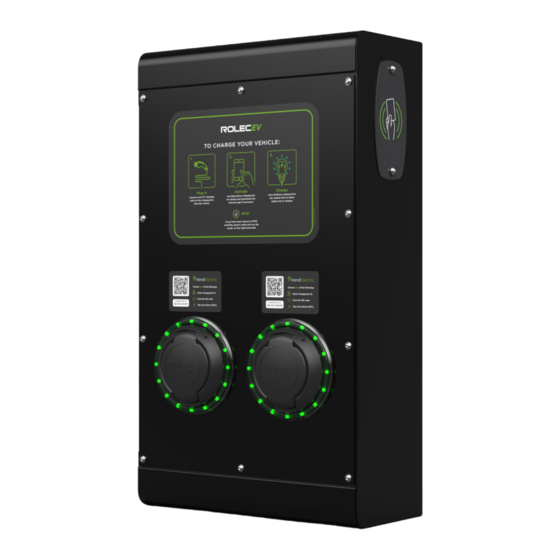
Product Specification Product Specification User Instructions External Antenna QR Code Socket ID Label RFID Sensor LED ‘Halo’ (on side) Status Indicator Charging Socket External RFID Antenna Sensor (on side) QR Code Socket ID Labels Charging Sockets Access Panel Figure 1 General Arrangement and Dimensions (Single and Double Socket Models) SecuriCharge Intelligent EV Charging Unit EVSM-V01-R1 Installation and Operation Manual Page 9 of 33... - Page 11 Product Specification EV Charge Controller for RFID Sensor socket 1(Front Layer) socket 2 (Rear Layer) RCBO (Socket 2) Smart Communications Module (Right-hand Side Panel) MID Meter (Socket 2) Socket 1 MID Meter (Socket 1) RCBO (Socket 1) Incoming Power Terminals (Single phase version shown) Figure 2 Internal Components - Typical Locations EVSM-V01-R1 Installation and Operation Manual...
- Page 12 Product Specification Smart Link Connection Meter Connector 2x CT Connectors Status Indicator Power ‘IN’ ‘Halo’ Connector Connector to Power ‘OUT’ and N, E, L. Signal Connector to Socket or Cable L, N, E. Figure 3 EV Charge Controller GPRS Antenna Connection Connection to RFID Board...
- Page 13 Product Specification Connection Charging Input Unit Product Type Output Supply Colour Code 1x 32A Black ROLEC0111B 1x Type 2 (IEC 62196) Up to 7.4kW (32A) Single Phase Grey ROLEC0111G charging socket per socket 230V AC (±10 %) Single 50/60Hz White ROLEC0111W Phase Units...
- Page 14 Certification Markings – CE & UKCA Warranty 3 years Rolec Services Ltd are a registered manufacturer (WEE/AG3499TY) within the WEEE Recycling Scheme, allowing its products at the end of their life, to be processed by an appropriate local service provider.
-
Page 15: Unpacking
Standard Contents EV chargepoint Rolec ‘EV Connect’ Configuration Tag Rolec VendElectric QR Code Socket ID Label Fixing Kit (Qty 4, 4 x 50mm screws a plugs) Installation and Operation Manual 1. Examine the package and make sure the contents have not been damaged in transit. -
Page 16: Labelling
Labelling Labelling Observe any/all labels displayed on the equipment or inside the enclosure. Figure 5 Typical Product Rating and Serial Number Label Figure 7 Socket ID Label Figure 6 Configuration Tag (Back and Front) Figure 8 Instructions and RFID Label Figure 9 Typical Socket Type and power Rating Labels NOTES:... -
Page 17: Installation
Units using mobile networks require a suitable signal of 14 CSQ or better. Units using Wi-Fi connectivity require a strong, stable connection. Rolec cannot be held responsible or accountable in the event that a unit using a mobile network or Wi-Fi is installed in a location without adequate network signal. - Page 18 Installation 3. Determine where power and other cables (CT and Ethernet – if required) will enter the chargepoint enclosure. Discuss cable routing and cable entry into the enclosure with the end user. Plan the installation accordingly. Depending on the model of chargepoint, cables may enter through the bottom or back of the enclosure.
-
Page 19: Schematics
Installation Schematics INCOMING SUPPLY ACEQ0185 I ON 230V 50Hz O OFF I n 0.03A 10000 IEC/EN 61009-1 MAGNET 1 MAGNET 2 MAGNETIC MAGNETIC FIELD FIELD REED SWITCH 1 REED SWITCH 2 HEADER (FRONT VIEW) HEADER (FRONT VIEW) 230V 0.25-5(100)A 24 G 1000 imp/kWh 25 B... - Page 20 Installation Figure 11 SecuriCharge Intelligent EV Charging Unit – 2x up to 7.4kW Type 2 Socket SecuriCharge Intelligent EV Charging Unit EVSM-V01-R1 Installation and Operation Manual Page 19 of 33 December 2022...
-
Page 21: Install The Chargepoint
Installation Install the Chargepoint IMPORTANT: All electrical work must be performed in accordance with the current legislation applicable in the geographical region of the installation. CAUTION: Equipment Damage – Sensitive Equipment If you will be performing insulation resistance tests on the power supply cables, it is advised to be done BEFORE connecting the power cable to the chargepoint. - Page 22 Installation 6. Carefully lift the chargepoint up to the mounting point and insert the fixings. Make sure the front facia is supported. If using the supplied fixings, make each hole 55mm deep with a 8mm masonry drill. The fixing points in the chargepoint enclosure are 5mm diameter. 7.
-
Page 23: Install Load Balancing
Installation Install Load Balancing NOTE: This manual assumes the installation of a single chargepoint. Whilst multiple chargepoints can be connected in a similar way, installers may wish to consider connecting/monitoring via third-party equipment. If connecting/monitoring via third-party equipment, make sure you are fully aware of the manufacturer’s instructions so that the device/system can be installed correctly and in conjunction with the chargepoint installation. -
Page 24: Extend The Ct Cable
Installation Extend the CT Cable 1. If required, the CT cable may be extended up to a theoretical maximum of 100m. 2. To avoid interference and reduce the loss of signal, extension cables should be as short as possible. Extensions of 20m or less are recommended. 3. -
Page 25: Configure Load Balancing
Installation NOTES: Load Balancing 1. If extending the CT cable or adding Connections a solar monitoring CT, the cable colours will be those that you have chosen to use. 2. The lower two terminals on the CT Solar Monitoring connector may be used to attach a Connections CT used with a solar system. -
Page 26: Configuration
This chargepoint can be managed by any Open Chargepoint Protocol (OCPP) 1.6J compliant chargepoint management system and can receive over-the-air updates. If Rolec’s own VendElectric service is NOT going to be used, another service provider will be required to provide chargepoint management services. Chargepoint configuration will need to be performed in accordance with the alternative provider’s instructions. -
Page 27: After Configuration
Configuration After Configuration 1. Once configuration is complete, the Host will receive an invitation from VendElectric to set up their Back Office. 2. Engage with the customer to install the VendElectric application to their smartphone (or similar device) from either the App Store for Apple devices or from Google Play for Android devices. -
Page 28: Chargepoint Installation Completion
Chargepoint Installation Completion Chargepoint Installation Completion 1. Make sure the… Chargepoint is secured to the mounting location. Chargepoint enclosure is free of debris. Cables entering the chargepoint are secure. 2. Make sure the electrical installation is complete: Incoming cables are connected to the relevant devices within the enclosure. All electrical connection points are secure. -
Page 29: Operation
Operation Operation As a ‘Smart’ product, this chargepoint can be operated and/or monitored by a wide range of web enabled devices. Alternatively, it may be operated manually via an RFID card/fob. VendElectric EV Driver Application The VendElectric EV Driver Application is a free download for use with smartphones running Google Android or Apple IOS. -
Page 30: End A Charging Session
Operation 7. If you are present when power for charging is made available, the status indicator will change to show a fixed green light. NOTE: Default Hours and Randomised Delay Following the initiation of the charge session, UK regulations require chargepoints of this type to apply power for charging during the ‘default’... -
Page 31: About Charging Cables And Sockets
Operation About Charging Cables and Sockets The points below apply to Rolec cables and will be similar for cables made by other manufacturers. Always follow the manufacturer's advice. 1. Charging cables should be fully uncoiled when in use. 2. Charging cables should not be stretched or place strain on the chargepoint or vehicle connections. -
Page 32: Maintenance
NOTE: In the event of a hardware issue, always contact your installer first. If damage has been sustained to communications devices and/or other ‘Smart’ components, it is recommended that an approved Rolec installer is called to perform the repair. Damage caused to the equipment by misuse, lack of maintenance, inappropriate maintenance or modification is not covered by the manufacturer warranty. -
Page 33: About Software Updates
Maintenance 6. Do NOT allow charging cables to become contaminated with water (or other substances). Always store cables in accordance with the manufacturer’s instructions. NOTE: Rubber ‘dust’ caps that may be attached to cables are only suitable for short term protection, or protection whilst stored in an indoor environment. They are not designed to fully protect against water ingress. -
Page 34: Suggested Inspection And Testing
Maintenance Suggested Inspection and Testing A record or inspection, testing and maintenance must be kept and may be required to support warranty claims. and 3 Quarter and 4 Quarter External Visual Inspection: External Visual Inspection: Check for physical damage. Check for physical damage. All warning labels present and All warning labels present and legible. - Page 36 Brand names, logos and trademarks used herein remain the property of their respective owners. This listing of any firm or their logos is not intended to imply any endorsement or direct affiliation with Rolec Services Ltd. and is purely to demonstrate branding opportunities. © 2022 by Rolec Services. All rights reserved.
Need help?
Do you have a question about the SecuriCharge ROLEC0111B and is the answer not in the manual?
Questions and answers