Advertisement
Quick Links
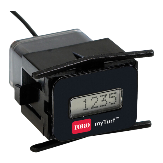
Wireless Hour Meter Kit
Workman
Model No. 136-6323
Model No. 136-6324
This product contains a chemical or chemicals known to the State of California to
Loose Parts
Use the chart below to verify that all parts have been shipped.
Description
No parts required
Wireless hour meter wire harness
Wireless hour meter wire harness
Relay (48 V)
Screw (#4 x 3/4 inch)
Preparing the Machine
1. Park the machine on a level surface.
2. Engage the parking brake.
3. Shut off the engine and remove the key.
© 2017—The Toro® Company
8111 Lyndale Avenue South
Bloomington, MN 55420
®
GTX Utility Vehicle
WARNING
CALIFORNIA
Proposition 65 Warning
cause cancer, birth defects, or reproductive harm.
Qty.
–
1
1
1
2
Register at www.Toro.com.
Prepare the machine.
Install the wireless hour meter (for gasoline machines).
Install the wireless hour meter (for electric machines).
Figure 1
Original Instructions (EN)
Form No. 3413-421 Rev A
Installation Instructions
Use
All Rights Reserved *3413-421* A
Printed in the USA
g038447
Advertisement

Related Manuals for Toro 136-6323


Summary of Contents for Toro 136-6323
- Page 1 Form No. 3413-421 Rev A Wireless Hour Meter Kit Workman ® GTX Utility Vehicle Model No. 136-6323 Model No. 136-6324 Installation Instructions WARNING CALIFORNIA Proposition 65 Warning This product contains a chemical or chemicals known to the State of California to cause cancer, birth defects, or reproductive harm.
- Page 2 Installing the Wireless Hour Meter (for Gasoline Machines) 1. Disconnect the existing female 2-socket connector from the existing hour meter and plug it into the male 2-pin connector on the wireless hour meter wire harness (Figure 2 Figure g206423 Figure 3 1.
- Page 3 Installing the Wireless 4. Connect the female 4-socket connector on the wireless hour meter wire harness to the male 4-pin connector Hour Meter (for Electric on the existing 12 V converter (Figure Machines) 1. Disconnect the existing female 2-socket connector from the existing hour meter and plug it into the male 2-pin connector on the wireless hour meter wire harness...
- Page 4 6. Install the relay to the left fender using 2 screws (#4 x 3/4 inch) as shown in Figure g205529 Figure 8 1. Screw (#4 x 3/4 inch) 3. Left fender 2. Relay 7. Connect the wireless hour meter wire harness connectors to the relay as shown in Figure g205526...