Table of Contents
Advertisement
Quick Links
Advertisement
Table of Contents

Related Manuals for THORLABS K10CR1


Summary of Contents for THORLABS K10CR1
- Page 1 K10CR1 Motorized Cage Rotator User Guide Original Instructions...
-
Page 2: Table Of Contents
Contents Chapter 1 For Your Safety ................3 1.1 Safety Information .................. 3 1.2 General Warnings .................. 3 Chapter 2 Overview ..................4 2.1 Introduction ..................... 4 2.2 APT Software Overview ................. 5 Chapter 3 Mechanical Installation .............. 10 3.1 Unpacking .................... 10 3.2 Environmental Conditions .............. -
Page 3: Chapter 1 For Your Safety
Chapter 1 For Your Safety 1.1 Safety Information For the continuing safety of the operators of this equipment, and the protection of the equipment itself, the operator should take note of the Warnings, Cautions and Notes throughout this handbook and, where visible, on the product itself. The following safety symbols may be used throughout the handbook and on the equipment itself. -
Page 4: Chapter 2 Overview
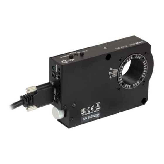
Chapter 2 Overview 2.1 Introduction The Kinesis K10CR1 is a compact, precision motorized rotation mount that accepts Ø1" optics and SM1-threaded components. It is also compatible with our 30 mm cage systems (and 60 mm cage systems when used with adapter K10CR1A3) Rotation is driven via a stepper motor equipped with high ratio worm gear (120:1). -
Page 5: Apt Software Overview
2.2 APT Software Overview 2.2.1 Introduction As a member of the APT range of controllers, the K10CR1 stages share many of the associated software benefits. This includes USB connectivity (allowing multiple units to be used together on a single PC), fully featured Graphical User Interface (GUI) panels, and extensive software function libraries for custom application development. - Page 6 Chapter 2 2.2.2 APTUser Utility The APTUser application allows the user to interact with a number of APT hardware control units connected to the host PC. This program displays multiple graphical instrument panels to allow multiple APT units to be controlled simultaneously. All basic operating parameters can be altered and, similarly, all operations (such as motor moves) can be initiated.
- Page 7 With the APT system, ActiveX Controls are deployed to allow direct control over (and also reflect the status of) the range of electronic controller units, including the K10CR1 stages. Software applications that use ActiveX Controls are often referred to as 'client...
- Page 8 Basic, Labview, Visual C++, C++ Builder, HPVEE, Matlab, VB.NET, C#.NET and, via VBA, Microsoft Office applications such as Excel and Word. Consider the ActiveX Control supplied for the K10CR1 integrated stage & controller. This Control provides a complete user graphical instrument panel to allow the stage...
- Page 9 Additional software developer support is provided on our website. 2.2.5 Software Upgrades Thorlabs operate a policy of continuous product development and may issue software upgrades as necessary. The latest software can be downloaded from the ‘services’ section of www.thorlabs.com.
-
Page 10: Chapter 3 Mechanical Installation
Chapter 3 Mechanical Installation 3.1 Unpacking Note Retain the packing in which the unit was shipped, for use in future transportation. Caution Once removed from its packaging, the stage is easily damaged by mishandling. The unit should only be handled by its base, not by the motor or any attachments to the moving platform. - Page 11 K10CR1 Cage Rotation Stage The casing of the K10CR1 is fitted with a series of holes for mounting the unit in a 30 mm cage system (see Fig. 3.1 and Fig. 3.3). The K10CR1A3 adapter plate allows the stage to be fitted within a 60 mm cage system.
-
Page 12: Transportation
Chapter 3 Fig. 3.2 K10CR1 Stage with K10CR1A1 and K10CR1A2 Adapter Plates Fitted 3.4 Transportation Caution When packing the unit for shipping, use the original packing. If this is not available, use a strong box and surround the unit with at least 100 mm of shock absorbent material. -
Page 13: Dimensions
K10CR1 Cage Rotation Stage 3.5 Dimensions 3.5.1 K10CR1 Dimensions All dimensions in millimeters (inches) 12.5 (0.5”) 11.0 (0.43”) M4 (8-32 UNC) 5.0 (0.2”) 2 PLACES FOR POST MOUNTING 16.0 (0.63”) 29.0 (1.14”) Ø 6.0 (0.24”) 2 PLACES 66.0 (2.6”) (Note A) 35.5 (1.4”) - Page 14 Chapter 3 M3 (4-40 UNC) 6.0 mm (0.24”) M3 (4-40 UNC) 6.0 mm (0.24”) (2 PLACES) (4 PLACES) FOR USE WITH ADAPTOR FOR USE WITH K6A1 K10CR1A2 PLATFORM MOUNT SM1 THREAD 21.8 mm 30.9 mm (1.22”) (0.86”) 30.0 mm 4-40 UNC 3.5 mm (0.137”) MAX (1.18”) THIS AND OPPOSITE SIDE...
-
Page 15: Chapter 4 Software & Electrical Installation
To minimize the possibility of this happening it is strongly recommended that any such modes that result in prolonged unresponsiveness be disabled before the APT software is run. Please consult your system administrator or contact Thorlabs technical support for more details. Caution Some PCs may have been configured to restrict the users ability to load software, and on these systems the software may not install/run. -
Page 16: Connector Detail
Chapter 4 4.3 Connector Detail The side of the unit is fitted with a number of connectors as shown below:. Fig. 4.1 Power and USB Connectors USB/Power - Provides connection to the PC USB port or the USB hub. Although the port is designed to mate with a USB 3.0 connector, it can also be used with a ‘USB Micro B’... - Page 17 K10CR1 Cage Rotation Stage 4) Wait for the unit to initialize (about 5 sec). Do not press any controls during this time. The ENABLE LED is lit when the unit is ready for use. 5) Windows should detect the new hardware. Wait while Windows installs the drivers for the new hardware.
-
Page 18: Verifying Software Operation
4.5 Verifying Software Operation 4.5.1 Initial Setup 1) Run the APTUser utility and check that the Graphical User Interface (GUI) panel appears and is active. Fig. 4.3 Gui panel showing jog and ident buttons 2) Check that the correct stage type and serial number are displayed in the GUI panel. -
Page 19: Chapter 5 Operation
The unit is shipped with a set of default parameters already loaded, and can be operated via the buttons on the top face of the unit. Fig. 5.1 K10CR1 Buttons and LEDs Active LED - Yellow LED, lit when the stage is in motion. Flashes when the Ident button on the GUI panel is clicked - see Section 4.5.1.. - Page 20 Chapter 5 5.3.2 Go to Position Each button can be programmed with a different position value, such that the controller will move the motor to that position when the specific button is pressed. This mode of operation is enabled by setting the ‘Button Mode’ parameter to ‘Go To Position’...
-
Page 21: Using The Apt User Utility
(such as motor moves) can be initiated. Hardware configurations and parameter settings can be saved to a file, which simplifies system set up whenever APT User is run up. Fig. 5.2 Typical APT User Screen 1) Run the APT User program - Start/All Programs/Thorlabs/APT User/APT User. -
Page 22: Homing Motors
Chapter 5 5.5 Homing Motors Homing the motor moves the actuator to the home limit switch and resets the internal position counter to zero. The limit switch provides a fixed datum that can be found after the system has been powered up. Fig. -
Page 23: Moving To An Absolute Position
K10CR1 Cage Rotation Stage 5.6 Moving to an Absolute Position Absolute moves are measured in real world units (e.g. degrees), relative to the Home position. 1) Click the position display. Fig. 5.4 Absolute Position Popup Window 2) Enter 3.0 into the pop up window 3) Click ‘OK’. -
Page 24: Changing Motor Parameters
Chapter 5 5.8 Changing Motor Parameters Moves are performed using a trapezoidal or S-Curve velocity profile (see Appendix C , Section C.1.3.). The velocity settings relate to the maximum velocity at which a move is performed, and the acceleration at which the motor speeds up from zero to maximum velocity. -
Page 25: Jogging
K10CR1 Cage Rotation Stage 5.9 Jogging During PC operation, the motor actuators are jogged using the GUI panel arrow keys. There are two jogging modes available, ‘Single Step’ and ‘Continuous’. In ‘Single Step’ mode, the motor moves by the step size specified in the Step Distance parameter. -
Page 26: Graphical Control Of Motor Positions (Point And Move)
All units are displayed in real world units, i.e. millimetres. Note. For single channel units such as the K10CR1, the Channel 2 parameters are greyed out. The left hand display shows a circle, which represents the current position of the stage associated with the ActiveX Control Instance (absolute position data is displayed in the 'Chan Pos' field). - Page 27 K10CR1 Cage Rotation Stage Move Mode When ‘Move’ is selected, the motors move to an absolute position which corresponds to the position of the cursor within the screen. To specify a move: 1) Position the mouse within the window. For reference, the absolute motor position values associated with the mouse position is displayed in the 'Cursor Position field.
-
Page 28: Setting Move Sequences
Chapter 5 5.11 Setting Move Sequences This section explains how to set move sequences, allowing several positions to be visited without user intervention. For details on moving to absolute positions initiated by a mouse click – see Section 5.10. 1) From the Motor GUI Panel, select 'Move Sequencer' tab to display the Move Sequencer window. - Page 29 K10CR1 Cage Rotation Stage 3) Select 'New' to display the 'Move Editor' panel. Fig. 5.10 Move Editor Window Move data is entered/displayed as follows: Dist/Pos: - the distance to move from the current position (if 'Relative' is selected) or the position to move to (if 'Absolute' is selected).
- Page 30 Chapter 5 4) Enter the required move data into the Move Editor and click OK. The move data is displayed in the main window as shown below. Fig. 5.11 Main Window with Move Data 5) Repeat step 4 as necessary to build a sequence of moves. Move data can be copied, deleted, cut/pasted and edited by right clicking the data line(s) and selecting the appropriate option in the pop up menu (shown below).
-
Page 31: Minimum And Maximum Position Settings
Min Pos and Max Pos values. This check is done to ensure that the position counter always shows a correct value. For the K10CR1 stage, the Min Pos and Max Pos limits are equivalent to around ±43 full rotations (15,480 degrees). -
Page 32: Creating A Simulated Configuration Using Apt Config
To create a simulated configuration proceed as follows: 1) Run the APT Config utility - Start/All Programs/Thorlabs/APT/APT Config. 2) Click the 'Simulator Configuration' tab. Fig. 5.15 APT Configuration Utility - Simulator Configuration Tab 3) Enter a configuration file name, e.g. - Page 33 K10CR1 Cage Rotation Stage 4) In the 'Simulator' field, check the ‘Enable Simulator Mode’ box. The name of the most recently used configuration file is displayed in the 'Current Configuration' window. 5) In the ‘Control Unit’ field, select the K10CR1 Stage type.
- Page 34 8 digits (as displayed in the ‘Load Configuration Details’ window, the first two digits are added automatically and identify the type of control unit. The prefixed digits relating to the K10CR1 stage is: 55xxxxxx - K10CR1 Motorized Stage 7) Click the 'Add' button.
-
Page 35: Chapter 6 Software Reference
Fig. 6.1 K10CR1 Software GUI Note The serial number of the K10CR1 stage associated with the GUI panel, the APT server version number, and the version number (in brackets) of the embedded software running on the unit, are displayed in the top right hand corner. - Page 36 Chapter 6 Enable - applies power to the motor. With the motor enabled, the associated Channel LED on the front panel is lit. Digital display - shows the position (in millimetres) of the motor. The motor must be 'Homed' before the display will show a valid position value, (i.e. the displayed position is relative to a physical datum, the limit switch).
-
Page 37: Settings Panel
K10CR1 Cage Rotation Stage 6.3 Settings Panel When the 'Settings' button on the GUI panel is clicked, the 'Settings' window is displayed. This panel allows motor operation parameters such as move/jog velocities, and stage/axis information to be modified. Note that all of these parameters have... - Page 38 Chapter 6 Jogs Jogs are initiated by using the ‘Jog’ keys on the GUI panel (see Section 5.9.), or via the buttons on the control key pad. Velocity Profile - specified in real world units, (degrees) Note. In current versions of software the ‘Min Vel’ parameter is locked at zero and cannot be adjusted.
- Page 39 K10CR1 Cage Rotation Stage Step Distance - The distance to move when a jog command is initiated. The step size is specified in real world units (mm). Backlash Correction - The system compensates for lead screw backlash during reverse direction moves, by moving passed the demanded position by a specified amount, and then reversing.
- Page 40 Chapter 6 The S-curve profile is a trapezoidal curve with an additional 'Bow Value' parameter, which limits the rate of change of acceleration and smooths out the contours of the motion profile. The Bow Value is applied in degrees/s and is derived from the Bow Index field as follows: (Bow Index -1) Bow Value = 2...
- Page 41 K10CR1 Cage Rotation Stage Persist Settings to Hardware Many of the parameters that can be set for the K10CR1 stages can be stored (persisted) within the unit itself, such that when the unit is next powered up these settings are applied automatically. This is particularly important when the driver is being used manually in the absence of a PC and USB link.
- Page 42 For background information, the individual parameters are described in the following paragraphs. Stage and Axis Type - For K10CR1 stages, the stage type is annotated automatically when the stage is connected. Caution Extreme care must be taken when modifying the stage related settings that follow.
- Page 43 K10CR1 Cage Rotation Stage Homing. Note When homing, the stage moves in the reverse direction, (i.e. towards the home limit switch). This operation is inherent in the design of the stage and the following parameters should not be adjusted. Descriptions are supplied for information only Direction - the direction sense to move when homing, either Forward or Reverse.
- Page 44 Persist Settings to Hardware Many of the parameters that can be set for the K10CR1 stages can be stored (persisted) within the unit itself, such that when the unit is next powered up these settings are applied automatically.
- Page 45 K10CR1 Cage Rotation Stage 6.3.3 Rotation Stages Tab Fig. 6.7 Advanced Settings Absolute Position Reporting Mode This setting relates to the way in which the angular position is displayed on the GUI panel. Equivalent Angle 0 to 360 degrees – The maximum displayed position is 359.99°. If a stage is driven past the 360°...
- Page 46 Chapter 6 6.3.4 Controls Tab Button Control Settings The buttons on the front of the unit can be used either to jog the motor, or to perform moves to absolute positions. Button Mode: This setting determines the type of move performed when the front panel buttons are pressed.
- Page 47 K10CR1 Cage Rotation Stage Right/Bottom Button Pos.: The position to which the motor will move when the ‘Forward’ button is pressed. Note A ‘Home’ move can be performed by pressing and holding both buttons for 2 seconds. This function is irrespective of the ‘Button Mode’ setting.
- Page 48 Chapter 6 Abs Move (Trig Rise) – an absolute move (specified using the latest MoveAbsolute or MoveAbsoluteEx method settings) is initiated on the specified channel when a rising edge input signal is received on the TRIG IN connector. Abs Move (Trig Fall) – as above, but the absolute move is initiated on receipt of a falling edge signal.
- Page 49 (as set using the SetVelParams method). Persist Settings to Hardware Many of the parameters that can be set for the K10CR1 stages can be stored (persisted) within the unit itself, such that when the unit is next powered up these settings are applied automatically.
- Page 50 Chapter 6 6.3.5 Triggering Latency The detection of whether a trigger condition has occurred is carried out periodically at 102 µs intervals. As a result, there is a maximum 102 µs delay between the condition occurring and the trigger output being updated. The following timing diagram illustrates this latency: Trigger condition occurs time...
- Page 51 K10CR1 Cage Rotation Stage 6.3.6 Defaults Tab Fig. 6.9 Defaults Tab If adjustment of the parameter values previously described has resulted in unstable or unsatisfactory system response, this tab can be used to reset all parameter values to the factory default settings.
-
Page 52: Appendix A Specifications
Appendix A Appendix A Specifications A.1 Stage Specifications Parameter Value Travel Range 360° Continuous Max Speed 10 °/s Min Speed 0.005 °/s Max Acceleration 20° /s/s *Note The acceleration is limited by the motor force, and must be reduced for higher loads. ±... - Page 53 K10CR1 Cage Rotation Stage A.2 Design Specification Parameter Value Base Material Aluminum Bearing Type 4-point Ball Bearing Drive Mechanism Worm Gear, Ratio 1:120 Homing Limit Switch Hall Effect Central Aperture SM1 Threaded Operating Temperature Range 5 to 40°C (41 to 104°F)
- Page 54 Chapter 6 A.3 Load Capacity Specifications Parameter Value Max Load (Q) 22 N (2.25 kg or 5.0 lbs) Max Torque (Mz) 140 mNm 1.5 Nm Max Transversal Torque (Mx) Typical Stiffness (Ka) 380 µrad/Nm Fig. A.1 Load Capacity Definitions HA0338T Rev C July 2022...
-
Page 55: Appendix B Motor Control Method Summary
K10CR1 Cage Rotation Stage Appendix B Motor Control Method Summary The 'Motor' ActiveX Control provides the functionality required for a client application to control one or more of the APT series of motor controller units. To specify the particular controller being addressed, every unit is factory programmed with a unique 8-digit serial number. - Page 56 Appendix B GetHomeParams Gets the homing sequence parameters. GetHomeParams_HomeVel Gets the homing velocity parameter (returned by value). GetHomeParams_ZeroOffset Gets the homing zero offset parameter (returned by value). GetHWCommsOK Gets the hardware communications OK flag. GetHWLimSwitches Gets the limit switch configuration settings. GetJogMode Gets the jogging button operating modes.
- Page 57 K10CR1 Cage Rotation Stage GetStatusBits_Bits Gets the controller status bits encoded in 32 bit integer (returned by value). GetTriggerParams Gets the move triggering parameters. GetVelParamLimits Gets the maximum velocity profile parameter limits. GetVelParams Gets the velocity profile parameters. GetVelParams_Accn Gets the move acceleration (returned by value).
- Page 58 Chapter 6 SetEncPosCorrectParams Sets the encoder position correction parameters for encoder equipped stages. SetHomeParams Sets the homing sequence parameters. SetHWLimSwitches Sets the limit switch configuration settings. SetJogMode Sets the jogging button operating modes. SetJogStepSize Sets the jogging step size. SetJogVelParams Sets the jogging velocity profile parameters.
-
Page 59: Appendix C Stepper Motor Operation
C.1 How A Stepper Motor Works C.1.1 General Principle Thorlabs’ actuators use a stepper motor to drive a precision lead screw. Stepper motors operate using the principle of magnetic attraction and repulsion to convert digital pulses into mechanical shaft rotation. The amount of rotation achieved is directly proportional to the number of input pulses generated and the speed is proportional to the frequency of these pulses. - Page 60 Appendix C C.1.2 Positive and Negative Moves Positive and negative are used to describe the direction of a move. A positive move means a move from a smaller absolute position to a larger one, a negative move means the opposite. In the case of a linear actuator, a positive move takes the platform of the stage further away from the motor.
- Page 61 K10CR1 Cage Rotation Stage The S-curve profile is a trapezoidal curve with an additional 'Bow Value' parameter, which limits the rate of change of acceleration and smooths out the contours of the motion profile. The Bow Value is specified in degrees/s...
- Page 62 Appendix C C.2 Positioning a Stage C.2.1 General Whenever a command is received to move a stage, the movement is specified in motion units, (e.g. millimetres). This motion unit value is converted to microsteps before it is sent to the stage. If operating the unit by the front panel (local mode) this conversion is performed internally by the controller.
- Page 63 K10CR1 Cage Rotation Stage Movement is allowed right through the switch position in either direction. Datum switch +ve limit switch -ve limit switch (or stop) Linear stage Rotary stage Fig. C.4 Stage limit switches C.2.4 Power Saving The current needed to hold a motor in a fixed position is much smaller than the current needed to move it, and it is advantageous to reduce the current through a stationary motor in order to reduce heating.
- Page 64 Chapter 6 C.3 Error Correction C.3.1 Backlash correction The term backlash refers to the tendency of the stage to reach a different position depending on the direction of approach. Backlash can be overcome by always making the last portion of a move in the same direction, conventionally the positive direction.
-
Page 65: Appendix D Regulatory
K10CR1 Cage Rotation Stage Appendix D Regulatory D.1 Declarations Of Conformity D.1.1 For Customers in Europe A CE certificate is included in Section D.3. D.1.2 For Customers In The USA This equipment has been tested and found to comply with the limits for a Class A digital device, persuant to part 15 of the FCC rules. - Page 66 • left over parts of units disassembled by the user (PCB's, housings etc.). If you wish to return a unit for waste recovery, please contact Thorlabs or your nearest dealer for further information. D.2.2 Waste treatment on your own responsibility If you do not return an "end of life"...
- Page 67 K10CR1 Cage Rotation Stage D.3 CE Certificates...
- Page 68 "End of life" units must be returned to Thorlabs or handed to a company specializing in waste recovery. Do not dispose of the unit in a litter bin or at a public waste disposal site.
- Page 69 www.thorlabs.com...
Need help?
Do you have a question about the K10CR1 and is the answer not in the manual?
Questions and answers