
Related Manuals for THORLABS PM100


Summary of Contents for THORLABS PM100
- Page 1 Operation Manual Thorlabs Instrumentation Optical Power Meter System PM120, PM121, PM122, PM130, PM132, PM140, PM144 PM210, PM212, PM213 2006...
- Page 2 Version: 1.22 M0009-510-401 Date: 12.05.2006 © Copyright 2006, Thorlabs...
-
Page 3: Table Of Contents
Inserting and Charging the Battery Pack 3.4.2 Switching On and Off the Unit 3.4.3 Principal of Operation and Menu Navigation 3.4.4 Connecting a Photodiode Sensor (PM100 Series) 3.4.4.1 Dark current adjustment 3.4.4.2 Wavelength Correction 3.4.4.3 Attenuation/Gain Correction 3.4.5 Connecting a Thermal Sensor (PM200 series) 3.4.5.1 Zeroing the Sensor... - Page 4 6.1 General Care 6.2 Cleaning 6.3 Line Voltage 6.4 Repair Listings 7.1 Default Settings 7.2 List of figures 7.3 Certifications and Compliances 7.4 Thorlabs “End of Life” policy (WEEE) 7.4.1 Waste treatment on your own responsibility 7.4.2 Ecological background 7.5 Addresses...
- Page 5 Therefore, please let us know about possible criticism or ideas. We and our international partners are looking forward to hearing from you. Thorlabs This part of the instruction manual contains every specific information on how to handle and use the PMxxx Optical Power Meter system. A general description is followed by explanations of how to operate the unit remotely via the serial RS232 connection.
-
Page 7: Safety
Operate the power meter only within the specified voltage range Do not apply voltage outside the specified range of the input connec- tions Do not operate the power meter if there are suspected failures. Refer damaged units to qualified Thorlabs service personnel PM100 / page 1... - Page 8 Standard shielding and filtering measures have to be undertaken to avoid interferences with other electronic equipment! NOTE Please check prior to operation, if the line voltage range, indicated on the power supply agrees with your local supply PM100 / page 2...
-
Page 9: Getting Started Quickly
2.1 Setup • Carefully unpack the console, optical head and accessories. If any of the items are damaged, do not use the meter. Call Thorlabs and arrange for replace- ment. • Install the NiMH battery pack; therefore turn the unit, set the battery pack in its socket and push it slightly in top direction of the meter, until it snaps in. - Page 10 The arrow keys are used to navigate through the menus as well as navigating and adjusting the display soft keys. Enter Key The enter key is used to get into child menus and confirm user settings PM100 / page 4...
-
Page 11: Display Arrangement
Menu tune graph) measurement displays Auto-Range Measurement Relative display: indicator: Shows range indicator If REL∆ is activated the up when auto- difference to zero is range is activated indicated in this button Figure 1 Display Arrangement PM100 / page 5... -
Page 12: Description
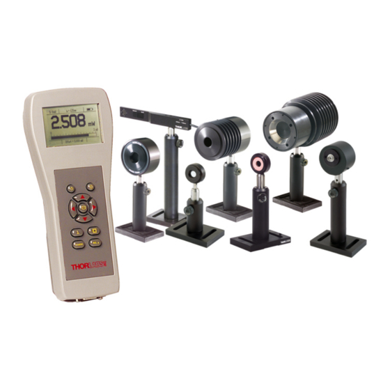
LCD read-out and is controlled by an easy-to-use keypad. Thorlabs offers a wide range of interchangeable sensor heads to use with the PM100 console. Large area silicon and germanium semiconductor heads cover the range from visible to mid IR with nW sensitivity. -
Page 13: Parts List - Accessories
3.1 Parts List – Accessories 3.1 Parts List – Accessories The power meter system consists of the following items: • PM100 Universal power meter console with o PMBAT Rechargeable and replaceable 3.6V 1500mAh NiMH battery pack • CABSER Serial Interface cable; 9p Sub-D female on both ends •... -
Page 14: Technical Data
3.2 Technical Data 3.2 Technical Data (All technical data are valid at 23 ± 5°C and 45 ±15% humidity) 3.2.1 PM100 Display Unit General Specifications: Display: 240 x 160 pixel LCD with EL backlight Display Format: Digit, Analog needle, histogram, statistics and menu... -
Page 15: S120B / S121B Silicon Sensor (Pm120 / Pm121)
800 to 1700nm that can be removed by carefully levering in the side hole with a small screw driver. The sensors can be equipped with fiber adapters from the S120 series. (Order Codes: S120-FC, S120-SMA, S120-SC) For use with metric posts insert the 8-32 to M4 adapter. PM100 / page 9... -
Page 16: S122B Germanium Sensor (Pm122)
800 to 1700nm that can be removed by carefully levering in the side hole with a small screw driver. The sensor can be equipped with fiber adapters from the S120 series. (Order Codes: S120-FC, S120-SMA, S120-SC) For use with metric posts insert the 8-32 to M4 adapter. PM100 / page 10... -
Page 17: S130A / S132B Slim Sensor (Pm130 / Pm132)
The sensor contains two sets of calibration data for both slider positions. The console automatically uses the right calibration data a few seconds after the slider has been moved. Please care that the slider is always in a “snapped” position. PM100 / page 11... -
Page 18: S140A / S144A Integrating Sphere Sensor (Pm140 / Pm144)
To remove or change the fiber adapter, loosen the two M2.5x5 screws and lift-off the adapter. Fiber adapters are available for SMA connectors (S140-SMA) and SC connectors (S140-SC). With removed fiber adapter the sensor can be used in free-space applications. PM100 / page 12... -
Page 19: S210A 3W Thermal Sensor (Pm210)
20mW – 3W Resolution: Measurement Standard: NIST traceable Measurement uncertainty: +/- 5% Optical damage threshold: 200W/cm² 3.3J/cm² (1ms pulse @ 1064nm) 50mJ/cm² (20ns pulse @ 1064nm) Size: 33.0mm x ∅63.5mm (1.3” x ∅2.5”) Weight: 0.51kg (1.13lbs) PM100 / page 13... -
Page 20: S212A 10W Thermal Sensor (Pm212)
20mW – 10W Resolution: Measurement Standard: NIST traceable Measurement uncertainty: +/- 5% Optical damage threshold: 200W/cm² 3.3J/cm² (1ms pulse @ 1064nm) 50mJ/cm² (20ns pulse @ 1064nm) Size: 81.3mm x ∅63.5mm (3.2” x ∅2.5”) Weight: 0.51kg (1.13lbs) PM100 / page 14... -
Page 21: S213A 30W Thermal Sensor (Pm213)
100mW – 30W Resolution: Measurement Standard: NIST traceable Measurement uncertainty: +/- 5% Optical damage threshold: 200W/cm² 3.3J/cm² (1ms pulse @ 1064nm) 50mJ/cm² (20ns pulse @ 1064nm) Size: 92.5mm x ∅63.5mm (3.64” x ∅2.5”) Weight: 0.51kg (1.13lbs) PM100 / page 15... -
Page 22: Physical Overview
3.3 Physical Overview On/Off Backlight Enter Wavelength correction (Photodiode heads) Navigation Range Menu Display Selection Zero / Relative Measurement Figure 2 PM100 Operating Elements DB9 Sensor Jack SMA Analog Output Jack Figure 3 Top Plate Operating Elements PM100 / page 16... -
Page 23: Operating Instruction
AC outlet. Attach the right adapter depending on local power requirements to the power supply, adapters for US, Europe and UK are provided with the instrument. If the adapter is lost, contact Thorlabs for replacement. PM100 / page 17... -
Page 24: Switching On And Off The Unit
When the 9VDC adaptor is applied a “loading battery symbol” remains in the display when the unit is switched off. 3.4.3 Principal of Operation and Menu Navigation The PM100 uses the following types of operating elements: • Navigating field with arrow and enter buttons • Display soft keys •... -
Page 25: Connecting A Photodiode Sensor (Pm100 Series)
• Toggle the 5 preset correction wavelengths (short) • Edit a preset correction wavelength (long) 3.4.4 Connecting a Photodiode Sensor (PM100 Series) Plug the DB-9 connector of the optical head into the jack located on the top of the console and secure the two screws. This can be done while the power meter is switched on. -
Page 26: Dark Current Adjustment
To achieve accurate measurement results this dark current must be considered and subtracted from the power reading. Even though the PM100 is capable to store and recall the dark currents from 5 different sensors it is recommended to conduct the following procedure from time to time to exclude failures caused by the temperature dependency of the dark current. -
Page 27: Attenuation/Gain Correction
Enter. Leave the menu with the left arrow or any function button. Whenever the PM100 is switched off (also by auto-shutdown) the last wavelength used will be stored. The next time the unit is powered up this wavelength will be in effect. -
Page 28: Zeroing The Sensor
• Enter the Menu, toggle down to menu #3 ‘User Calibration’ and press Enter • Set the calibration factor in logarithmic representation (dB) by using the arrow buttons. The system allows input values between -20dBm and +30dBm PM100 / page 22... -
Page 29: Range Setting
Enter and the up/down buttons toggle the relative measurement on and off. When the REL∆ function is activated, the bar-graph and analog needle display go to a middle-positioned scale with an automatic zoom by a factor of 10. PM100 / page 23... -
Page 30: Zoom Functions
3.4.9 Representation of the Optical Power Reading The Display function button allows to toggle between different represen- tations of the optical power reading. The PM100 enables numerical, quasi-analog and statistical display functions for the power read out. The different display are also accessible by pressing the up and down arrow buttons, when the Menu soft key is activated. -
Page 31: Digital Needle Display
Pressing the REL∆ button zeros the display and indicates the offset value in the button. The needle scale will be zoomed by factor 10 and go into a middle scale position. Abs. indicates an absolute reading (REL∆ is deactivated) PM100 / page 25... -
Page 32: Tune-Graph Display
Ranges are set in logarithmic half decade cycles (3, 10, ..) by pressing the up and down arrow buttons. Over or under- range is indicated by up and down arrows on the left side of the power axis. PM100 / page 26... -
Page 33: Statistics Display
When REL∆ is activated the units change from dBm to dB, over or under-range conditions are displayed by Hi and Lo indicators above the units. λ1 = 780 nm a = 10.00 dB Si 50mW 7.123 8.473 10 mW Abs. Menu Figure 10 Power dBm Display PM100 / page 27... -
Page 34: Menu Structure And Description Of The Additional Functionality
To safe battery power set the time as short as possible. Contrast Adjusts the display contrast. The contrast can be set as a num- ber of percentage. The result can be watched online while adjusting the contrast control. Line Filter PM100 / page 28... -
Page 35: Special Topics
The wavelengths can be entered with 1nm precision. Note, that a semiconductor sensor with wavelength correction table has to be con- nected to the instrument. The PM100 will store and recall the preset wavelength settings for up to 5 different sensors. -
Page 36: Backlight
(factory default 5 seconds). 3.4.11.3 Processor Reset The PM100 uses a sophisticated microprocessor with non-volatile memory to store system values when the unit is powered off. Under normal conditions, it should not be necessary to reset the system. However, if the system locks up and does not respond to any key presses, it may be necessary to reset the unit by pressing the reset key in the bottom plate of the console. -
Page 37: Computer Interface
PC use the 9-pole null-modem cable that is provided with the optical power meter system. Plug one end to the DB9 socket in the bottom plate of the PM100, the other end to a free COM port of the PC. -
Page 38: Data Format
Examples: Hello , ”Good luck” , ’How are you?’ 4.2.2 Response Data Elements The device responds with Response Data Elements. These elements typically contain measurement results, settings, or status information. Response Data Elements are defined by IEEE488.2-1992. The device uses the following elements: PM100 / page 32... - Page 39 16 numeric information. Examples: #H1E <STRING PROGRAM DATA> A <STRING PROGRAM DATA> element allows any character in the ASCII code to be transmitted as a message. Examples: Hello , ”Good luck” , ’How are you?’ PM100 / page 33...
-
Page 40: Ieee Emulation Codes
1. The device sends ‘&SRQ<CR><LF>’ to the controller showing that it requires service. 2. The controller has to respond with ‘&POL’ to query the device’s Status Byte. 3. The device then responds by sending ‘&ddd<CR><LF>’ where ‘ddd’ is the 3 digit decimal value of the Status Byte. PM100 / page 34... -
Page 41: Commands
Service Request Enable query. (IEEE488.2-1992-§10.35) *SRE? Read Status Byte query. (IEEE488.2-1992-§10.36) *STB? Standard Event Status Enable command. (IEEE488.2-1992- *ESE §10.10) Standard Event Status Enable query. (IEEE488.2-1992-§10.11) *ESE? Standard Event Status Register query. (IEEE488.2-1992-§10.12) *ESR? Clear Status command. (IEEE488.2-1992-§10.3) *CLS PM100 / page 35... -
Page 42: Common Command Description
The Operation Complete Query places a ‘1’ into the device’s Description: output queue (see also IEEE488.2-1992-§10.19). Wait Command Command syntax: *WAI Response syntax: None Description: This command is required for IEEE488 compatibility and has no effect. (see also IEEE488.2-1992-§10.39). PM100 / page 36... - Page 43 Command syntax: *ESE <NR1> Response syntax: None Description: Sets the device’s Standard Event Status Enable Register (see also IEEE488.2-1992-§10.10 and Chapter ‘Status Reporting’). Standard Event Status Enable Query Command syntax: *ESE? Response syntax: <NR1 NUMERIC RESPONSE DATA> PM100 / page 37...
- Page 44 Clears the following device’s status registers (see also IEEE488.2-1992-§10.3): • Standard Event Status Register • Device Error Event Register and Device Error Event Enable Register • Device State Event Register and Device State Event Enable Register PM100 / page 38...
-
Page 45: Device Specific Commands
Query the currently set attenuation correction (this is an :ATTENUATION? additional attenuation set by the user to e.g. compensate for additional filters) Set the attenuation correction (this is an additional :ATTENUATION attenuation the user can set to compensate for e.g. additional filters) PM100 / page 39... -
Page 46: Device Specific Command Description
:WAVELENGTH <DECIMAL NUMERIC PROGRAM DATA> Response syntax: None Description: Set the wavelength [meter] to use for calculating the sensitivity Wavelength Range Query Command syntax: :WAVELENGTH:RANGE? minimum settable wavelength <NR3 NUMERIC RESPONSE Response syntax: DATA> maximum settable wavelength <NR3 NUMERIC RESPONSE PM100 / page 40... - Page 47 Dark Current Query Command syntax: :DARKCURRENT? dark current <NR3 NUMERIC RESPONSE DATA> Response syntax: Description: Queries the set value for the photo diode dark current value [amperes]; works with Si/Ge sensors only PM100 / page 41...
- Page 48 This is to compensate for additional attenuation caused by e.g. filter glass. Set Attenuation Correction Command syntax: :ATTENUATION <DECIMAL NUMERIC PROGRAM DATA> Response syntax: None Description: Sets the value for the attenuation [dB] a user can set to PM100 / page 42...
-
Page 49: Status Reporting
0 No error 1 General fault Device Dependent Error 2 Value out of range Execution Error 20 Wrong command for used head Execution Error 100 Input buffer overflow Command Error 101 Unknown IEEE488 emulation command Command Error PM100 / page 43... - Page 50 113 String program data too long Command Error 114 Erroneous non-decimal program data Command Error 115 Erroneous decimal program data Command Error 200 Authentication required for operation Execution Error 201 Authentication failed Execution Error 255 Error queue overflow PM100 / page 44...
-
Page 51: Calibration And Warranty
For warranty repairs or service the unit must be sent back to or to a place Thorlabs determined by Thorlabs. The customer will carry the shipping costs to Thorlabs, in case of warranty repairs will carry the shipping costs back to the customer. - Page 52 Thorlabs explicitly not warrant the usability or the economical use for certain cases of application. reserves the right to change this instruction manual or the technical data of Thorlabs the described unit at any time. PM100 / page 46...
-
Page 53: Service And Maintenance
Do not try to open the power supply! Dangerous or even lethal voltages inside. 6.1 General Care Protect the PM100 from adverse weather conditions. The PM100 is not water resistant. Attention To avoid damage to the PM100, do not expose it to spray, liquids or solvents! PM100 / page 47... -
Page 54: Cleaning
Thorlabs service department for repair or replacement. 6.3 Line Voltage The power supply of the PM100 operates at line voltages of 100 V … 240 V ± 10% and line frequencies of 50 and 60Hz. Prior to starting operation check that your local supply agrees with this line voltage range. -
Page 55: Listings
7.1 Default Settings 7 Listings 7.1 Default Settings The PM100 measurement system comes with the following factory settings: Setting Default Autorange Enabled Analog Output 0.1V/mW Display Refresh Rate Shutdown 10 minutes Backlight 5 seconds Contrast Line Filter 50Hz Wavelength Correction Silicon Sensors: 1: 635nm;... -
Page 56: List Of Figures
Figure 4 Bottom Plate Operating Elements Figure 5 Inserting/Removing the Battery Pack Figure 6 Power (Watts) and Bar-Graph Display Figure 7 Digital Needle Display Figure 8 Tune-Graph Display Figure 9 Statistics Display Figure 10 Power dBm Display PM100 / page 50... -
Page 57: Certifications And Compliances
The power supply must be propperly filtered! Emissions which exceed the levels required by these standards, may occur when this equipment is connected to a test object. PM100 / page 51... -
Page 58: Thorlabs "End Of Life" Policy (Weee)
7.4.1 Waste treatment on your own responsibility If you do not return an “end of life” unit to Thorlabs, you must hand it to a company specialized in waste recovery. Do not dispose of the unit in a litter bin or at a public waste disposal site. -
Page 59: Ecological Background
7.4 Thorlabs “End of Life” policy (WEEE) 7.4.2 Ecological background It is well known that WEEE pollutes the environment by releasing toxic products during decomposition. The aim of the European RoHS directive is to reduce the content of toxic substances in electronic products in the future. -
Page 60: Addresses
7.5 Addresses 7.5 Addresses For technical support or sales inquiries, please visit us at www.thorlabs.com/contact for our most up-to- date contact information. USA, Canada, and South America UK and Ireland Thorlabs, Inc. Thorlabs Ltd. sales@thorlabs.com sales.uk@thorlabs.com techsupport@thorlabs.com techsupport.uk@thorlabs.com Europe Scandinavia...
Need help?
Do you have a question about the PM100 and is the answer not in the manual?
Questions and answers