Table of Contents
Advertisement
Advertisement
Table of Contents

Related Manuals for THORLABS PAX1000


Summary of Contents for THORLABS PAX1000
- Page 1 Compact Polarimeter PAX1000 Operation Manual 2019...
- Page 2 Version: Date: 26-Feb-2019 Copyright © 2019 Thorlabs GmbH...
-
Page 3: Table Of Contents
3.2 GUI Overview 3.3 Menu File 3.4 Menu Device 3.5 Menu View 3.6 Menu Tools 3.7 Menu Help 3.8 Status Bar 4 PAX1000 Settings 5 Operating Instruction 5.1 Alignment Assistance 5.2 PAX1000 Measurements 5.2.1 Measurement Value Table 5.2.2 Polarization Ellipse 5.2.3... - Page 4 Correction of the Polarimeter ER Measurements 9 Appendix 9.1 Technical Data 9.2 Dimensions 9.3 Certifications and Compliances 9.4 Warranty 9.5 Copyright and Exclusion of Reliability 9.6 Thorlabs 'End of Life' Policy 9.7 List of Acronyms 9.8 Literature 9.9 Thorlabs Worldwide Contacts...
- Page 5 Paragraphs preceded by this symbol explain hazards that could damage the instrument and the connected equipment or may cause loss of data. Note This manual also contains "NOTES" and "HINTS" written in this form. Please read this advice carefully! © 2019 Thorlabs GmbH...
-
Page 6: General Information
Each measurement sensor is calibrated at different wavelength points. These base points are interpolated. The PAX1000 is basically powered via the USB port. For a measurement speed higher that 50 samples per second, an additional power supply is required - please connect the DS15 power supply to your mains outlet and to the PAX1000. - Page 7 1 General Information equipment other than those specified by Thorlabs GmbH. The correction of interference caused by such unauthorized modification, substitution or attachment will be the re- sponsibility of the user. The use of shielded I/O cables is required when connecting this equipment to any and all optional peripheral or host devices.
-
Page 8: Ordering Codes And Accessories
Included Accessories: · F240FC-C Fiber Collimator KAD12F SM1 Threaded Adapter for the Fiber Collimator · · SM1M10 SM1 Lens Tube VRC2SM1 alignment disk with mounting adapter · PAX1000IR2/M Same as PAX1000IR2, but with metric mounting threads © 2019 Thorlabs GmbH... -
Page 9: Requirements
® · Windows 8.1 (32-bit, 64-bit) ® · Windows 10 (32-bit, 64-bit) For operation of the PAX1000, the following software is required as well: ® · NI-VISA Runtime (Version 5.4 or later) ® · Microsoft .Net (Version 4.6.1 or later) ®... -
Page 10: Getting Started
If the shipping container seems to be damaged, keep it until you have inspected the contents and you have inspected the PAX1000 mechanically and electrically. Verify that you have received the following items within the package, depending on the ordered item: 1. -
Page 11: Operating Principle
Transformation (FFT) analysis allows then to calculate the 3 normalized Stokes vectors s1, s2 and s3, the polarized power and degree of polarization DOP. These parameters are sufficient to completely describe the polarization state of the light incident on the PAX1000 polarization. Please see section Rotating Waveplate Technique for detailed explanation. -
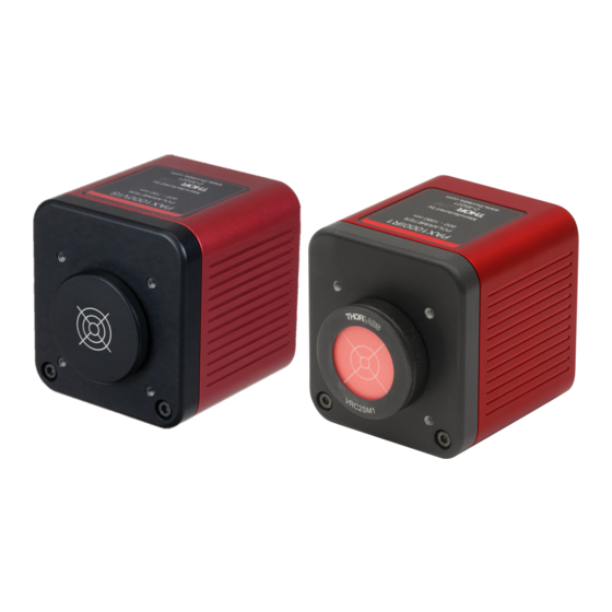
Page 12: Operating Elements
PAX1000 2.3 Operating Elements Operating Elements Front Mounting hole for Thorlabs 30 mm cage system (4-40, depth 5.5 mm), 4 places Input aperture with Thorlabs SM1 (1.035"-40) external thread Input aperture with Thorlabs SM05 (0.535"-40) internal thread PAX1000 Operating Elements (Rear) -
Page 13: Mounting
Appendix. Note It is important to align the incident beam perpendicularly to the front surface of the PAX1000 and centered to its input aperture. The centering can be easily aligned by using the delivered protection cap - the PAX1000VIS comes with an cross-hair engraved end cap (in the picture left), the PAX1000IR1 and PAX1000IR2 come with a mounted viewing target. -
Page 14: Installing Software
The PAX1000 software package contains beside the PAX1000 software a NI VISA Runtime and the Thorlabs DFU Wizard. The latter is required to enable the user to install future firmware updates to the PAX1000. The software package can be downloaded from the website https://www.thorlabs.com/software_pages/ViewSoftwarePage.cfm?Code=PAX1000x... - Page 15 Click 'Next' to continue. In the subsequent dialog windows, follow the instructions. Accepting the proposed settings is recommended.. If you are prompted to restart your computer, please do so to avoid installation issues. © 2019 Thorlabs GmbH...
- Page 16 When you are prompted again to restart your computer, please do so to avoid installation issues. After restarting the computer, the installer automatically resumes the installation process and installs the Thorlabs DFU Wizard: © 2019 Thorlabs GmbH...
- Page 17 2 Getting Started Click 'Next' to continue. In the subsequent dialog windows, follow the instructions. Accepting the proposed settings is recommended. As a next step, the installer continues with installation of the PAX1000 software: © 2019 Thorlabs GmbH...
- Page 18 Click 'Next' to continue. In the subsequent dialog windows, follow the instructions. Accepting the proposed settings is recommended. The Readme screen contains important information, please read it carefully. Then click 'Next'. Click 'Finish' to finalize the installation of the software package. © 2019 Thorlabs GmbH...
-
Page 19: First Steps
Please take into account an initial warm up time of the PAX1000xxx. Note The supplied USB cable is certified for use with the PAX1000. The use of other and / or longer cables may lead to degradation of performance, data loss or even malfunction of the PAX1000. -
Page 20: Graphical User Interface (Gui)
Prior to explaining the GUI in detail, there are some general comments to make about the inter- actions between the PAX1000 hardware and the control software. Please read these com- ments carefully as this information is important to understanding the functionality. -
Page 21: Gui Overview
Status Bar ( ). The ribbons can be minimized and restored using the small icon to the right of the Thorlabs logo. Click to an area of the screenshot below to be directed to the appropriate section for detailed information. -
Page 22: Menu File
JPG, PNG or BMP file. Theme allows to toggle between a light or dark design of the GUI. Exit closes the application. You can use the X icon in the upper right corner of the GUI as well. © 2019 Thorlabs GmbH... - Page 23 3 Graphical User Interface (GUI) Save Configuration This option allows the setup of the GUI and/or the connected PAX1000 polarimeters to be saved. The saved configuration can be loaded later for use in future experiments, or with a dif- ferent optical setup, or copied to and loaded into the software running on a different computer.
- Page 24 PAX1000 Save Measurement The Measurement file is an CSV file that contains: · Device settings and device information of the PAX1000 that was used for measurement. · The most recent 1000 measurement results with time stamp. Open Here you can open a previously save configuration or a measure- ment results file.
-
Page 25: Menu Device
Power Range: The PAX1000 has a large input power dynamic range of 70 dB. To achieve a high measurement accuracy, a switchable gain amplifier is used. Each gain value corresponds © 2019 Thorlabs GmbH... - Page 26 Power Range" is checked). In particular cases it might be useful to fix the power range - un- check the box and set the power range then manually. Device Color: Select a color for the selected PAX1000 instrument. This color will be used for Polarization Ellipse and Poincaré Sphere display of the measurement data. For each connec- ted and active PAX1000 a different color is assigned that can be changed individually.
-
Page 27: Menu View
Click to an icon in the above shown screenshot to view the appropriate manual section. 3.7 Menu Help Troubleshooting Contact Technical Support opens Thorlabs' web site with the list of world-wide contacts. Save Logfile: This file logs the most recent 5 software sessions. -
Page 28: Status Bar
Product License Opens the License.rtf file. About Thorlabs PAX1000 Displays information about the current PAX1000 software. 3.8 Status Bar By default, the status bar displays only the actual date and time: It is used to indicate common errors as well as information about long-term measurement (LtM) -
Page 29: Pax1000 Settings
FFT points. Note When the PAX1000 is powered via USB only, the Basic Sample Rate can be set between 50 and 100 Hz. With external power supply, the maximum Basic Sample Rate is 400 Hz. -
Page 30: Operating Instruction
Click the Start Alignment button. Adjust the alignment of the beam with respect the PAX1000 beam. When the best alignment is achieved, click Stop Alignment and close the window. -
Page 31: Pax1000 Measurements
The PAX1000 software provides several polarization measurement views that can be called from the View ribbon. If this ribbon is hidden, please click the small arrow next to the Thorlabs logo (marked yellow): These views are described in detail in the subsequent sections: Measurement Value Table ·... -
Page 32: Measurement Value Table
Click the drop-down arrow (marked yellow) to expand the list and select the desired parameters. When checking the box of the active PAX1000, all parameters will be enabled, with the pos- sibility to disable any of them. - Page 33 The dSOPs will be displayed in Measurement Value Table this way: By clicking to the area outside the parameter selection window, the parameter selection panel closes and in the GUI will be displayed the table with measurement results: © 2019 Thorlabs GmbH...
-
Page 34: Polarization Ellipse
· Click the colored box to show the current SOP in front. If you have more than one PAX1000 connected, the click shows the current SOP of the selected device. · Hold the left mouse button and drag to rotate the sphere. - Page 35 The 3 buttons to the right provide the following functions: · Saves the current Poincaré sphere orientation and zoom factor as user view.. Recalls the saved user view. · Resets the zoom to default, all other view settings are not impacted. · © 2019 Thorlabs GmbH...
-
Page 36: Scope Mode
Time Format: If a measurement is loaded and selected for display, the time format can be toggled between time stamp and elapsed time. For running measurements (a PAX1000 is se- lected), only the time stamp is used. - Page 37 The yellow marker appears instantly when hovering the mouse over the diagram only if a load- ed measurement is displayed. In live mode, when the measurement of a PAX1000 is displayed, the yellow marker appears only after the mouse wheel was rotated. Then the display of the current measurement is paused and the diagram can be zoomed.
- Page 38 Another way to zoom and pan the diagram is the use of the zoom-pan-sliders to the left and be- low the chart: Pan Diagram Pan Diagram Zoom Diagram Using the Zoom Out button in the diagram header, you can instantly return to the full diagram view: © 2019 Thorlabs GmbH...
-
Page 39: Long Term Measurement
3. Select the Stop criteria: · after reaching a file size between 0.1 and 1000 MB · after reaching a record time 10 sec and 365 days 23:59:59 hours · after recording 1 to 10000 measurement data sets © 2019 Thorlabs GmbH... -
Page 40: Measurement
Start Long-Term Measurement button in the settings panel or the button in the ribbon Tools. The measurement progress is shown in the settings panel and in the status bar on the bottom of the GUI: © 2019 Thorlabs GmbH... -
Page 41: Extinction Ratio Measurement
It is important to couple the linearly polarized light parallel to the slow axis of the fiber under test. The output of the fiber under test is connected to the PAX1000 using the supplied fiber collim- ator with the SM1 adapter. - Page 42 Poincaré Sphere. For reliable ER Measurement results, at least a full circle must be drawn (i.e. the stress must vary enough during the test to result in this min- imum change in polarization state). © 2019 Thorlabs GmbH...
-
Page 43: Er Measurement Wizard
Open the ER Measurement Wizard from the Tools menu. The Start Window summarizes how to set up the measurement. Additional details are given in previous section If necessary, select the PAX1000 for measurement, then click © 2019 Thorlabs GmbH... - Page 44 Select the option Stop on Circle Completed, which will terminate the measurement as soon as the SOP change reached a full circle. When done, click The current SOP is displayed on the Poincaré Sphere. Click to proceed. © 2019 Thorlabs GmbH...
- Page 45 Save the numeric test results and the Poincaré Sphere screenshot to a PDF file. Return to the previous window. Close the ER Measurement Wizard and return to the PAX1000 GUI. Please see the Tutorial in the appendix for detailed explanation of the options...
-
Page 46: Er Measurement Tool
You may select for a first try the maximum time of 10 s and check the box Stop on Circle Completed. 5. Start the fiber stress and the ER measurement. © 2019 Thorlabs GmbH... - Page 47 Radius of the calculated circle in ° on the Poincaré Sphere. Deviation Standard deviation of the Used Points from the approximated circle. If a warning or an error message appears, please see section Troubleshooting for possible reasons and solution proposals. © 2019 Thorlabs GmbH...
-
Page 48: Virtual Device
PAX1000 5.2.7 Virtual Device A virtual PAX1000 can be connected. This is an easy way to evaluate the PAX1000 software without the hardware. This device is based on a PAX1000IR1 with its default settings . These settings cannot be changed. - Page 49 This limitation affects the maximum trace length. If more than one PAX1000 is connected, the maximum number of points that can be displayed on the Poincaré sphere, equal to the maximum trace length, will be shared: 1 PAX1000: max.
-
Page 50: Write Your Own Application
Windows 7, Windows 8.1 and Windows 10 (32 and 64 bit) Note PAX1000 software and drivers contains 32 bit and 64 bit applications. In 32 bit systems, only the 32 bit components are installed to C:\Program Files\…... -
Page 51: Bit Operating Systems
C:\Program Files\Microsoft.NET\Primary Interop Assemblies… …\Thorlabs.PAX1000.Interop.dll C:\Program Files\IVI Foundation\VISA\VisaCom\Primary Interop… …Assemblies\Thorlabs.PAX1000.Interop.dll Example for C Source file: C:\Program Files\IVI Foundation\VISA\WinNT\TLPAX\Examples\CSample\… …sample.c (C program how to communicate with a PAX1000 Series polarimeter) Example for C# Solution file: C:\Program Files\IVI Foundation\VISA\WinNT\TLPAX\Examples… …\CSharp\Thorlabs.PAX_CSharp_Demo.sln © 2019 Thorlabs GmbH... - Page 52 PAX1000 Project file: C:\Program Files\IVI Foundation\VISA\WinNT\TLPAX\Examples… …\CSharp\Thorlabs.PAX_CSharp_Demo\Thorlabs.PAX_CSharp_Demo.csproj Executable sample demo: C:\Program Files\IVI Foundation\VISA\WinNT\TLPAX\Examples… …\CSharp\Thorlabs.PAX_CSharp_Demo\bin\Thorlabs.PAX_CSharp_Demo.exe Example for LabView Included in LabVIEW llb container. © 2019 Thorlabs GmbH...
-
Page 53: Bit Operating Systems
32 bit NI-Labview version C:\Program Files (x86)\National Instruments\LabVIEW xxxx\instr.lib… …\TLPAX\TLPAX.llb 64 bit NI-Labview version C:\Program Files\National Instruments\LabVIEW xxxx\instr.lib… …\TLPAX\TLPAX.llb (LabVIEW container file with driver vi's and an example. "LabVIEW xxxx" stands for actual LabVIEW installation folder.) © 2019 Thorlabs GmbH... - Page 54 C:\Program Files\IVI Foundation\VISA\VisaCom64\… …\Primary Interop Assemblies\Thorlabs.PAX1000_64.Interop.dll Example for C Source file: C:\Program Files (x86)\IVI Foundation\VISA\WinNT\TLPAX\Examples\… …CSample\sample.c (C program how to communicate with a PAX1000 Series polarimeter) Example for C# Solution file: C:\Program Files (x86)\IVI Foundation\VISA\WinNT\TLPAX\Examples… …\CSharp\Thorlabs.PAX_CSharp_Demo.sln Project file: C:\Program Files (x86)\IVI Foundation\VISA\WinNT\TLPAX\Examples…...
-
Page 55: Maintenance And Service
7 Maintenance and Service 7 Maintenance and Service Protect the PAX1000 from adverse weather conditions. The PAX1000 is not water resistant. Attention To avoid damage to the instrument, do not expose it to spray, liquids or solvents! The unit does not need regular maintenance by the user. It does not contain any user-repair- able modules or components. -
Page 56: Troubleshooting
ð If this message appears at normal operating temperature, please contact Thorlabs. USB power supply voltage is too low. ð The PAX1000 requires a higher operating current than the standard USB2.0 port can deliver, e.g. at hing measurement speed. ð Connect the external power supply. - Page 57 Please check if stress was applied to the fiber during the measurement. The measured ellipticity change is close to or less than the PAX1000 measurement accur- acy. ð Was the fiber Increase the fiber stress during measurement? The ellipticity of some points is bigger than |25°|.
-
Page 58: Tutorial
An example is a DFB laser diode with a linewidth of about 3MHz. Light sources with a broad spectrum like LEDs are generally unpolarized. A polarizer can be used to polarize light with a large spectral width. © 2019 Thorlabs GmbH... -
Page 59: Handedness Of Polarization
When light is elliptically polarized, the electric field (E field) vector rotates with respect to a Cartesian coordinate system as it propagates. The software of the PAX1000 and the prede- cessor, the PAX57xx Polarimeter System, plot the E field vector with respect to a right-handed coordinate system with x, y, and z axes. - Page 60 A quarter waveplate is designed to into- duce a phase shift of -p/2. This retardation results in a right-hand circularly polarized output light, and its E field vector rotates clockwise when it propagates along the z axis. © 2019 Thorlabs GmbH...
- Page 61 +p/2 with respect to the component aligned along the fast axis. The out- put light is left-hand circularly polarized and has an E field vector that rotates counterclockwise when it propagates along the z axis. © 2019 Thorlabs GmbH...
- Page 62 Further Reading [3] Serge Huard, Polarization of Light, Wiley, New York, 1997. [4] Eugene Hecht, Optics, Addison Wesley, New York, 2016. [5] Christian Brosseau, Fundamentals of Polarized Light: A Statistical Optics Approach, Wiley, New York, 1998. © 2019 Thorlabs GmbH...
-
Page 63: Mathematical Representation Of An Electromagnetic Wave
The Jones vector is not a vector in real space, but a mathematical abstraction in complex space. The following figure shows the spatial curves of the X and Y components of the electric field intensities as a function of time: © 2019 Thorlabs GmbH... - Page 64 , the electric field vector traces out an ellipse. ¹Ê When the phase difference between the E and E components is 0°, instead of 90°, the circle becomes a line, which corresponds to linearly polarized light. © 2019 Thorlabs GmbH...
-
Page 65: Polarization Ellipse
= 0: The light is linear polarized. h < 0: The light is left-handed polarized. An ellipse can also be described by the parameters angle c and phase j. The handedness is defined by the sign of j. © 2019 Thorlabs GmbH... - Page 66 The power split ratio is defined between 0 £ a £ 1 and the phase difference can obtain values between -180° £ D £ 180°. The power split ratio and the phase difference can be calculated from azimuth and ellipticity by the following formulas: © 2019 Thorlabs GmbH...
-
Page 67: Poincaré Sphere
0° linear, vertical 0° ±90° linear -45° -45° 0° right circular +45° left circular -45° Changes of the state of polarization as a function of time can be displayed as a trace on the Poincaré sphere. © 2019 Thorlabs GmbH... -
Page 68: Polarization In Fibers
“fast” axis. An example of a PMF is one with elliptically shaped core, instead of the circularly shaped cores in SMF. Examples of stress-birefringent PMF fibers are PANDA and Bow-Tie. Bow-Tie fiber PANDA fiber © 2019 Thorlabs GmbH... - Page 69 The result will be frequent changes in the state of polarization along the length of the fiber, in- stead of the desired maintenance of the polarization state. © 2019 Thorlabs GmbH...
-
Page 70: Polarization Parameters - Definitions
PAX1000 8.1.7 Polarization Parameters - Definitions In this section all used in the PAX1000 software polarization parameters are explained. Azimuth / Ellipticity See section Polarization Ellipse Poincaré Sphere Degree of polarization; it is the ratio of the polarized power to the total power of the measured light signal. - Page 71 This representation has the advantage that the retardation of the E x vector to the E y vec- tor is simply defined by the phase difference ∆ : For more information, please see Polarization Ellipse section. © 2019 Thorlabs GmbH...
-
Page 72: Polarization Measurement Technique
It is described in the following section. 8.2.1 Rotating Waveplate Technique The optical unit of the PAX1000 polarization measurement sensor consists of a rotating true zero order quarter waveplate (QWP), a fixed linear polarizer and a photodiode. The waveplate transforms the input polarization. - Page 73 "8" is drawn onto the sphere: I(t) In the case of linearly polarized incident light, the photo diode current is proportional to the quadruple rotation frequency, , while the phase shift, , reflects the azimuth angle: © 2019 Thorlabs GmbH...
- Page 74 After passing the linear polarizer, the frequency of the resulting amplitude modulation is propor- tional to twice the rotation frequency of the QWP, and the phase of this component is constant and in this example zero: © 2019 Thorlabs GmbH...
- Page 75 Note In the PAX1000 a true zero order l/4 waveplate is used. For this type of waveplate, the exact l/4 retardation is given only at its reference wavelength. In order to enable a broad operating wavelength range of the polarimeter, the wavelength-dependent retardation must be com- pensated in order to achieve accurate measurements.
-
Page 76: Polarization Control And Transformation
(typically on the order of 1 m) are needed to induce the desired phase shift. The mechanical stress is induced by wrapping the fiber around a spool, and the number of turns determines the total phase shift induced between the two polarization components. © 2019 Thorlabs GmbH... -
Page 77: Fiber Polarization Scrambler
Thus it is possible to reduce polarization dependent effects in optical transmission systems, for example, polarization dependent losses or gain. Polarization scramblers should have a low insertion loss and operate in a wide wavelength range. © 2019 Thorlabs GmbH... -
Page 78: Extinction Ratio Measurement On Pm Fibers
The two techniques cannot be compared directly since the polarimeter technique does not take into account the depolarized part of the light and is focused only on the relative change of the polarization and not on the absolute ellipticity. © 2019 Thorlabs GmbH... - Page 79 The smaller the circle the higher is the ER: ER Meter Technique Thorlabs' ERM100 is based on a rotating polarizer. The polarizer transmits only the polarized part of the light parallel to its transmission axis. The transmitted power depends not only on the input polarization but also on the degree of polariza- tion (DOP).
-
Page 80: Correction Of The Polarimeter Er Measurements
A polarimeter measurement can determine the ER of the output light, as shown in the figure below. ER Measurement Screen of a Thorlabs PAX1000 The center of the circle represents the center Azimuth and Ellipticity. It should be positioned on the equator. - Page 81 ER for linearly polarized light. The spinning analyzer method, which is used by Thorlabs' ERM100, takes DOP into account and accurately measures ER. As an example of how the DOP affects the ER, consider the fol- lowing plot.
- Page 82 ER that was previously corrected for ellipticity. That corrected value was 19.93 dB (Equation Assuming a DOP < 100%, an equation to correct for DOP can be derived as follows. © 2019 Thorlabs GmbH...
- Page 83 · Taking into account the measured DOP of 99.588 %, the corrected for center ellipticity and DOP extinction ratio is 19.12 dB. Note: This is the ER that would have been meas- ured by an instrument, such as the Thorlabs GmbH ERM100, that uses the spinning ana- lyzer technique.
-
Page 84: Appendix
) One sample per half turn and 200 Hz motor drive speed; with connected external power supply. ) For any SOP with -30° < ellipticity < 30°. ) Required for high-speed measurements; included with the PAX1000 ) non-condensing All technical data are valid at 23 ± 5°C and 45 ± 15% rel. humidity (non condensing). -
Page 85: Dimensions
9 Appendix 9.2 Dimensions Dimensions PAX1000xxx (Imperial Version) © 2019 Thorlabs GmbH... - Page 86 PAX1000 Dimensions PAX1000xxx/M (Metric Version) © 2019 Thorlabs GmbH...
-
Page 87: Certifications And Compliances
9 Appendix 9.3 Certifications and Compliances © 2019 Thorlabs GmbH... -
Page 88: Warranty
For warranty repairs or service the unit must be sent back to Thorlabs GmbH. The customer will carry the shipping costs to Thorlabs GmbH, in case of warranty repairs Thorlabs GmbH will carry the shipping costs back to the customer. -
Page 89: Copyright And Exclusion Of Reliability
All rights reserved. This document may not be reproduced, transmitted or translated to another language, either as a whole or in parts, without the prior written permission of Thorlabs GmbH. Copyright © Thorlabs GmbH 2019. All rights reserved. -
Page 90: Thorlabs 'End Of Life' Policy
Waste treatment on your own responsibility If you do not return an “end of life” unit to Thorlabs GmbH, you must hand it to a company spe- cialized in waste recovery. Do not dispose of the unit in a litter bin or at a public waste disposal site. -
Page 91: List Of Acronyms
Extinction Ratio Fiber Bragg Grating Fast Fourier Transformation Graphical User Interface Light Emitting Diode Long Term Measurement Multi-mode Fiber Personal Computer Polarization Mode Dispersion Polarization-maintaining Fiber Quarter Waveplate Single-mode Fiber State of Polarization Universal Serial Bus Waveplate © 2019 Thorlabs GmbH... -
Page 92: Literature
WP:CC BY-SA) [3] Serge Huard, Polarization of Light, Wiley, New York, 1997. [4] Eugene Hecht, Optics, Addison Wesley, New York, 2016. [5] Christian Brosseau, Fundamentals of Polarized Light: A Statistical Optics Approach, Wiley, New York, 1998. © 2019 Thorlabs GmbH... -
Page 93: Thorlabs Worldwide Contacts
Email: europe@thorlabs.com Email: scandinavia@thorlabs.com France Brazil Thorlabs SAS Thorlabs Vendas de Fotônicos Ltda. 109, rue des Côtes Rua Riachuelo, 171 78600 Maisons-Laffitte São Carlos, SP 13560-110 France Brazil Tel: +33-970 444 844 Tel: +55-16-3413 7062 Fax: +33-825 744 800 Fax: +55-16-3413 7064 www.thorlabs.com... - Page 94 29, 62 63, 73, 75 Polarization Controller Extinction Ratio 29, 60 Polarization Ellipse Measurement Polarization in Fibers Polarization Measurement 53, 58, 60, Polarization of Light Fiber 62, 63, 65 Fiber Optics Polarization Parameters First Steps Polarization Scrambler © 2019 Thorlabs GmbH...
- Page 95 Save Configuration Save Measurement Scan USB Scope Mode Screenshot Settings 20, 24 SOP Reference 27, 29 Status Bar 15, 23 Theme Tool Bar Trace Setup Troubleshooting Version Views Virtual Device Wavelength Window Settings Workspace Zoom and Pan © 2019 Thorlabs GmbH...
- Page 96 www.thorlabs.com...
Need help?
Do you have a question about the PAX1000 and is the answer not in the manual?
Questions and answers