Table of Contents
Advertisement
Quick Links
Advertisement
Table of Contents

Related Manuals for THORLABS K10CR1


Summary of Contents for THORLABS K10CR1
- Page 1 K10CR1 Motorized Cage Rotator User Guide Original Instructions...
-
Page 2: Table Of Contents
Contents Chapter 1 For Your Safety ................3 1.1 Safety Information .................. 3 1.2 General Warnings .................. 3 Chapter 2 Overview ..................4 2.1 Introduction ..................... 4 2.2 Kinesis PC Software Overview ............... 5 Chapter 3 Mechanical Installation ..............8 3.1 Unpacking .................... -
Page 3: Chapter 1 For Your Safety
Chapter 1 For Your Safety 1.1 Safety Information For the continuing safety of the operators of this equipment, and the protection of the equipment itself, the operator should take note of the Warnings, Cautions and Notes throughout this handbook and, where visible, on the product itself. The following safety symbols may be used throughout the handbook and on the equipment itself. -
Page 4: Chapter 2 Overview
Chapter 2 Overview 2.1 Introduction The Kinesis K10CR1 is a compact, precision motorized rotation mount that accepts Ø1" optics and SM1-threaded components. It is also compatible with our 30 mm cage systems (and 60 mm cage systems when used with adapter K10CR1A3) Rotation is driven via a stepper motor equipped with high ratio worm gear (120:1). -
Page 5: Kinesis Pc Software Overview
2.2 Kinesis PC Software Overview 2.2.1 Introduction The driver in the K10CR1 stage shares many of the benefits of the Thorlabs range of motor controllers. These include USB connectivity (allowing multiple units to be used together on a single PC), fully featured Graphical User Interface (GUI) panels, and extensive software function libraries for custom application development. - Page 6 With the Kinesis system, .Net Controls are deployed to allow direct control over (and also reflect the status of) the range of electronic controller units, including the K10CR1 stage. Software applications that use .Net Controls are often referred to as 'client applications'.
- Page 7 Kinesis Controls collection. This is available either by pressing the F1 key when running the Kinesis server, or via the Start menu, Start\Programs\Thorlabs\Kinesis\Kinesis Help. 2.2.3 Software Upgrades Thorlabs operate a policy of continuous product development and may issue software upgrades as necessary.
-
Page 8: Chapter 3 Mechanical Installation
Chapter 3 Mechanical Installation 3.1 Unpacking Note Retain the packing in which the unit was shipped, for use in future transportation. Caution Once removed from its packaging, the stage is easily damaged by mishandling. The unit should only be handled by its base, not by the motor or any attachments to the moving platform. - Page 9 K10CR1 Cage Rotation Stage The casing of the K10CR1 is fitted with a series of holes for mounting the unit in a 30 mm cage system (see Fig. 3.1 and Fig. 3.3). The K10CR1A3 adapter plate allows the stage to be fitted within a 60 mm cage system.
-
Page 10: Transportation
Chapter 3 Fig. 3.2 K10CR1 Stage with K10CR1A1 and K10CR1A2 Adapter Plates Fitted 3.4 Transportation Caution When packing the unit for shipping, use the original packing. If this is not available, use a strong box and surround the unit with at least 100 mm of shock absorbent material. -
Page 11: Dimensions
K10CR1 Cage Rotation Stage 3.5 Dimensions 3.5.1 K10CR1 Dimensions All dimensions in millimeters (inches) 12.5 (0.5”) 11.0 (0.43”) M4 (8-32 UNC) 5.0 (0.2”) 2 PLACES FOR POST MOUNTING 16.0 (0.63”) 29.0 (1.14”) Ø 6.0 (0.24”) 2 PLACES 66.0 (2.6”) (Note A) 35.5 (1.4”) - Page 12 Chapter 3 M3 (4-40 UNC) 6.0 mm (0.24”) M3 (4-40 UNC) 6.0 mm (0.24”) (2 PLACES) (4 PLACES) FOR USE WITH ADAPTOR FOR USE WITH K6A1 K10CR1A2 PLATFORM MOUNT SM1 THREAD 21.8 mm 30.9 mm (1.22”) (0.86”) 30.0 mm 4-40 UNC 3.5 mm (0.137”) MAX (1.18”) THIS AND OPPOSITE SIDE...
-
Page 13: Chapter 4 Software & Electrical Installation
If you experience any problems when installing software, contact Thorlabs on +44 (0)1353 654440 and ask for Technical Support. DO NOT CONNECT THE STAGE TO YOUR PC YET 1) Download the software from www.thorlabs.com. -
Page 14: Connector Detail
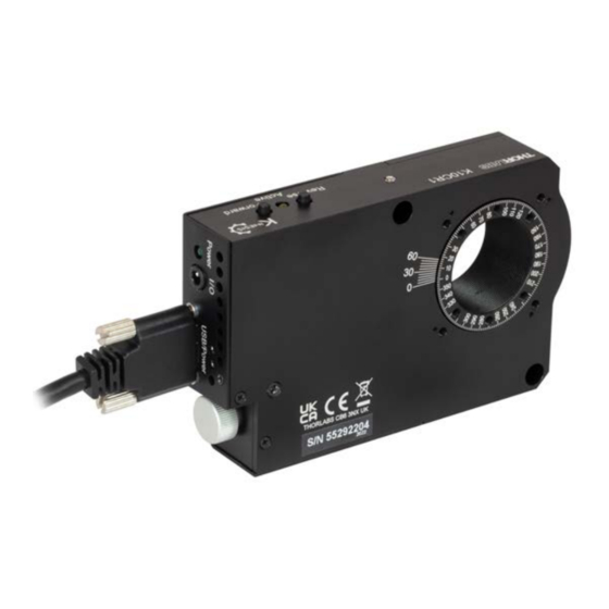
Chapter 4 4.3 Connector Detail The side of the unit is fitted with a number of connectors as shown below:. Fig. 4.1 Power and USB Connectors USB/Power - Provides connection to the PC USB port or the USB hub. Although the port is designed to mate with a USB 3.0 connector, it can also be used with a ‘USB Micro B’... -
Page 15: Verifying Software Operation
K10CR1 Cage Rotation Stage 4) Wait for the unit to initialize (about 5 sec). Do not press any controls during this time. The ENABLE LED is lit when the unit is ready for use. 5) Windows should detect the new hardware. Wait while Windows installs the drivers for the new hardware. -
Page 16: Chapter 5 Operation
The unit is shipped with a set of default parameters already loaded, and can be operated via the buttons on the top face of the unit. Fig. 5.1 K10CR1 Buttons and LEDs Active LED - Yellow LED, lit when the stage is in motion. Flashes when the Ident button on the GUI panel is clicked - see Section 4.5.1.. -
Page 17: Using The Kinesis Software
All basic operating parameters can be set through this program, and all basic operations (such as motor moves) can be initiated. Parameter settings can be saved, which simplifies system set up whenever the software is run up. 1) Run the Kinesis software - Start/All Programs/Thorlabs/Kinesis/Kinesis. Fig. 5.2 K10CR1 Stage Software GUI... -
Page 18: Homing Motors
The limit switch provides a fixed datum that can be found after the system has been powered up. Fig. 5.3 K10CR1 Stage GUI 1) Click the ‘Home’ button. Notice that the ‘Not Homed’ LED changes to ‘Homed’, and that the LED flashes to indicate that homing is in progress. -
Page 19: Changing Motor Parameters And Moving To An Absolute Position
K10CR1 Cage Rotation Stage 5.6 Changing Motor Parameters and Moving to an Absolute Position Absolute moves are measured in real world units (e.g. millimetres), relative to the Home position. Moves are performed using a trapezoidal velocity profile (see Appendix B , Section B.1.3.). -
Page 20: Jogging
Chapter 5 5.7 Jogging During PC operation, the motor actuators are jogged using the GUI panel arrow keys. There are two jogging modes available, ‘Single Step’ and ‘Continuous’. In ‘Single Step’ mode, the motor moves by the step size specified in the Step Distance parameter. -
Page 21: Setting Move Sequences
K10CR1 Cage Rotation Stage 5.8 Setting Move Sequences The Kinesis software allows move sequences to be programmed, allowing several positions to be visited without user intervention. For more details and instructions on setting move sequences, please see the Kinesis Helpfile. -
Page 22: Chapter 6 Software Reference
6.2 GUI Panel The following screen shot shows the graphical user interface (GUI) displayed when accessing the stage using the Kinesis software. Fig. 6.1 K10CR1 Stage Software GUI Note The serial number of the stage associated with the GUI panel is displayed in the top right hand corner. - Page 23 K10CR1 Cage Rotation Stage Velocity Parameters - the present setting for the move velocity parameters and the jog step size. The travel range of the associated stage/actuator is also displayed. These settings can be adjusted as described previously, or by clicking the Settings button to display the settings window, see Section 6.3.2.
- Page 24 Chapter 6 Home - sends the motor to its 'Home' position - see Appendix B Section B.2.2. Stop - halts the movement of the motor. Lower Display - Shows the present state of the motor, e.g. Idle, Moving, Moving EXT or Homing. Also shows the part number of the associated actuator or stage.
-
Page 25: Settings Panel
(refer to the Kinesis Server helpfile for further details. 6.3.1 Persisting Settings to Hardware Many of the parameters that can be set for the K10CR1 stage can be stored (persisted) within the unit itself, such that when the unit is next powered up these settings are applied automatically. - Page 26 Chapter 6 6.3.2 Moves/Jogs Tab Fig. 6.2 Move/Jog Settings Display Units By default, the unit will display position in real world units (degrees). If required, the units can be changed to so that the display shows other positional units (rad, mrad, µrad).
- Page 27 K10CR1 Cage Rotation Stage There are two jogging modes available, ‘Jog’ and ‘Continuous’. In ‘Jog’ mode, the motor moves by the distance specified in the Step Size parameter. If the jog key is held down, single step jogging is repeated until the button is released - see Fig. 6.3.
- Page 28 Chapter 6 Acceleration - the rate at which the velocity climbs from zero to maximum, and slows from maximum to zero. Note Under certain velocity parameter and move distance conditions, the maximum velocity may never be reached (i.e. the move comprises an acceleration and deceleration phase only).
- Page 29 K10CR1 Cage Rotation Stage is decelerated at ‘a’ so that the final position is approached slowly in a controlled manner. velocity maximum velocity (v) acceleration (slope) a time Fig. 6.4 Graph of a trapezoidal velocity profile The S-curve profile is a trapezoidal curve with an additional 'Bow Value' parameter, which limits the rate of change of acceleration and smooths out the contours of the motion profile.
- Page 30 Chapter 6 manner to the acceleration phase, using the Bow Index to reach the maximum deceleration (D) and then bring the axis to a stop at the destination. Note The higher the Bow Index, then the shorter the BI phases of the curve, and the steeper the acceleration and deceleration phases.
- Page 31 They need to be set accordingly such that the stage is driven properly by the system. For K10CR1 stages, the server will automatically apply suitable defaults for the parameters on this tab during boot up of the software. These parameters should not be altered subsequently, as this may adversely affect the performance of the stage.
- Page 32 Chapter 6 Homing Settings When homing, a stage typically moves in the reverse direction, (i.e. towards the reverse limit switch). The following settings allow support for stages with both Forward and Reverse limits. Note Typically, the following two parameters are set the same, i.e. both Clockwise or both Counter Clockwise.
- Page 33 Fig. 6.8 Advanced Settings Power Settings The K10CR1 stage is designed to vary the phase powers (current) in the motor coils depending on the operating state of the motor - moving or stationary. Typically, when a stepper motor is at rest it is advisable to reduce the phase (holding) currents so that the motor does not overheat.
- Page 34 Chapter 6 Move To: In this mode, each button can be programmed with a different position value, such that the controller will move the motor to that position when the specific button is pressed. Note The following parameters are applicable only if ‘Move To’ is selected in the ‘Mode’...
- Page 35 Fig. 6.9 Stepper Driver K-Cube - Triggering Settings Triggering Introduction The K10CR1 controller has a bidirectional trigger port (IO) that can be used to read an external logic signal and output a logic level to control external equipment. Either of them can be independently configured as an input or an output and the active logic state can be selected High or Low to suit the requirements of the application.
- Page 36 Input Trigger Modes When configured as an input, the IO port can be used for triggering a relative, absolute or home move. When used for triggering a move, the port is edge sensitive. In other words, it has to see a transition from the inactive to the active logic state (Low- >High or High->Low) for the trigger input to be recognized.
-
Page 37: Appendix A Specifications
K10CR1 Cage Rotation Stage Appendix A Specifications A.1 Stage Specifications Parameter Value Travel Range 360° Continuous Max Speed 10 °/s Min Speed 0.005 °/s Max Acceleration 20° /s/s *Note The acceleration is limited by the motor force, and must be reduced for higher loads. - Page 38 A.2 Design Specification Parameter Value Base Material Aluminum Bearing Type 4-point Ball Bearing Drive Mechanism Worm Gear, Ratio 1:120 Homing Limit Switch Hall Effect Central Aperture SM1 Threaded Operating Temperature Range 5 to 40°C (41 to 104°F) Motor Type 2-Phase Stepper Motor Motor Drive Voltage 8 V Nominal Terminal Resistance...
- Page 39 K10CR1 Cage Rotation Stage A.3 Load Capacity Specifications Parameter Value Max Load (Q) 22 N (2.25 kg or 5.0 lbs) Max Torque (Mz) 140 mNm 1.5 Nm Max Transversal Torque (Mx) Typical Stiffness (Ka) 380 µrad/Nm Fig. A.1 Load Capacity Definitions...
-
Page 40: Appendix B Stepper Motor Operation
B.1 How A Stepper Motor Works B.1.1 General Principle Thorlabs’ actuators use a stepper motor to drive a precision lead screw. Stepper motors operate using the principle of magnetic attraction and repulsion to convert digital pulses into mechanical shaft rotation. The amount of rotation achieved is directly proportional to the number of input pulses generated and the speed is proportional to the frequency of these pulses. - Page 41 K10CR1 Cage Rotation Stage B.1.2 Positive and Negative Moves Positive and negative are used to describe the direction of a move. A positive move means a move from a smaller absolute position to a larger one, a negative move means the opposite.
- Page 42 Appendix B The S-curve profile is a trapezoidal curve with an additional 'Bow Value' parameter, which limits the rate of change of acceleration and smooths out the contours of the motion profile. The Bow Value is specified in degrees/s and is derived from the Bow Index field as follows: The Bow Value is applied in degrees/s and is derived from the Bow Index field as...
- Page 43 K10CR1 Cage Rotation Stage B.2 Positioning a Stage B.2.1 General Whenever a command is received to move a stage, the movement is specified in motion units, (e.g. millimetres). This motion unit value is converted to microsteps before it is sent to the stage. If operating the unit by the front panel (local mode) this conversion is performed internally by the controller.
- Page 44 Movement is allowed right through the switch position in either direction. Datum switch +ve limit switch -ve limit switch (or stop) Linear stage Rotary stage Fig. B.4 Stage limit switches B.2.4 Power Saving The current needed to hold a motor in a fixed position is much smaller than the current needed to move it, and it is advantageous to reduce the current through a stationary motor in order to reduce heating.
- Page 45 K10CR1 Cage Rotation Stage B.3 Error Correction B.3.1 Backlash correction The term backlash refers to the tendency of the stage to reach a different position depending on the direction of approach. Backlash can be overcome by always making the last portion of a move in the same direction, conventionally the positive direction.
-
Page 46: Appendix C Regulatory
Appendix C Appendix C Regulatory C.1 Declarations Of Conformity C.1.1 For Customers in Europe See Section C.2. C.1.2 For Customers In The USA This equipment has been tested and found to comply with the limits for a Class A digital device, persuant to part 15 of the FCC rules. These limits are designed to provide reasonable protection against harmful interference when the equipment is operated in a commercial environment. - Page 47 K10CR1 Cage Rotation Stage C.2 CE Certificates...
- Page 48 "End of life" units must be returned to Thorlabs or handed to a company specializing in waste recovery. Do not dispose of the unit in a litter bin or at a public waste disposal site.
- Page 49 www.thorlabs.com...
Need help?
Do you have a question about the K10CR1 and is the answer not in the manual?
Questions and answers