Risco WiComm Pro Installation Manual
Hide thumbs
Also See for WiComm Pro:
- Quick user manual (9 pages) ,
- Quick user manual (8 pages) ,
- Quick installation manual (32 pages)
Table of Contents
Advertisement
Quick Links
Advertisement
Table of Contents

Related Manuals for Risco WiComm Pro


Summary of Contents for Risco WiComm Pro
- Page 1 WiComm Pro Model: RW332M Installation Manual...
- Page 2 This guide contains proprietary information belonging to RISCO Group. Such information is supplied solely for the purpose of assisting authorized WiComm Pro system installers. No part of this document or its contents may be used for any other purpose, disclosed to any person or firm, or reproduced in any form whatsoever, without the express prior written permission of RISCO Group.
-
Page 3: Table Of Contents
Main Panel LEDs......................12 Communication Modules .................... 13 GSM/GPRS........................13 IP ..........................13 Wi-Fi ..........................14 Installing Communication Modules ................15 CHAPTER 4: INSTALLING THE WICOMM PRO ..............16 ....................16 NSTALLING THE ANEL Mounting Guidelines ....................16 Wall-Mounting the Main Panel................... 16 CHAPTER 5: INSTALLER PROGRAMMING .............. - Page 4 Clearing Device Allocation ..................27 Clearing a Device Allocation from the Installer Keypad ............27 Clearing a Device Allocation with the Configuration Software ..........27 Clearing All System Device Allocations with the Configuration Software ......27 RISCO C ............. 28 STABLISHING OMMUNICATION TO THE...
- Page 5 Keypads ..........................71 Parameters ........................71 Controls ......................... 72 Sirens ..........................73 I/O Wireless Expander ....................... 74 Wired Zones ........................74 Output Parameters ......................76 X-10 Outputs ......................... 81 Parameters ........................81 Identification ......................... 82 Codes ........................... 83 User ............................83 Codes: User Codes .........................
- Page 6 INSTALLER EVENT LOG MESSAGES ..........123 APPENDIX C: REMOTE FIRMWARE UPGRADE ............128 APPENDIX D: INSTALLER PROGRAMMING MAPS ..........133 APPENDIX E: WICOMM PRO CERTITICATIONS ............143 EN 50131 & EN 50136 C ................. 143 OMPLIANCE SIA CP-01 C ....................146...
-
Page 7: Chapter 1: Introduction
Chapter 1: Introduction The WiComm Pro wireless security alarm system is ideal for installation in any home or small business environment. It supports RISCO’s extensive range of wireless security and safety devices, detectors, keypads, remote controls, key fobs, wireless sirens and other peripheral accessories. -
Page 8: Robust And Full-Featured System
Robust and Full-Featured System Detectors / Monitoring Station Communication Installer Programming & Visual Verification Device Allocation • Remote programming, • Flexible communication • Using up to 8 PIR • Local / remote diagnostics, and over GSM/GPRS, IP detector / cameras – also programming using •... -
Page 9: Wicomm Pro Architecture
Remote system programming and maintenance Owner remote control Cloud Communication Wicomm Pro can be constantly connected to a dedicated application server (the “RISCO Cloud”) via IP or GPRS. The RISCO Cloud handles all communication between the WiComm Pro system, monitoring stations and Smartphone/Web users, enabling remote monitoring and control, as well as a RISCO’s VUpoint video verification solution that utilizes IP cameras:... -
Page 10: Back-Up Communication
Cloud) or directly from the WiComm Pro system to the monitoring station using the RISCO IP Receiver. Events can be reported in SIA/IP, SIA and Contact ID monitoring protocols. In addition, WiComm Pro can send events in SIA IP protocol over TCP/IP to monitoring stations that have standard IP receivers. -
Page 11: Configuration Software
Powered by the RISCO Cloud, VUpoint enables the initiation of live video streaming on demand from any IP camera which can be viewed directly using the iRISCO smartphone or Web applications. -
Page 12: Product Specification
Product Specification Configuration Maximum number of partitions Maximum number of wireless zones Maximum rolling-code remote controls / key fobs Maximum wireless 2-way slim keypads Maximum Follow Me numbers Maximum user codes Grand Master, Installer, and Sub-Installer codes 1 each Maximum events in event log 1000 Maximum alarm sounders (internal/external) Electrical... -
Page 13: Safety Precautions
• 868.65 MHz, 10mW; 869.525 MHz, 100mW Max Power Output IP Module (RP512IP) • Current consumption Average: 60 mA; Peak: 115 mA Wi-Fi Module (RP51200W) • Current consumption Average: 60 mA; Peak: 115 mA Safety Precautions WARNING: Installation or usage of this product that is not in accordance with the intended use as defined by the supplier and as described in the instructional materials can result in damage, injury or death. -
Page 14: Chapter 2: Typical System Components
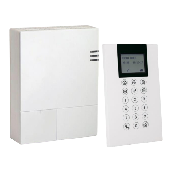
Chapter 2: Typical System Components Main panel Plug in Communication Modules: Single / Multi channels IP or GPRS Wireless 2-way Keypads Remote control (key fob). 1-way and 2-way models available Magnetic door/window contact (includes sensor and magnet) PIR motion detector (with or without camera). - Page 15 Safety detectors: Smoke, Wireless Flood Detector and Sensor Wireless acoustic Glass Break Detector Indoor Wireless Sounder VUpoint IP Cameras: Page 9...
-
Page 16: Chapter 3: Describing And Using The Main Panel
Chapter 3: Describing and Using the Main Panel WiComm Pro Main Components Front access cover LED indicators Locking-screws (2) Back tamper screw location Wiring channel for network cable (shown with cable routed via hook) ... - Page 17 Enables loading local software updates to the PRGM: WiComm Pro. • ON: software updates to the WiComm Pro can be loaded • OFF (Default): software updates to the WiComm Pro cannot be loaded Default jumper: Used when performing the following:...
-
Page 18: Main Panel Leds
Main Panel LEDs Color State Status Green Powered on Upper LED Electrical power supply trouble (Power) Orange Low battery System armed (Full Arm or Partial Arm modes) Rapid Alarm activation flash Slow System is in entry/exit delay before disarming/arming the system flash Middle LED (Status) -
Page 19: Communication Modules
SMS, and e-mail (in parallel to the Cloud-based notifications), depending on system configuration. Reporting events to monitoring stations is via GPRS or SMS (using the RISCO IP Receiver). Events can be reported in SIA, SIA IP, and Contact ID monitoring protocols. -
Page 20: Wi-Fi
Wi-Fi To Connect with Wi-Fi Note: Your Router’s Wi-Fi must be activated for the Control Panel to recognize and communicate with the Router. To connect via Wi-Fi network, you must select your Router’s Wi-Fi network. Go to Activities –> Wi-Fi screen: available networks appear in a list. Select the desired network and enter the password (if required). -
Page 21: Installing Communication Modules
Installing Communication Modules Plug in IP Module Plug in GSM Module (front and back) (front and back) SIM holder on GSM module Antenna for GSM module (shown with internal antenna installed) GSM module ... -
Page 22: Chapter 4: Installing The Wicomm Pro
Installing the WiComm Pro Installing the Main Panel IMPORTANT: Only alarm system installers or similar professionals (such as electricians) should install and service the WiComm Pro Mounting Guidelines Install the main panel in consideration of the following guidelines: • Install in a centrally-located place, between all the wireless devices in your system, for optimal communication •... - Page 23 Disconnect the mounting bracket (back cover of main panel) by releasing the two locking screws at the base of the unit, and then lifting the unit upward to detach the two tabs from the respective grooves on the mounting bracket: ...
- Page 24 Plug in the communication modules IP Module: If your WiComm Pro is equipped with an IP card Install the IP communication module in its cavity (back cover), with its connector fitting securely onto its respective socket.
-
Page 25: Chapter 5: Installer Programming
• Via Customer’s Wireless Panda (2-Way LCD + Proximity) keypad Configuration Software The Configuration Software enables you to program the WiComm Pro from a computer. It enables the following: • Working locally with a portable computer physically connected to the WiComm Pro via RS 232 cable •... - Page 26 To (temporarily) allocate the installer keypad and define the system language: After the main panel is connected to the power supply, short-press the LEARN button; AC Power Connection DC Power Connection With battery installed, press the Panda/LCD keypad’s buttons simultaneously during the status announcement until the following message appears: Select Language: Using the arrows scroll the options and press the selected language.
-
Page 27: Allocating The Customer's Panda/Lcd Keypad
Allocating the Customer’s Panda/LCD Keypad WiComm Pro can be fully configured via the customer’s wireless Panda/LCD keypad. New systems require that the LCD keypad be the first device to be allocated to the system, from which it then prompts the installer to define a default language. After the Panda/LCD... -
Page 28: Wireless Device Allocation Options
Use the buttons to scroll between the following Programming menu items (“sub-menus”): • 1) System • 2) Radio Devices • 3) Codes • 4) Communication • 0) Exit To exit the Programming sub-menus, press zero (0). Wireless Device Allocation Options All wireless devices (detectors and accessories) must also be allocated (“enrolled”) to the system. -
Page 29: Quick Device Allocation At The Main Panel
Quick Device Allocation at the Main Panel You can quickly allocate all system devices at the main panel. NOTE: For quick allocation at the main panel, the system bit Quick Learn must be enabled. ➢ To quickly allocate all wireless devices at the main panel: Make sure batteries are installed in each device. -
Page 30: Wireless Device Rf Transmissions
Wireless Device RF Transmissions Wireless Device Transmission procedure 2-Way LCD Keypad Press simultaneously for at least 2 seconds 2-Way Panda Keypad Press simultaneously for at least 2 seconds. 2-Way Slim Keypad Press simultaneously for at least 2 seconds. PIR Detectors: •... -
Page 31: Device Allocation Using The Wireless Lcd Keypad
Device Allocation using the Wireless LCD Keypad RF Allocation Method Using the RF Allocation method, zones are assigned automatically and sequentially. To perform device allocation by RF Allocation: Go to the Installer menu and select Programming → Radio Device → Allocation → 1) RF Allocation. -
Page 32: Allocating Devices With The Configuration Software
Allocating Devices with the Configuration Software The installer can perform wireless device allocation via the system Configuration Software by either RF allocation, or by entering the device’s code (serial number). RF Allocation To allocate a device by RF allocation: Establish communication between the main panel and the Configuration Software. For more information refer to the documentation for the Configuration Software. -
Page 33: Clearing Device Allocation
Select the wireless device’s index number. Selecting “Automatic” means that the index number will be automatically assigned by the system. Click ; the main panel acknowledges the transmission with a beep, and the Radio Device Allocation screen indicates the allocation status as “successful.” Clearing Device Allocation Clearing a device’s allocation (deleting a wireless device) can be done either from the installer keypad or from the Configuration Software. -
Page 34: Establishing Communication To The Risco Cloud
Establishing Communication to the RISCO Cloud WiComm Pro can be configured to be constantly connected to the RISCO Cloud, an application server that handles all communication between the system, service providers and Smartphone/Web users. The Cloud enables remote monitoring and control of the system, sending event notifications, and viewing real-time video clips via VUpoint IP cameras –... -
Page 35: Irisco App
Once the self-registration is complete, users can enjoy the iRISCO Smartphone app for smart and easy control of their WiComm Pro system from any location. The next step is to download the iRISCO app from the Apple App store or Android Play Store... -
Page 36: Chapter 6: Programming The Installer Menus
Chapter 6: Programming the Installer Menus The installer menus and nested entities (sub-menus, options and parameters) are programmed by the installer using the installer keypad or the Configuration Software (refer to the Configuration Software documentation). Describing Installer Keypad Buttons The following buttons are commonly used for programming (the buttons shown are for the 2-Way Wireless Panda LCD &... -
Page 37: Programming Menu
NOTE: If the Authorize Installer system bit is defined as YES, a Grand Master code is required to authorize the installer to enter the programming mode. In this case the Grand Master code should be entered after the installer code via the Grand Master menu >... -
Page 38: Timers
Timers The Timers option has the following parameters: System: Timers Parameter Default Range Exit/Entry Delay 1 The amount of time before the system is armed/disarmed. Usually used on front entrance door. Entry Delay 1 45 sec 0-255 sec Duration of entry delay 1 before the system is disarmed. Exit Delay 1 45 sec 0-255 sec... - Page 39 System: Timers Parameter Default Range Specifies how often the system expects to get a signal from the system's transmitters. If a signal from a zone is not received during the specified time the zone will be regarded as “lost,” the system will send a report code to the monitoring station, and the system status will be "Not Ready".
-
Page 40: Controls
System: Timers Parameter Default Range Entry Bypass 45 seconds (15–240) When the Wireless 2-Way Slim Keypad reader is defined as bypass mode, this timer defines the period during which an Open Delay Zone Type (typically a door) can be opened without triggering an alarm event. Service Time 20 minutes 0-240 minutes... - Page 41 System: Controls Parameter Default Siren Squawk YES: Arming or disarming the system using a remote control, wireless keypad or a key fob produces a brief "chirp" and activates the strobe as follows: • One chirp indicates the system is armed (also when arming with a keypad) •...
- Page 42 System: Controls Parameter Default Arm Pre-warning Related to auto Arm/Disarm operation. YES: For any partition(s) set up for Auto Arming, an audible Exit Delay (warning) countdown will commence 4.25 minutes prior to the automatic arming. During this period, Exit Delay beeps will be heard. You can enter a valid user code at any time during the countdown to delay the partition's automatic arming by 45 minutes.
- Page 43 System: Controls Parameter Default Advanced programming Area Changes the system operation to Area instead of Partition, which then changes only the operation of a common zone. YES: When selected, the following points are relevant: • A common zone will be armed after any partition is armed •...
- Page 44 System: Controls Parameter Default Technician Reset YES: It is necessary to enter the installer code to reset an armed partition after it has been disarmed. This requires the intervention of the alarm company. Note: Before the “ready” LED can light, all zones within the partition must be secured. NO: Once an armed partition is reset, the “ready”...
- Page 45 System: Controls Parameter Default NO: Causes the following parameters to function as follows: • Auto Arm Bypass: If the Auto Arm programming arms the system and there is an open zone during the Auto Arm, the system will bypass the open zones and arm the system •...
- Page 46 Follow Me phones. NO: Disables Follow-Me communication. Cloud Enable Yes: Enables communication between the WiComm Pro system and the RISCO Cloud server. NO: Does not enable communication, as detailed above.
- Page 47 System: Controls Parameter Default Restore Alarm YES: The user must confirm that he/she is aware that alarm occurred in the system before rearming the system. The system will be in "Not Ready" status until the user confirms the alarm. This is done via the User menu > Activities > Advanced > Restore Alarm.
- Page 48 System: Controls Parameter Default Attenuation YES: The WiComm Pro receiver will be attenuated by 6 dB during the communication test. NO: The WiComm Pro receiver works in normal operation mode. DD243 programming Bypass Exit/Entry YES: It is possible for the user to bypass an Exit/Entry zone.
- Page 49 System: Controls Parameter Default Entry Disarm Determines if the system’s disarming depends on the entry time. YES: A remote control or keypad proximity tag can disarm the system during the entry time. Note: The system cannot be disarmed with a remote control while the system is armed. This parameter setting is relevant only for the Away Arm (Full Arm) state and not for Stay Arm (Partial Arm).
-
Page 50: Labels
System: Controls Parameter Default 3 Minute Bypass YES: Bypasses all zones automatically for 3 minutes when power is restored to an "unpowered" system. NO: No bypassing occurs. Labels You can rename the labels that identify the system and partitions by changing the default labels (Partition 1, Partition 2, etc.) to meaningful names / location descriptions, for example, “Sales Dept,”... -
Page 51: Sounds
Sounds Sounds contains parameters that enable you to set the sound(s) that will be produced by the system after the following system events: System: Sounds Parameter Default Range Tamper Sound BELL/A Sil/D 1 to 6 Sets the sound(s) produced by a tamper violation according to the following options: •... -
Page 52: System Settings
Customer ID results in changing the system language and default settings according to the predefined factory Customer ID settings. Use this setting to alter the Customer ID specified upon first-time WiComm Pro start-up. Consult with your RISCO representative to acquire the appropriate Customer ID. -
Page 53: Service Information
Service Information Service Information enables you to insert information accessible to the system's users of the alarm company from where the service is obtained. System: Service Information Parameter Default Range Name Kontakt G4S Any 16 characters Enables you to insert and/or edit the name of the alarm company from where service may be obtained. -
Page 54: Picture Server
Picture Server Picture Server enables you to define a server on which to store and access images captured by system cameras. Use this feature for the http solution Web application and smartphone users. System: Picture Server Parameter Default Range Server IP Enter the IP address of the router/gateway of the server where the pictures are to be located. -
Page 55: Radio Devices
System: Picture Server Parameter Default Range Image Channel Choose here the image transmitting channel for the http server, subject to the system’s installed networks. This feature requires that the monitoring station receiver supports the SIA IP Note: protocol The four options are: •... -
Page 56: Zones
4. Sirens 5. I/O Expanders NOTE: This list varies according to the devices that have been allocated to the system. Only devices that have been allocated can be configured or modified by the installer. Zones The Zones category has the following: •... - Page 57 Zones: Parameters Parameter Default Range Exit/Entry 2 Same as above, except that the Exit/Entry 2-time period applies. Exit(Op)/Entry 1 Used for an Exit/Entry door. This zone behaves as described in the Exit/Entry 1 parameter, shown above, except that, if faulted, the arming process is not prevented.
- Page 58 Zones: Parameters Parameter Default Range Interior + Exit(Op)/Entry 1 Used for an exit/entry door that, for convenience, may be kept open when the system is being armed, as follows: ⬧ In Away (Full Arm) mode behaves as an Exit (Op)/Entry 1 zone ⬧...
- Page 59 Zones: Parameters Parameter Default Range Panic Used for external panic buttons and wireless panic transmitters. If violated, an immediate panic alarm is sounded (if the zone sound is not defined as silent or the Audible Panic system control is enabled), regardless of the system's state –...
- Page 60 Zones: Parameters Parameter Default Range Technical This zone operates the same as 24 hours zone, but its report code should be manually set according to the relevant detector connected to the zone. Final Exit Zones of this type must be for the last detector to be activated upon exit or the first detector to be activated upon entry.
- Page 61 Zones: Parameters Parameter Default Range Pulsed Key Switch Connect an external momentary-action key switch to any zone given this designation. This zone will arm/disarm the partitions assigned to it. Pulsed Key Switch Delayed Used to apply the Exit/Entry Delay 1 parameter to the Pulsed Key Switch zone.
- Page 62 Keybox (Designed for the Danish market) A keybox is defined as a physical container in which to place the house keys. The WiComm Pro keybox zone behaves as follows: ⬧ Opening a key box zone (regardless of system arming status) sends a message to the monitoring station and recorded in the event log ⬧...
- Page 63 Zones: Parameters Parameter Default Range Bell/Arm Buzzer/Disarm In a case of alarm, the following occurs: ⬧ In Away mode (Full Arm) the wireless siren will operate ⬧ In Disarm mode, only the buzzer on the main panel will operate Advanced programming Chime None The Chime parameter is used as an audible indication to a zone violation while the...
- Page 64 1) Enable or 2) Disable sending a push notification to the end-user. Note: The Presence push notifications option must also be selected in the RISCO Cloud for the notifications to be sent to the end-user’s smartphone. he Presence zone can also be muted via the RISCO Cloud.
- Page 65 RWX73M and RWX73F. The programming options RWX73 M Parameters The RWX73M is a 2-way supervised transmitter that combines Magnetic/Door contact against opening doors and windows with additional universal input. The RWX73M operates with RISCO Group 2-Way wireless systems Magnet Enable Enable/Disable Enable or disable the transmitter’s magnet.
- Page 66 Magnetic/Door contact (universal or shutter). The RWX73F has two reed switches for protection against opening doors and windows, and against any attempt to tamper the detector using large magnets. The RWX73F operates with RISCO Group 2-Way wireless systems Alarm Hold On/Off Use this parameter to define the minimum period between alarm broadcasts.
- Page 67 Magnetic/Door contact (universal). The RWX73F has two reed switches for protection against opening doors and windows, and against any attempt to tamper the detector using large magnets. The RWX73F operates with RISCO Group 2-Way wireless systems Magnet Enable Enable/Disable Enable or disable the transmitter’s magnet.
- Page 68 RWX78M Parameters (2 way Slim Contact detectors) On/Off Defines the LED operation mode. On: Detector's LED activated Off: Detector's LED deactivated Hold On On/Off Use this parameter to define the minimum period between alarm transmissions. ON: Only one alarm message is transmitted in any 2.5-minute time-period OFF: Alarm detection is immediately transmitted.
- Page 69 Defines the detector’s level of sensitivity. RWX78SM Detector Parameters (for 2 way Slim Shock and Contact detectors) RWX78MU Detector Parameters (for 2 way Magnetic Contact and Universal detectors) Magnet LED Enabled Yes/No Defines the LED operation mode. Yes: Detector's LED activated No: Detector's LED deactivated Hold On On/Off...
- Page 70 RWX78SMU Detector Parameters (for 2 way Magnetic Contact, Shock and Universal detectors) Magnet LED Enabled Yes/No Defines the LED operation mode. Yes: Detector's LED activated No: Detector's LED deactivated Hold On On/Off Use this parameter to define the minimum period between alarm transmissions.
- Page 71 Use this parameter to define the minimum period between alarm transmissions (not applicable for shutter termination). ON: Only one alarm message is transmitted in any 2.5-minute time-period OFF: Alarm detection is immediately transmitted. Pulses number 2/4/6/8/10/12/14/16 Defines the pulse number threshold for shutter input. Input Protection On/Off Defines whether to generate a tamper message due to input wires shorted...
-
Page 72: Alarm Confirmation
Input Protection On/Off Defines whether to generate a tamper message due to input wires shorted (applicable for shutter only). Alarm Confirmation Alarm Confirmation enables to define protection against false alarms and will be used for alarm verification. Zones: Alarm Confirmation Parameter Default Range... -
Page 73: Zone Crossing
Correlation Type Determine how the WiComm Pro will process violations of the paired zones. • Not correlate: Temporarily disables any associated zone pairings • Ordered correlate: Effects an alarm so the first listed zone is tripped before the second •... -
Page 74: Remote Controls / Key Fobs
Remote Controls / Key Fobs Remote Controls / Key Fobs defines the operation of the remote controls / key fobs. Up to 8 remote controls / key fobs can be assigned to the system. The system supports 2 types: • One-way (one-directional) key fobs (4-button model) •... -
Page 75: Wireless Two-Way Remote Control Parameters
Remote Control Parameters – 1-Way Key Fob Parameter Button 4 Set the operation of button 4 (Large blank button) of the key fob from the following options: • None: Button disable • Arm: The button is used for Away (Full) arming of the key fob‘s partitions •... -
Page 76: Controls
UO Key 1/2/3 Each remote control can activate up to 3 outputs. Assign to each of the keys 1-3 the relevant output. Controls Controls are relevant for both types of remote controls / key fobs. Remote Controls / Key Fobs – Controls Control Instant Arm YES: Away arming (Full arming) from any remote control will be instant. -
Page 77: Keypads
Keypads The system can support up to 3 wireless keypads. The types supported are the Wireless LCD keypad (for installer only), and the Wireless 2-Way Slim Keypad (both indoor and outdoor models). For detailed information regarding the operation of the keypads refer to the instructions supplied with the product. -
Page 78: Controls
UO Control Assign outputs that will be activated by a long press on keys on the bidirectional keypad. Notes: Outputs can be assigned only if I/O is assigned to the system. Each keypad can activate different outputs. Only outputs defined as Follow Code can be activated by the keypad keys Mode (for the Wireless 2-Way Slim Keypad only) Use this parameter to define the wireless 2-way slim keypad operation mode. -
Page 79: Sirens
Sirens Sirens enables defining all parameters of external and internal wireless sirens that can be connected to the system. Up to 3 sirens can be added to the system. For detailed information regarding the operation of the sirens refer to the instructions supplied with the product. -
Page 80: I/O Wireless Expander
Wireless Device: Sirens Parameter Default Range Strobe Blink Defines the number of times that the strobe will blink in a minute: • 20 times per minute • 30 times per minute • 40 times per minute • 50 times per minute •... - Page 81 I/O Expander: Wired Zones Parameter Default Range Define whether the zone can be force armed or not. For more information refer to page 57. No Activity Determines whether the zone participates in the No Activity function. The No Activity function is for reception of signals used to monitor the activity of sick, elderly or disabled people.
-
Page 82: Output Parameters
I/O Expander: Wired Zones Parameter Default Range Detection Mode • Normal (Default): 2.5 minutes dead time between alarm detections transmissions • Fast (Walk Test): Alarm detection is immediately transmitted Output Parameters The I/O Expander has 4 physical outputs on board: 2 relays (3 amp), and 2 transistor outputs (500 mA) I/O Expander: Output Parameters Parameter... - Page 83 I/O Expander: Output Parameters Parameter Default Range AC Loss Activates when the source of the Main Panel's AC power is interrupted. This activation will follow the delay time defined in the system control times and the AC Off Delay Time parameter. Bell burglary Activates the Utility Output after any bell burglary alarm in any partition in the system.
- Page 84 I/O Expander: Output Parameters Parameter Default Range Activates the utility output when all the selected partition(s) are in the Ready state. Activates the utility output when the selected partition(s) is armed in Away (Full Arm) mode. The utility output will be activated immediately, regardless of the Exit Delay time period.
- Page 85 I/O Expander: Output Parameters Parameter Default Range Zone Lost Activates the utility output when there is a lost wireless zone in the system. The output restore shall be on Bell-Timeout or at user Disarm. Stay Follow Activates the utility output Utility Output when the selected partition(s) is armed in Stay mode.
- Page 86 I/O Expander: Output Parameters Parameter Default Range Disarm Activates the utility output when the selected zones are disarmed. Follow User Code: Defines the User Code(s) for triggering the selected utility output (UO). The activation of the UOUO is performed from the User Activities menu. Use the key to toggle between [Y] YES or [N] NO for each user chosen to trip the designated Utility Output.
-
Page 87: X-10 Outputs
I/O Expander: Output Parameters Parameter Default Range Activation / Deactivation When the utility output is following more than one partition or zone, the installer can choose the logic of the utility output Utility Output activation as follows: • If the pattern operation of the output is defined as Latch N/O or Latch N/C, the activation and deactivation of the outputs can follow either after all the Partitions/Zones zones or after any of the Partitionspartitions/Zoneszones. -
Page 88: Identification
Defines the house code, which matches the code defined by the X-10 modules. UO DTMF Control The WiComm Pro enables to activate 8 utility outputs from remote DTMF phone. To operate a UO via the telephone you must assign a specific UO to a digit on the phone. -
Page 89: Codes
Codes The Codes sub-menu enables defining parameters and codes for system users. User User rights can be defined by allocating each user a specific authority level and specific partitions. Up to 32 users can be defined in the system. Codes: User Codes Parameter Default Labels... -
Page 90: Grand Master
Installer The installer code provides access to the installer Programming menu, allowing modification of all system parameters. The installer Code is used by the WiComm Pro installation company technician to program the system. The installer can change the installer code (default is 1111). -
Page 91: Dtmf Code
3. Configuration Software 4. Follow-Me 5. Cloud Method This option allows you to configure the parameters of the following WiComm Pro communication methods (channels) : 2. GSM 3. IP The GSM screen contains parameters for the communication of the system over the GSM/GPRS network. - Page 92 Method: GSM Parameter Default Range Timers Allows to program timers related to operation with the GSM module GSM Lost 10 min 001-255 min The time after which the GSM module regards the GSM network as loss. Network loss is defined as RSSI level below the level defined GSM Network Sensitivity parameter.
- Page 93 Method: GSM Parameter Default Range GPRS Allows programming parameters that relate for the communication over the GPRS network. Access Point Network (APN) Code internet To establish a connection to the GPRS network an APN (Access Point Name) code is required. The APN code differs from country to country and from one provider to another (the APN code is provided by your cellular provider).
- Page 94 Method: GSM Parameter Default Range Controls Allows to control timers related to operation with the GSM. Caller ID NO/YES The Caller ID function enables to restrict SMS remote control operations to the predefined Follow Me phone numbers. If the incoming number is recognized as one of the Follow Me numbers, the operation will be executed.
- Page 95 Method: GSM Parameter Default Range GSM Network Sensitivity (RSSI) Set the minimum acceptable network signal level (RSSI level). Options: Disabled (No troubles for low signal reception) / Low signal / High signal SIM Number The SIM phone number. The system uses this parameter to receive the time from the GSM network in order to update the system time.
- Page 96 Obtain Automatic IP Dynamic IP Dynamic IP/Static IP Defines whether the IP address, which the WiComm Pro refers to, is static or dynamic. Dynamic IP: The system refers to an IP address provided by the DHCP. Static IP: The system refers to a static IP Address.
- Page 97 If required by the mail server, fill in the Authentication User password Host Name Security_System (Up to 32 characters) IP address or a text name used to identify the WiComm Pro over the network. Default: Security System MS Keep Alive (Polling)
-
Page 98: Monitoring Station
The event messages are received by RISCO Group's IP/GSM Receiver Software located at the MS/ARC site. The IP/GSM Receiver translates the SMS messages to standard protocols used by the monitoring station applications (For example;... - Page 99 Range Encrypted events are sent to the monitoring station over the IP or GPRS network using TCP/IP protocol. 128 BIT AES encryption is used. RISCO Group's IP/GSM Receiver Software located at the MS/ARC site receives the messages and translates them to standard protocols used by the monitoring station applications (For example;...
- Page 100 Communication: Monitoring Station Parameter Default Range Accounts Account Number The number that recognizes the customer at the monitoring station. You can define an account number for each monitoring station. These account numbers are the 6-digit numbers assigned by the Monitoring Station. Notes for Account Number in Contact ID Communication Format: •...
- Page 101 Allows to program control related to operation with the monitoring station. Handshake YES: All LEDs on the WiComm Pro main panel light for one second when the handshake signal is received from the Monitoring Station's receiver. NO: No indication for establishing communication with the Monitoring Station's receiver.
- Page 102 Communication: Monitoring Station Parameter Default Range Alarm Restore Specifies under what conditions an Alarm Restoral is reported. This option informs the Monitoring Station of a change in the specified condition(s) during an alarm restore. These reports need a valid Report Code. ⬧...
- Page 103 Communication: Monitoring Station Parameter Default Range Cancel Delay 5 min 0-255 min If an alarm is sent in error, it is possible for the Monitoring Station to receive a Cancel Alarm Code, sent subsequently to the initial Alarm Code. This happens if a valid User Code is entered to reset the alarm in the Cancel Delay time window that starts after the defined Abort Alarm time is over.
- Page 104 Communication: Monitoring Station Parameter Default Range Report Split The Report Split menu contains parameters that enable the routing of specified events to up to three Monitoring Station Receivers. (See Appendix A – Report Codes) MS Arm/Disarm Reports Arming/Disarming (meaning Closings/Openings) events to the Monitoring Station ⬧...
-
Page 105: Configuration Software
Access Code 5678 Enables you to define an access code that is stored in the system. RISCO Group recommends using a different 4-digit access code for each installation. In order to enable communication between the alarm company and the system... - Page 106 Communication: Configuration software Parameter Default Range Remote ID 0001 Defines an ID Code that serves as an extension of the access code. In order to enable communication between the alarm company and the Installation, the same Remote ID code must be entered into the account profile in the configuration software.
-
Page 107: Follow-Me
The host subnet address (listener port number) Follow-Me In addition to reporting to the monitoring station, the WiComm Pro can notify end users of various system events. Reporting can be done directly from the WiComm Pro to the end user by SMS (up to 16). Reporting can also be by Email or Push Notification from the main unit or using the RISCO Cloud. -
Page 108: Define Follow Me
Define Follow Me Communication: Follow-Me Parameter Default Range Label (via the Configuration Software) A label identifying the follow me destination Report Type Defines the type of reporting events to a Follow Me destination: • Voice: Not Applicable. • SMS: Report to Follow Me will be done by SMS. Each event message contains information including the system label, Event type and time. - Page 109 Parent control feature Troubles False Code After 5 unsuccessful attempts of entering incorrect code. Main Low Battery Low battery indication from the WiComm Pro main panel (below 6V) Wireless Low Low battery indication from any wireless device in the...
- Page 110 Intruder alarm in the system restored Tamper Tamper alarm in the system restored Troubles Main Low Battery Low battery indication from the WiComm Pro main panel restored WL Low Battery Low battery indication from any wireless device in the system restored...
- Page 111 Communication: Follow-Me Parameter Default Range AC Off Interruption in the source of the main AC power restored IP Network Communication trouble in the IP restored GSM Trouble General GSM trouble restored Environmental Gas Alert Gas Alert restored Flood Alert Flood Alert restored CO Alert CO Alert restored High...
-
Page 112: Cloud
Define here the server settings for communication with the WiComm Pro system IP Address 91.221.51.215 The IP address or server name. If the WiComm Pro system is connected to the RISCO Cloud for self-monitoring, then use: riscoCloud.com. Otherwise enter the IP address or name where the Cloud server is located. - Page 113 Yes: Parallel reporting to the Follow Me destination can be established via both the Cloud and non-Cloud channels. No: Communication to the Follow Me destination via the non-Cloud channels can be established only in backup mode (when the WiComm Pro-to-Cloud connection is down) App Arm...
-
Page 114: Testing Menu
Testing Menu The following menu is used to perform tests on the system. Note that each test refers to the last time the device was activated. Tests can be performed on the following: 1. Main Unit 2. Zone 3. Keyfob 4. -
Page 115: Zone
Zone Zone Parameter Comm Test Displays the results of the last measurement performed after the last transmission (last detection or last supervision signal). To receive an updated signal strength, activate the detector prior to performing the communication test. For successful communication, the strength of the signal should be higher than the noise threshold level as measured during calibration of the main panel. -
Page 116: Remote Control
Remote Control Remote Control Parameter Default Range Comm Test Displays the results of the last measurement performed after the last transmission. To receive an updated signal strength, activate the remote control prior to performing the communication test. For successful communication, the strength of the signal should be higher than the noise threshold level as measured during calibration of the main panel. -
Page 117: Siren
Siren Parameter Comm Test The siren communication test performs a communication test between the WiComm Pro and the selected siren. The value displayed indicates the siren's signal strength as received by the WiComm Pro. For successful communication, the strength of the signal should be higher than the noise threshold level as measured during calibration of the main panel. -
Page 118: Gsm
IMEI View the IMEI number of the GSM module. This number is used for identification of the WiComm Pro at the RISCO IP receiver when using GSM or GPRS communication. IP Address The IP address given to the GSM when used in the Listener mode. -
Page 119: Uo Unit
UO Unit UO Unit Parameter Default Range Comm Test Displays the results of the last measurement performed after the last transmission. To receive an updated signal strength, activate the UO unit prior to performing the communication test. For successful communication, the strength of the signal should be higher than the noise threshold level as measured during calibration of the main panel. - Page 120 IP or GPRS. The location of the new firmware should be predefined under Installer Programming> System>Firmware Update. Once the communication method is selected (IP or GPRS) a special manufacturer password should be entered. Please refer to your local RISCO branch for this password. System Restart Enables to restart the main panel via the keypad.
-
Page 121: Follow Me Menu
Activities Parameter Default Range More 1)WiFi 1)Scan Networks: The Control panel scans for Wi-Fi networks and shortly after available networks appear in a list (the connected network is marked and appears first in the list). The rest of the list is sorted from high RSSI to low, with a max. -
Page 122: Event Log Menu
Macro Menu Macro Keys WiComm Pro enables the installer or Grand Master to record a series of commands and assign them to a macro. When the macro is pressed, the recorded commands are executed from beginning to end. Up to 3 macros can be programmed to a system using the LCD/Panda keypad or the WiComm Pro Configuration Software. -
Page 123: Activating A Macro
To program a macro: In the Macro menu select a macro (A, B or C), and then press Enter the sequence of characters according to the following table: Represents Used to enter numerical characters Used to move the curser to the left Used to move the curser to the right Represents the ... -
Page 124: Appendix A: Report Codes
Appendix A: Report Codes Report Codes Parameter Contact ID Report Category Alarms Panic alarm Urgent Panic alarm restore Urgent Fire alarm Urgent Fire alarm restore Urgent Medical alarm Urgent Medical alarm restore Urgent Duress alarm Urgent Duress alarm restore Urgent Box tamper Urgent Box tamper restore... - Page 125 Report Codes Parameter Contact ID Report Category IP Network trouble Non- urgent IP Network trouble restore Non- urgent Arm/Disarm User Arm Arm/Disarm User Disarm Arm/Disarm Stay Arm (Partial Arm) Arm/Disarm Disarm after alarm Arm/Disarm Keyswitch Arm Arm/Disarm Keyswitch Disarm Arm/Disarm Auto Arm Arm/Disarm Auto Disarm...
- Page 126 Report Codes Parameter Contact ID Report Category Water (Flood) alarm Urgent Water (Flood) alarm restore Urgent Gas alarm Urgent Gas alarm restore Urgent Carbon Monoxide alarm Urgent Carbon Monoxide alarm restore Urgent Environmental alarm Urgent Environmental alarm restore Urgent Low Temperature (Freeze alarm) Urgent Low Temperature restore Urgent...
- Page 127 Report Codes Parameter Contact ID Report Category Zone confirm alarm Urgent Zone confirm alarm restore Urgent No activity Urgent No activity restore Urgent Wireless Keypad Tamper Urgent Tamper restore Urgent Low battery Non- urgent Low battery restore Non- urgent Wireless Key Fob Arm/Disarm Disarm Arm/Disarm...
- Page 128 Report Codes Parameter Contact ID Report Category Miscellaneous Enter programming (local) Arm/Disarm Exit programming (Local) LS (LX ) Arm/Disarm Enter programming (Remote) Arm/Disarm Exit programming (Remote) Arm/Disarm MS periodic test Non- urgent MS keep alive (polling) Urgent Call back Non- urgent System reset Urgent Listen in begin...
-
Page 129: Appendix B: Installer Event Log Messages
CO Alarm Zn=xx CO alert from zone XX defined as a CO detector CO Rst. Zn=xx CO alert restored from zone XX defined as a CO detector Com ok IP card Communication OK between the WiComm Pro and IP card Page 123... - Page 130 Comm OK Siren=y Communication OK between the WiComm Pro and Siren Y Comm. OK GSM Communication OK between the WiComm Pro and GSM Comm.OK I/O Mdl. Communication OK between the WiComm Pro and I/O module * Conf. alarm P=y Confirmed alarm occurred in partition Y Conf.
- Page 131 I/O module tamper alert I/O: Tamper Rstr I/O module tamper alert restored IO: Lost Restore The WiComm Pro received a signal from I/O module after it has been regarded as lost IPC:DHCP error Failed to acquire an IP address from the DHCP server...
- Page 132 * Siren=y Lost Siren Y is regarded as lost following supervision test Siren=y Lost Rst The WiComm Pro received a signal from siren Y after it has been regarded as lost Soak fail Z=xx Zone XX has failed in the soak test...
- Page 133 * Stay: P=y KF=zz Partition Y Stay Armed (Partial Armed) by remote control ZZ * Tamper I/O Mdl. Tamper alarm from I/O module Tamper I/O Mdl. Tamper alarm restored from I/O module * Tamper Keypad=y Tamper alarm from keypad ID=Y Tamper rs Zn=xx Tamper alarm restore on zone no.
-
Page 134: Appendix C: Remote Firmware Upgrade
Appendix C: Remote Firmware Upgrade This appendix explains how to perform remote upgrade of your WiComm Pro main panel software using the WiComm Pro Configuration Software. Remote software upgrade is performed via IP or GPRS. Prerequisites • Configuration Software version 1.0.1.7 and later •... - Page 135 Step 2: Entering the location of the upgrade file In the System screen, in the Main Unit Software Upgrade section, enter the relevant information regarding the location of the upgrade file: • Host: Enter the IP address of the router/gateway where the upgrade file is located (default is 212.150.25.223).
- Page 136 Step 3: Performing an upgrade NOTE: Make sure you are online and connected to the WiComm Pro main panel (if not, click Connect In the Activities > Main Unit Upgrade screen, select the upgrade channel: • Upgrade through IP •...
- Page 137 Disconnect from the current session by clicking to begin the upgrade procedure; the LEDs on the WiComm Pro main panel will begin to flash during the upgrade procedure as follows: The Power LED will light up and the other LEDs will flash rapidly.
- Page 138 List of Saved (Communication) Parameters i. CS Enable ii. FM Enable. iii. MS Enable iv. Cloud Enable System Parameters: v. Disable incoming call vi. Random periodic test vii. SIA with text viii. CS Call back i. MS LOCK MS Parameters: i.
-
Page 139: Appendix D: Installer Programming Maps
Appendix D: Installer Programming Maps 1) Programming See Testing Menu on page 108 2) Testing 1) Main Unit 1) Noise Level 4) Battery 2) Siren 5) Version 3) Speaker 6) Serial Number 2) Zone 1) Communication Test 3) Walk Test 2) Battery Test 4) Version 3) Remote Control... - Page 140 5) Clock 1)Time and Date 2) Scheduler Enable 3) Auto. Clock 1) Server 3) Port 2) Host 4) Time Zone 6) Event Log 7) Macro Installer Programming menu: 1) System 1) Timers 1) Ex/En Delay 1 2) Ex/En Delay 2 3) Bell Timeout 4) Bell Delay 5) AC Off Delay...
- Page 141 Technician Tamper Technician Reset Installer Tamper Low Battery Arm Siren Pre-alarm Bell 30/10 Fire Alarm Pattern Disable Incoming Call Bypass Unique Code Silent Remote Install AntiMask Power Management Presence Secondary Alarm 3) Communication MS Enable Configuration Software Enable FM Enable Cloud Enable 4) EN 50131 Authorize Installer...
- Page 142 4) Sounds 1) Tamper Sound Silent Bell Buzzer (main) Bell + Buzzer Bell/A + Buzzer/D Bell/A + S/Disarm 2) Local Alarm 3) Local Squawk 4) Ex/En Beeps 5) Speaker Volume 5) Settings 1) Default Panel 2) Erase WL Device 3) Language 4) Standards EN 50131 DD243...
- Page 143 6) Advanced 1) Chime 2) Control Supervision Forced Arming No Activity LED Enable Abort Alarm Presence 3) Detection Mode 4) Sensitivity 5) Camera Parms Images at Alarm Image Interval Image Pre-Alarm Image Resolution Image Quality Colored Image 6) X73/X78 Contact Magnet Alarm Hold On Input Termination...
- Page 144 3) Keypads 1) Parameters 1) Label 2) Serial No. 3) Emergency Keys 4) Function Key (LCD Only) 5) UO Control 6) Mode (Slim only) 7) Door Bell Sound(Slim only) 2) Controls RF Wake-up Supervision 4) Sirens 1) Label 2) Serial Number 3) Partition 4) Supervision 5) Volume...
- Page 145 2) Control 1) Supervision 2) Quick UO/X10 3) X10 House ID 4) UO DTMF Control 3) Identification 3) Codes 1) User 1) Label 2) Partition 3) Authority User Cleaner Arm Only Duress Door Bypass 2) Grand Master 3) Installer 4) Sub-Installer 5) Code Length 4 Digits 6 Digits...
- Page 146 CS via GPRS (Listener mode): N/A CS via CSD 5) Parameters 1) SIM PIN Code 2) SMS Center Phone 3) GSM RSSI 4) SIM Number 6) Pre-Paid SIM 1) Get Credit by 2)SMS Receive Phone 3) IP 1) IP Configuration 1) Obtain Auto IP 2) Panel IP 3) IPAddress...
- Page 147 5) Parameters 1) MS Retries 2) Alarm Restore 3) Encryption Key 6) MS Timers 1) Periodic Test 2) Abort Alarm 3) Cancel Delay 4) Not applicable 5) Confirmation 6) No Arm 7) Report Split 1) MS Arm/Disarm 2) MS Urgent 3) MS Non Urgent 8) Report Codes 1) Edit Codes...
- Page 148 5) Cloud 1) IP Address 2) IP Port 3) Password 4) Channel 5) Controls 0) Exit Page 142...
-
Page 149: Appendix E: Wicomm Pro Certitications
GSM primary and IP secondary (DP4), IP primary and GSM secondary (DP4) EN50136 Compliance: RISCO has designed the WiComm Pro GSM and IP communication modules to be in compliance with the information security and substitution security requirements of EN50136. Page 143... - Page 150 Level 2 Each key fob has 24 bit identification code comprising 2^24 options. A key fob has to be recognized and registered by the WiComm Pro, therefore, a "write" process must be performed. A valid key fob is one "Learned" by the panel and allowing Arm/Disarm A non valid key fob is one not "Learned"...
- Page 151 From the [1] System menu, select [5] to access the Settings menu. From the Settings menu, select [4] to access the Standard option. Select EN 50131; once selected, the following changes will occur in the WiComm Pro software: Report Codes Feature...
-
Page 152: Sia Cp-01 Compliance
From the [1] System menu select [5] to access the Settings menu. From the Settings menu select [4] to access the Standard option. Select CP 01; once selected, the following changes will occur in the WiComm Pro software: Page 146... - Page 153 Report Codes Feature CP 01 Compliance Timers Phone Line cut delay Immediate (0 minutes) Entry Delay 45 seconds (maximum allowed) AC Delay Immediate (0 minutes) Jamming Time 0 minutes RX Supervision 2 hours System Controls Quick Arm Set to NO False Code Trouble Set to Yes Forced Arming...
-
Page 154: Red Compliance Statement
AC power loss UKCA and CE RED Compliance Statement Hereby, RISCO Group declares that this equipment is in compliance with the essential requirements of the UKCA Radio Equipment Regulations 2017 and CE Directive 2014/53/EU. For the UKCA and CE Declaration of Conformity please refer to our website: www.riscogroup.com... -
Page 155: Risco Group Limited Warranty
RISCO, for a period of (i) 24 months from the date of delivery of the Product (the “Warranty Period”). This Limited Warranty covers the Product only within the country where the Product was originally purchased and only covers Products purchased as new. - Page 156 P2P services or any other service made available by RISCO in relation to the Product, are not covered under this Limited Warranty. Refer to the Terms of Service at: www.riscogroup.com/warranty for details of your rights and obligations with respect to the use of such applications, software or any service.
-
Page 157: Contacting Risco Group
OVER COMMUNICATIONS FACILITIES, INCLUDING THE INTERNET, GSM OR OTHER MEANS OF COMMUNICATIONS AND THAT RISCO’S PRODUCTS, MAY BE SUBJECT TO LIMITATIONS, DELAYS, AND OTHER PROBLEMS INHERENT IN THE USE OF SUCH MEANS OF COMMUNICATIONS. RISCO IS NOT RESPONSIBLE FOR ANY DELAYS, DELIVERY FAILURES, OR OTHER DAMAGE RESULTING FROM SUCH PROBLEMS.
Need help?
Do you have a question about the WiComm Pro and is the answer not in the manual?
Questions and answers