Risco WiComm Pro Quick Installation Manual
Hide thumbs
Also See for WiComm Pro:
- Quick user manual (9 pages) ,
- Quick user manual (8 pages) ,
- Installation manual (157 pages)

Related Manuals for Risco WiComm Pro


Summary of Contents for Risco WiComm Pro
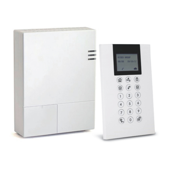
- Page 1 WiComm Pro Model: RW332M Quick Installation Guide Visit our website: www.riscogroup.com...
-
Page 2: Table Of Contents
Contents INTRODUCTION ....................4 INSTALLING THE SYSTEM .................. 4 2.1 Mounting Main unit considerations ..............4 2.2 To Install the Main Panel ................... 4 WIRELESS DEVICE ALLOCATION ................ 8 3.1 Allocating the Keypad and Selecting a Language ..........8 3.2 Wireless Device Allocation Options ..............9 Quick Device Allocation at the Main Panel .............. - Page 3 TECHNICAL SPECIFICATION ................26 Compliance Statement ....................27 STANDARD LIMITED PRODUCT WARRANTY .............28 08/2018 Page 3 5IN2484 B...
-
Page 4: Introduction
1. Introduction This quick installation guide describes the main steps for installing the main panel and programming the WiComm Pro using the Wireless Panda (2-Way LCD + Proximity) keypad. The WiComm Pro utilizes Cloud-based Smartphone and Web user apps and with advanced wireless security and safety features. - Page 5 Front access cover LED indicators Locking-screws (2) 2. Using the mounting bracket as a template, first mark and then drill all five holes on the wall (four mounting holes and one back tamper hole), then install the anchors.
- Page 6 Grooves for placing tabs from front cover (2) Back tamper screw location Wiring channel for network cable (shown with cable routed via hook) Opening for AC power cable (cable is installed onto the back of the panel only after the mounting bracket is secured to the wall) IP Module GSM Module...
- Page 7 5. Insert the SIM card into its holder, as required 6. Screw the antenna onto its connector on the GSM module 7. Install the GSM module in its cavity, with its connector fitting securely onto its respective socket. NOTE: Do not power-up the main panel yet. 8.
-
Page 8: Wireless Device Allocation
3. Wireless Device Allocation 3.1 Allocating the Keypad and Selecting a Language Newly installed systems require that the 2-way wireless LCD keypad be the first device to be allocated (enrolled) to the system, from which a default language is then defined. ... -
Page 9: Wireless Device Allocation Options
3.2 Wireless Device Allocation Options All wireless devices (detectors and accessories) must also be allocated (“enrolled”) to the system. This can be performed at: Main panel: Perform Quick Allocation of all devices by sending an RF signal transmission from each device to the main panel (see procedure below). -
Page 10: Wireless Device Rf Transmissions
Wireless Device RF Transmissions Wireless Device Transmission procedure 2-Way LCD Keypad Press simultaneously for at least 2 seconds 2-Way Panda Keypad Press simultaneously for at least 2 seconds. 2-Way Slim Keypad Press simultaneously for at least 2 seconds. PIR Detectors: ... -
Page 11: Programming The System
4.1 Programming with LCD/Panda Keypad This section describes system programming from the 2-way wireless LCD keypad. You can also program the WiComm Pro system via the Configuration Software (refer to the CS documentation and the Full Installation Manual). The following buttons are commonly used for programming (the buttons shown are for the 2-Way Wireless Panda LCD &... -
Page 12: Measuring And Defining The Noise Level Threshold
4.4 Measuring and Defining the Noise Level Threshold From the keypad you can measure (“calibrate”) the background noise that the main panel detects, and also define (“view/edit”) the acceptable threshold value, according to customer requirements. Background noise (RF interference) is typically generated by other non-system devices operating in close proximity to the system, and a large amount of background noise may interfere with the system, causing “jamming.”... -
Page 13: Performing A Communication Test
2. Enter the noise level threshold value you want between 00 –99, then press NOTE: Keep in mind the lower the number you set, the more “sensitive” the system will be (generating jamming events more frequently), and the higher the number you set, the “more tolerant”... -
Page 14: Programming & Testing Zones (Detectors)
4.7 Programming & Testing Zones (Detectors) The parameters available per zone (detector) may vary, according to the zone type. Refer to the instructions packaged with each detector. To program detector/zone parameters: 1. From the Installer menu select: 1)Programming > 2)Radio Device > 2)Modification >... -
Page 15: Programming And Testing Keyfobs
4.8 Programming and Testing Keyfobs Each keyfob can be set up to perform different system operations and control different utility outputs. Up to eight keyfobs can be enrolled in the system. The programming options under the parameters menu vary according to the type of the remote control (1-way or 2-way). -
Page 16: Programming Keypads
5) Panic Enable: Use to toggle between Y/N to define whether or not sending a panic alarm from the remote control is permitted (disabled by default). 6), 7), 8): Installer-assigned buttons 1 through 3 (for respective utility outputs). 4. Press to go back to the Keyfobs menu, and then select 2) Control. -
Page 17: Programming And Testing Sirens
4) Function key: Define the operation of the keys as either Panic Alarm, or Disabled. 8) Supervision: Use to toggle between Y/N. 3. Press to go back up to the Keypads menu, then select 2)Control and scroll to: RF Wakeup: Use to toggle between Y/N to define whether the keypad LCD will light up automatically during the Entry Delay time. -
Page 18: Connecting With Gsm/Gprs
4.12 Defining Monitoring Station Communication Reporting to monitoring station can be directly from the panel to the monitoring station receiver or routed through the RISCO cloud. For direct communication from the panel to the monitoring station you can define up to 3 monitoring station... - Page 19 To define monitoring station communication: 1. Use to go back up to 1)System > 2)Controls > 3)Communication > MSEnable > use to toggle between Y / N (select Y to enable) > 2. Use to go back up to 1)Programming > 4)Communication > 2)MS > scroll to select and define the options for the selected monitoring station (1—3).
-
Page 20: Defining Follow-Me Destinations
The WiComm Pro can notify end users of various system events. Reporting can be done directly from the WiComm Pro to the end user by SMS (up to 16). Reporting can also be by Email or Push Notification from the main unit or using the RISCO Cloud. -
Page 21: Setting System Parameters
NOTE: The actual destinations (telephone numbers, email addresses) are defined outside of the installer Programming menu, or can be done by the Grand Master from the User menus. NOTE: Additional Follow-Me e-mail destinations can be assigned in the RISCO Cloud. 4.14 Setting System Parameters System- parameters define how the system works and are located under the System menu. -
Page 22: Connecting To The Cloud
4.16 Connecting to the Cloud The system can be configured to be constantly connected to the RISCO Cloud - an application server that handles all communication between the system, service providers and Smartphone/Web users. The RISCO Cloud enables remote monitoring and control of the system, sending event notifications, and viewing real-time video clips via VUPoint IP cameras –... -
Page 23: Wireless Pir Camera Setup
4.17 Wireless PIR Camera Setup PIR-based camera detectors perform detection with advanced still image capabilities. Up to eight PIR cameras can be used in the WiComm Pro system. For the physical installation of PIR cameras, refer to the product instructions. -
Page 24: Testing The System
5. Testing the System Before leaving the site, it is important to fully test the system. [For allocated devices]: From the Installer menu, at 2)Testing you can perform the Communication test and battery test. [For the Main Panel]: From the Installer menu, at 2)Testing > 1)Main Panel you can perform the tests for noise level, siren, speaker, battery, as well as confirm the main panel software version and serial number. -
Page 25: Assisting The Customer
Instruct the user on how to define user codes and Follow-Me destinations. For RISCO Cloud connected communication, instruct users with Smartphones to download the iRISCO App from the Apple App store or Android Play Store, and ensure that the connection between the app and the system is established. - Page 26 7. Technical Specification Configuration Communication modes (modules) GPRS/GSM (2G), GSM (3G), IP, Wireless zones Wireless frequencies 868 MHz, 433 MHz Camera frequency 869.525 MHz, 916 MHz, 430 MHz 32 (includes 1 installer, 1 sub-installer, and 1 Grand System users (user codes) Master code) Follow-Me destinations ...
- Page 27 Average: 9µA Current consumption Peak:150 mA Compliance Statement Hereby, RISCO Group declares that the WiComm Pro series of central units and accessories are designed to comply with: • EN50131-1 • EN50131-3 Grade 2, Environmental Class II • EN50131-6 Type A •...
- Page 28 Risco, for a period of (i) 24 months from the date of connection to the Risco Cloud (for cloud connected products) or (ii) 24 months from production (for other products which are non-cloud connected), as the case may be (each, the “Product Warranty...
- Page 29 Consequently Risco shall have no liability for any personal injury, property damage or loss based on a claim that the product fails to give warning.
- Page 30 Directive 2014/53/EU. For the CE Declaration of Conformity please refer to our website: www.riscogroup.com Contacting RISCO Group RISCO Group is committed to customer service and product support. You can contact us through our website www.riscogroup.com or via the following: Australia...
- Page 31 This RISCO product was purchased at: 08/2018 Page 31 5IN2484 B...
- Page 32 No part of this document may be reproduced in any form without prior written permission from the publisher. © RISCO Group 08/2020. All rights reserved 5IN2484 B 08/2018 Page 32 5IN2484 B...
Need help?
Do you have a question about the WiComm Pro and is the answer not in the manual?
Questions and answers