Table of Contents
Advertisement
Quick Links
Advertisement
Chapters
Table of Contents

Related Manuals for Nokia ONT


Summary of Contents for Nokia ONT
- Page 1 Nokia ONT G-2426G-B Product Guide 3FE-49441-ABAA-TCZZA Issue 1 June 2021...
- Page 2 This document is intended for use by Nokia’s customers (“You”/”Your”) in connection with a product purchased or licensed from any company within Nokia Group of Companies. Use this document as agreed. You agree to notify Nokia of any errors you may find in this document;...
-
Page 3: Table Of Contents
Nokia ONT Contents About this document............................15 What’s new..............................21 Overview ............................21 What’s new in BBD Release 21.02 ....................21 ETSI ONT safety guidelines ........................23 Safety instructions ..........................23 Safety standards compliance ......................25 Electrical safety guidelines ........................26 ESD safety guidelines ........................26 Laser safety guidelines ........................27 Environmental requirements ......................30... - Page 4 General .............................69 Prerequisites .............................69 Recommended tools .........................69 Safety information ..........................70 Procedure............................71 Wall mount an G-2426G-B indoor ONT ....................73 Connect a UPS to a G-2426G-B ONT ....................78 Replace a G-2426G-B indoor ONT ......................87 Overview ............................87 Purpose .............................87 General .............................87 Prerequisites .............................87 Recommended tools .........................87...
- Page 5 Contents Nokia ONT 8.13 Viewing optics module status ......................111 8.14 Viewing statistics ..........................112 8.15 Viewing voice information........................115 Network configuration ..........................118 8.16 Overview ............................118 8.17 Configuring LAN ..........................118 8.18 Configuring LAN IPv6........................121 8.19 Configuring WAN..........................122 8.20 Configuring WAN DHCP .........................125 8.21 Configuring Wireless 2.4GHz ......................127...
- Page 6 RG Troubleshooting Counters ........................193 8.59 Overview ............................193 8.60 Viewing Residential Gateway (RG) troubleshooting counters............193 ON T configuration file over OMCI ......................197 Overview ............................197 Purpose ............................197 Supported configuration file types ....................197 ONT configuration file over OMCI ....................199 3FE-49441-ABAA-TCZZA June 2021 Issue 1...
- Page 7 G-2426G-B indoor ONT environmental specifications ..............61 Table 5-11 G-2426G-B, dimension data specifications..................61 Table 5-12 G-2426G-B indoor ONT capacity for GEM ports and T-CONTs .............62 Table 5-13 Package S ONTs ONTENET performance monitoring statistics ............63 Table 5-14 Package S ONTs ONTL2UNI performance monitoring statistics ...........63...
- Page 8 List of tables Nokia ONT Table 8-13 WAN parameters - Route mode ....................123 Table 8-14 WAN network parameters—Bridge Mode ..................125 Table 8-15 WAN DHCP parameters.......................126 Table 8-16 Wireless (2.4GHz) parameters.....................129 Table 8-17 Wireless (5GHz) parameters......................133 Table 8-18 IP Routing parameters .........................137 Table 8-19 DNS parameters ..........................138...
- Page 9 List of tables Nokia ONT Table 8-46 RG Troubleshooting Counters parameters ..................194 Table 9-1 Supported configuration files......................198 Table 9-2 Download configuration files ......................199 3FE-49441-ABAA-TCZZA June 2021 Issue 1...
- Page 10 List of tables Nokia ONT 3FE-49441-ABAA-TCZZA June 2021 Issue 1...
- Page 11 Figure 6-5 Wall mount bracket power cord placement..................76 Figure 6-6 ONT in wall mount bracket—facing the room ...................77 Figure 6-7 ONT in wall mount bracket—facing the room / facing the wall ............78 Figure 6-8 G-2426G-B ONT and UPS .......................79 Figure 6-9 Molex 7-pin DC cable ........................80 Figure 6-10 Installation of 3EM24378AB cable (7-pin) in Phoenix connector—3MV00807AA UPS 36W ..80...
- Page 12 Nokia ONT Figure 6-11 Connecting the AC cord to the wall outlet ..................81 Figure 6-12 Attaching the cable retainer ......................82 Figure 6-13 G-2426G-B ONT and PSI UPS.......................83 Figure 6-14 Battery pack onto Power Supply/Charger ..................84 Figure 7-1 G-2426G-B indoor ONT connections....................89 Figure 8-1 Web login page..........................97...
- Page 13 List of figures Nokia ONT Figure 8-29 QoS Config page (L2 packet sizes) ....................146 Figure 8-30 QoS Config page (L3 packet sizes) ....................147 Figure 8-31 Mesh page ............................149 Figure 8-32 Firewall page ..........................151 Figure 8-33 MAC Filter page..........................153 Figure 8-34 IP Filter page ..........................154 Figure 8-35 URL Filter page..........................156...
- Page 14 List of figures Nokia ONT Figure 8-62 Log page............................191 Figure 8-63 RG Troubleshooting Counters page .....................194 3FE-49441-ABAA-TCZZA June 2021 Issue 1...
-
Page 15: About This Document
About this document Purpose This documentation set provides information about safety, features and functionality, ordering, hardware installation and maintenance, and software installation procedures of this ONT for the current release. Intended audience This documentation set is intended for planners, administrators, operators, and maintenance personnel involved in installing, upgrading, or maintaining the ONTs. - Page 16 About this document Nokia ONT Nokia quality processes Nokia’s ONT manufacturing, testing, and inspecting practices are in compliance with TL 9000 requirements. These requirements are documented in the Fixed Networks Quality Manual 3FQ- 30146-6000-QRZZA. The quality practices adequately ensure that technical requirements and customer end-point requirements are met.
- Page 17 If you are a new user and require access to this service, please contact your Nokia sales representative. Select Products. Type your product name in the Find and select a product field and click the search icon.
- Page 18 About this document Nokia ONT This step has a series of substeps that you must perform to complete the step. You must perform the following substeps: a. This is the first substep. b. This is the second substep. c. This is the third substep.
- Page 19 Nokia ONT Technical support For details, refer to the Nokia Support portal (https://customer.nokia.com/support/s/). For ordering information, contact your Nokia sales representative. How to comment To comment on this document, go to the Online Comment Form (https://documentation.nokia.com/ comments/) or e-mail your comments to the Comments Hotline (mailto:comments@nokia.com).
- Page 20 About this document Nokia ONT 3FE-49441-ABAA-TCZZA June 2021 Issue 1...
-
Page 21: What's New
What’s new Nokia ONT Overview 1 What’s new 1.1 Overview 1.1.1 Purpose 1.1.2 Contents 1.1 Overview 1.2 What’s new in BBD Release 21.02 1.2 What’s new in BBD Release 21.02 The product guide is a new guide in BBD Release 21.02, issue 1. In future releases, this chapter will provide tables of the feature and document changes applicable to this guide. - Page 22 What’s new Nokia ONT What’s new in BBD Release 21.02 3FE-49441-ABAA-TCZZA June 2021 Issue 1...
-
Page 23: Etsi Ont Safety Guidelines
This chapter provides information about the mandatory regulations that govern the installation and operation of the optical network terminals (ONTs). 2.1 Safety instructions This section describes the safety instructions that are provided in the ONT customer documentation and on the equipment. 2.1.1 Safety instruction boxes The safety instruction boxes are provided in the ONT customer documentation. -
Page 24: Table 2-1 Safety Labels
Safety-related labels The ONT equipment is labeled with the specific safety instructions and compliance information that is related to a variant of the ONT. Observe the instructions on the safety labels. Table 2-1, “Safety labels” (p. 23) provides sample safety labels on the ONT equipment. -
Page 25: Safety Standards Compliance
2.2.4 Laser product standard compliance For most ONTs, the ONT equipment complies with EN 60825-1 and IEC 60825-2 for laser products. If there is an exception to this compliance regulation, you can find this information in the standards compliance section of the unit data sheet in this Product Guide. -
Page 26: Electrical Safety Guidelines
The use of any non-Nokia approved power supplies or power adapters is not supported or endorsed by Nokia. Such use will void any warranty or support contract with Nokia. Such use greatly increases the danger of damage to equipment or property. -
Page 27: Laser Safety Guidelines
Possibility of equipment damage. Risk of eye damage by laser radiation. 2.5.1 Laser classification The ONT is classified as a Class 1 laser product based on its transmit optical output. Laser warning labels The following figures show the labels related to laser product, classification and warning. -
Page 28: Figure 2-2 Laser Product Label
ETSI ONT safety guidelines Nokia ONT Laser safety guidelines Figure 2-2 Laser product label 18455 Figure 2-3, “Laser classification label” (p. 28) shows a laser classification label. Laser classification labels may be provided in other languages. Figure 2-3 Laser classification label... -
Page 29: Figure 2-4 Laser Warning Labels
Laser Warning Label 18993 2.5.2 Transmit optical output The maximum transmit optical output of an ONT is +5 dBm. 2.5.3 Normal laser operation In normal operation, fiber cable laser radiation is always off until it receives signal from the line terminal card. -
Page 30: Environmental Requirements
• The door of the ONT not be opened until temperature inside and outside the enclosure has stabilized. • If the door of the ONT must be opened after a rapid change in temperature or humidity, use a dry cloth to wipe down the metal interior to prevent the risk of condensation. -
Page 31: Etsi Environmental And Crohs Guidelines
This chapter provides information about the ETSI environmental China Restriction of Hazardous Substances (CRoHS) regulations that govern the installation and operation of the optical line termination (OLT) and optical network termination (ONT) systems. This chapter also includes environmental operation parameters of general interest. -
Page 32: Figure 3-2 Products Above Mcv Value Label
The label may be found in this documentation or on the product. Figure 3-2 Products above MCV value label Together with major international telecommunications equipment companies, Nokia has determined it is appropriate to use an EFUP of 50 years for network infrastructure equipment and an EFUP of 20 years for handsets and accessories. -
Page 33: Hazardous Substances Table (Hst)
ONT environmental requirements See the ONT technical specification documentation for more information about temperature ranges. 3.3.2 Storage According to ETS 300-019-1-1 - Class 1.1, storage of ONT equipment must be in Class 1.1, weather-protected, temperature-controlled locations. 3.3.3 Transportation According to EN 300-019-1-2 - Class 2.3, transportation of the ONT equipment must be in packed, public transportation with no rain on packing allowed. -
Page 34: Figure 3-3 Recycling/Take Back/Disposal Of Product Symbol
13 August 2005. Figure 3-3 Recycling/take back/disposal of product symbol At the end of their life, the OLT and ONT products are subject to the applicable local legislations that implement the European Directive 2012/19EU on waste electrical and electronic equipment (WEEE). -
Page 35: Ansi Ont Safety Guidelines
(ONTs or ONUs) in the North American or ANSI market. 4.1 Safety instructions This section describes the safety instructions that are provided in the ONT customer documentation and on the equipment. 4.1.1 Safety instruction boxes in customer documentation The safety instruction boxes are provided in the ONT customer documentation. -
Page 36: Table 4-1 Safety Labels
4.1.2 Safety-related labels The ONT equipment is labeled with specific safety compliance information and instructions that are related to a variant of the ONT. Observe the instructions on the safety labels. Table 4-1, “Safety labels” (p. 35) provides examples of the text in the various ONT safety labels. -
Page 37: Safety Standards Compliance
ANSI ONT safety guidelines Nokia ONT Safety standards compliance Figure 4-1, “Sample safety label on the ONT equipment” (p. 36) shows a sample safety label on the ONT equipment. Figure 4-1 Sample safety label on the ONT equipment Tested to Comply... -
Page 38: Figure 4-2 Sample Laser Product Label Showing Cdrh 21 Cfr Compliance
42 for ONTs containing Class 1 Laser modules certified by original manufactures. Per CDRH 21 CFR 10.40.10 (h) (1) (iv) distributors of Class 1 laser products, such as Nokia ONTs shall leave the following Laser Safety cautions with the end user. -
Page 39: Laser Safety Guidelines
Possibility of equipment damage. Risk of eye damage by laser radiation. Per CDRH 21 CFR 10.40.10 (h) (1) (iv) distributors of Class 1 laser products, such as Nokia ONTs shall leave the following Laser Safety cautions with the end user. -
Page 40: Figure 4-3 Laser Product Label
ANSI ONT safety guidelines Nokia ONT Laser safety guidelines 4.3.1 Laser warning labels The following figures show sample labels related to laser product, classification and warning. Figure 4-3, “Laser product label” (p. 39) shows a laser product label. Figure 4-3 Laser product label 18455 Figure 4-4, “Laser classification label”... -
Page 41: Figure 4-5 Laser Warning Labels
4.3.2 Laser classification The ONT is classified as a Class 1 laser product based on its transmit optical output. For Class 1 laser products, lasers are safe under reasonably foreseeable conditions of operation, including the use of optical instruments for intrabeam viewing. -
Page 42: Electrical Safety Guidelines
Figure 4-6 CDRH & CFR label 4.3.3 Transmit optical output The maximum transmit optical output of an ONT is +5 dBm. 4.3.4 Normal laser operation In normal operation, fiber cable laser radiation is always off until it receives signal from the line terminal card. -
Page 43: Esd Safety Guidelines
• The door of the ONT not be opened until temperature inside and outside the enclosure has stabilized. • If the door of the ONT must be opened after a rapid change in temperature or humidity, use a dry cloth to wipe down the metal interior to prevent the risk of condensation. - Page 44 ANSI ONT safety guidelines Nokia ONT Environmental requirements • When high humidity is present, installation of a cover or tent over the ONT helps prevent condensation when the door is opened. 3FE-49441-ABAA-TCZZA June 2021 Issue 1...
-
Page 45: 2426G-B Unit Data Sheet
5.12 G-2426G-B special considerations 5.2 G-2426G-B part numbers and identification Table 5-1, “Identification of G-2426G-B indoor ONTs” (p. 45) provides part numbers and identification information for the G-2426G-B indoor ONT. Table 5-1 Identification of G-2426G-B indoor ONTs Ordering kit Provisioning... -
Page 46: Table 5-2 G-2426G-B Power Supply Ordering Information
Table 5-2, “G-2426G-B power supply ordering information” (p. 46) provides the power supply information for the G-2426G-B ONT. For more information on power supplies, see the Nokia ONT Power Supply and UPS Guide. Table 5-2 G-2426G-B power supply ordering information... -
Page 47: G-2426G-B General Description
ONT unit The G-2426G-B ONT Wall mount bracket The wall mount bracket is fastened to a wall. The G-2426G-B ONT is seated in the wall mount bracket. With white color, 1 pc per box (3FE 49761 AA) Wall mount bracket The wall mount bracket is fastened to a wall. -
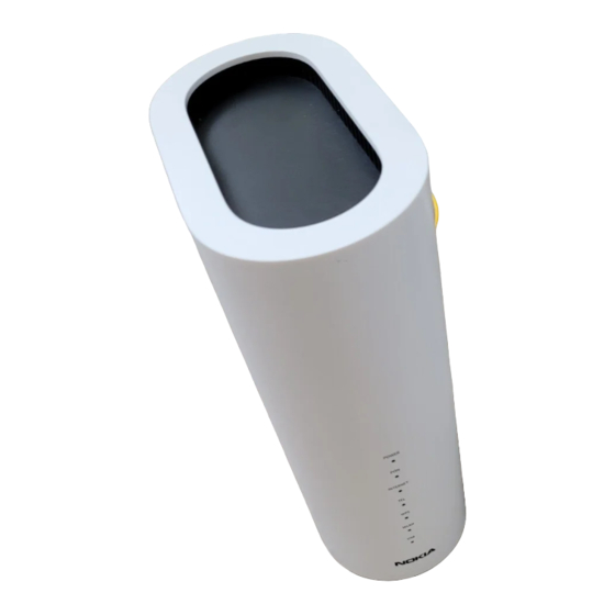
Page 48: Figure 5-1 G-2426G-B Ont
ID boxes (Type I, Type II, and Type III). The ONT can be placed on a flat surface, such as a desk or shelf. Figure 5-1 G-2426G-B ONT... -
Page 49: Figure 5-2 G-2426G-B Ont For Nar Variant
G-2426G-B unit data sheet Nokia ONT G-2426G-B general description Figure 5-2 G-2426G-B ONT for NAR variant 36371 G-2426G-B indoor ONTs provide the following functions: • Dual-band concurrent 4x4 IEEE 802.11b/g/n/ax 2.4 GHz and 802.11ac MU-MIMO 5 GHz • Supports 802.11 b/g/n/ax 4x4 Wireless 2.4 GHz MIMO; Channel bandwidth 20, 40 MHz, auto •... - Page 50 • Caller ID, call waiting, call hold, 3-way calling, call transfer, message waiting • Forward Error Correction (FEC) • support for multiple SSIDs (private and public instances); contact your Nokia representative for further details. • Conductive power: 500mW/27 dBm (2.4 GHz); 1000mW/30 dBm (5GHz) •...
- Page 51 • TR181 supported for selected customers with dedicated Pre-Config The following features are not supported on a mesh extending beacon and only supported in the mesh root device or when the ONT works as a standalone device: • Domain group/isolation •...
- Page 52 “Optics Module Status parameters” (p. 112) Chapter 8, “Configure a G-2426G-B indoor ONT”. Object support for Wi-Fi parameters The ONT supports the status retrieval and configuration of the following Wi-Fi parameters via TR- 069: • channel • SSID • password for WPA and WEP •...
- Page 53 The vendor specific attribute is: X_ALU-COM_XML_File_Name_Path. 5.3.4 TR-104 voice-related alarms The G-2426G-B ONT supports the following four TR-104 voice-related alarms on a per FXS port basis. These alarms all represent SIP registration failures with an alarm level of MAJOR. • SIPREGDNS: domain name could not be resolved •...
-
Page 54: G-2426G-B Software And Installation Feature Support
NAT gateway. 5.3.7 TR-157 support This ONT can support LXC container for third party software components on ONTs with minimal 512M memory. These software components are managed by ACS with the parameters defined in TR-157. -
Page 55: Figure 5-3 G-2426G-B Indoor Ont Physical Connections (Back) Nar
G-2426G-B connections and components Figure 5-3, “G-2426G-B indoor ONT physical connections (back) NAR” (p. 55) shows the physical connections for G-2426G-B indoor ONTs. Two USB port is on the side of the ONT. Figure 5-3 G-2426G-B indoor ONT physical connections (back) NAR 36372... -
Page 56: Figure 5-4 G-2426G-B Indoor Ont Physical Connections (Back)
Nokia ONT G-2426G-B interfaces and interface capacity Figure 5-4 G-2426G-B indoor ONT physical connections (back) 36373 Figure 5-5, “G-2426G-B indoor ONT with fiber optic connector” (p. 57) shows the G-2426G-B indoor ONT with a fiber optic connector. 3FE-49441-ABAA-TCZZA June 2021... -
Page 57: Table 5-6 G-2426G-B Indoor Ont Physical Connections
Reset button RESET Pressing the Reset button for less than 10 seconds reboots the ONT; pressing the Reset button for 10 seconds resets the ONT to the factory defaults, except for the LOID and SLID. WLAN button WLAN Wi-Fi service is compliant with IEEE 802.11 standards and is enabled and disabled using the WLAN button. -
Page 58: G-2426G-B Leds
Print Letters Description USB port This connection is provided through 1 USB 3.0 port on the side of the ONT. The ONT supports external USB hard drives that can be made accessible to all LAN devices. Fiber optic port The SC/APC fiber optic port is located at the back of the ONT and provides the connection for the fiber optic cable. -
Page 59: Table 5-7 G-2426G-B Indoor Ont Led Descriptions
G-2426G-B unit data sheet Nokia ONT G-2426G-B LEDs Figure 5-7 G-2426G-B indoor ONT LEDs for NAR variant POWER INTERNET WLAN 36735 Table 5-7, “G-2426G-B indoor ONT LED descriptions” (p. 59) provides LED descriptions for G-2426G-B indoor ONTs. Table 5-7 G-2426G-B indoor ONT LED descriptions... - Page 60 LED color and behavior LED behavior description No fiber connected or no rx power Green solid ONT has been configured on the OLT and is in service (UP) Flashing Green ONT is attempting to range with OLT solid Red GPON is down or no link connected.
-
Page 61: G-2426G-B Detailed Specifications
Weight [within ± 0.5 lb (0.23 kg)] 1.81 lbs (825g) (net weight of ONT) Table 5-9, “G-2426G-B indoor ONT power consumption specifications” (p. 61) lists the power consumption specifications for G-2426G-B indoor ONT. Table 5-9 G-2426G-B indoor ONT power consumption specifications... -
Page 62: G-2426G-B Gem Ports And T-Conts
The following section identifies the supported performance monitoring statistics for G-2426G-B ONTs. A check mark indicates the statistic is supported on that ONT. An empty cell indicates the statistic is not supported. The following tables are categorized by supported alarm types: •... -
Page 63: Table 5-13 Package S Onts Ontenet Performance Monitoring Statistics
✓ — Notes: 1. A 5 second polling window limitation exists on the ONT, therefore the margin of error for each 15-min window is 5 seconds 2. Only packets larger than 9 kB will be counted. Table 5-14 Package S ONTs ONTL2UNI performance monitoring statistics... -
Page 64: G-2426G-B Functional Blocks
Nokia ONT G-2426G-B functional blocks Notes: 1. A 5 second polling window limitation exists on the ONT, therefore the margin of error for each 15-min window is 5 seconds Table 5-16 Package S ONTs PONONTTC aggregate performance monitoring statistics PONONTTC (aggregate) statistics G-2426G-B —... -
Page 65: G-2426G-B Standards Compliance
• G.984.3 support for FEC in both upstream and downstream directions • G.984.3 support for multicast using a single GEM Port-ID for all video traffic • G.984.4 and G.983.2 support for ONT management and provisioning • IEEE 802.1p for traffic prioritization •... - Page 66 5.11.1 Energy-related products standby and off modes compliance Hereby, Nokia declares that the G-2426G-B ONTs are in compliance with the essential requirements and other relevant provisions of Directive 2009/125/EC together with Commission Regulation (EC) No 1275/2008 and Commission Regulation (EC) No 801/2013.
-
Page 67: G-2426G-B Special Considerations
G-2426G-B indoor ONTs feature Wi-Fi service as well as voice and data services. Wi-Fi is a wireless networking technology that uses radio waves to provide wireless HSI and network connections. This ONT complies with the IEEE 802.11 standards, which the Wi-Fi Alliance defines as the basis for Wi-Fi technology. - Page 68 • Enable Caller ID and Enable Caller Name ID • Digitmap and the associated Interdigit and Critical timers and Enter key parameters • Warmline timer is enabled per subscriber, but the warmline timer value is configured per ONT and must have a lower value than the Permanent time •...
-
Page 69: Install A G-2426G-B Indoor Ont
6.2 Purpose This chapter provides the steps to install a G-2426G-B indoor ONT. 6.3 General The steps listed in this chapter describe mounting and cabling for a G-2426G-B indoor ONT. 6.4 Prerequisites You need the following items before beginning the installation: •... -
Page 70: Safety Information
Observe the following: • The indoor ONT should be installed in accordance with the applicable requirements of the NEC or CEC. Local authorities and practices take precedent when there is conflict between the local standard and the NEC or CEC. -
Page 71: Procedure
6.7 Procedure Use this procedure to install a G-2426G-B indoor ONT. Place the indoor ONT unit on a flat surface, such as a desk or shelf. Note: The G-2426G-B cannot be stacked with another ONT or with other equipment. The ONT mounting requirements are: •... -
Page 72: Figure 6-2 G-2426G-B Ont Connections For Nar Variant
Install a G-2426G-B indoor ONT Nokia ONT Procedure Figure 6-2 G-2426G-B ONT connections for NAR variant Wi-Fi security/ on/off buttons Ethernet ports (4) (RJ-45) POTS ports (2) (RJ-11) On/off button Power 36737 Connect the Ethernet cables to the RJ-45 ports. -
Page 73: Wall Mount An G-2426G-B Indoor Ont
6.8 Wall mount an G-2426G-B indoor ONT This chapter provides the steps to mount an G-2426G-B indoor ONT on a wall using a wall mount bracket (3FE 49761 AA). The G-2426G-B indoor ONT is shipped without the wall mount bracket. -
Page 74: Figure 6-3 G-2426G-B Ont In Wall Mounting Bracket
2. See Figure 6-6, “ONT in wall mount bracket—facing the room” (p. 77). Mount the ONT on a wall facing the room using the wall mount bracket (3FE 49761 AA), as shown in Figure 6-4, “G-2426G-B wall mount bracket” (p. 75). -
Page 75: Figure 6-4 G-2426G-B Wall Mount Bracket
It is recommended to use a level to ensure that the ONT unit is installed properly. b. Drill two holes 35 mm (1.37 in.) depth into the wall and with the centers spaced 157 mm (6.2 in.). -
Page 76: Figure 6-5 Wall Mount Bracket Power Cord Placement
Connect the cables. i. Hang the unit onto the wall. Figure 6-6, “ONT in wall mount bracket—facing the room” (p. 77) shows the cables routed through the wall mount bracket and the ONT facing the room. 3FE-49441-ABAA-TCZZA June 2021... -
Page 77: Figure 6-6 Ont In Wall Mount Bracket-Facing The Room
It is recommended to use a level to ensure that the ONT unit is installed properly. b. Drill two holes 35 mm (1.37 in.) depth into the wall and with the centers spaced 157 mm (6.2 in.). -
Page 78: Connect A Ups To A G-2426G-B Ont
Remove the wall mount bracket from the wall. f. On a flat surface such as a desk, install the ONT into the wall mount bracket by lifting the unit above the bracket and sliding it downward onto the bottom ledge of the bracket. -
Page 79: Figure 6-8 G-2426G-B Ont And Ups
UPS connector 36308 The following figure shows an example ONT and UPS. The position of the connections may differ for each ONT model The connector for the 6 foot 3EM24378AA cable matches the socket for the 36W UPS Cyberpower DTC36U12V3-G. -
Page 80: Figure 6-9 Molex 7-Pin Dc Cable
Install a G-2426G-B indoor ONT Nokia ONT Connect a UPS to a G-2426G-B ONT Figure 6-9 Molex 7-pin DC cable 2438.4 + _ 30 mm (8ft + _ 1 in.) Black Brown White Orange Blue Yellow 28489 The 25 foot 3EM24378AB cable has one open end and must be terminated by the Phoenix connector provided with the UPS. -
Page 81: Figure 6-11 Connecting The Ac Cord To The Wall Outlet
UPS connector 36306 The following figure shows an example ONT and UPS. The position of the connections may differ for each ONT model c. Attach a cable retainer to the UPS power AC cord and the power cable, as shown in Figure 6-12, “Attaching the cable retainer”... -
Page 82: Figure 6-12 Attaching The Cable Retainer
• UPS AC power cable Place the indoor ONT unit and the UPS on a flat surface, such as a desk. Plug the cable into the UPS connector on the G-2426G-B ONT and the output connector on the UPS, as shown in Figure 6-13, “G-2426G-B ONT and PSI UPS”... -
Page 83: Figure 6-13 G-2426G-B Ont And Psi Ups
AC power cable 36155 The following figure shows an example ONT and UPS. The position of the connections may differ for each ONT model Remove the back cover to expose the battery connectors. Slide Battery pack onto Power Supply/Charger unit until the Battery Pack becomes fully flushed with Power Supply/ Charger as shown in Figure 6-14, “Battery pack onto Power Supply/Charger”... - Page 84 Install a G-2426G-B indoor ONT Nokia ONT Connect a UPS to a G-2426G-B ONT Figure 6-14 Battery pack onto Power Supply/Charger Battery Pack Power supply/Charger Power supply/ Charger Battery Pack 36154 Plug the 3 prong AC power cord plug end into standard 3 prong AC receptacle rated for 3 prong AC plug on bottom of power supply/charger as shown in Figure 6-13, “G-2426G-B ONT and PSI...
- Page 85 Ensure that the “System Status” LED is only the one in green illumination. If any other LED is illuminated recheck the battery pack is seated and ensure that all wiring from UPS to G-2426G-B ONT is installed correctly as listed by ONT specific instructions. ND OF STEPS...
- Page 86 Install a G-2426G-B indoor ONT Nokia ONT Connect a UPS to a G-2426G-B ONT 3FE-49441-ABAA-TCZZA June 2021 Issue 1...
-
Page 87: Replace A G-2426G-B Indoor Ont
7.2 Purpose This chapter provides the steps to replace a G-2426G-B indoor ONT. 7.3 General The steps listed in this chapter describe mounting and cabling for a G-2426G-B indoor ONT. 7.4 Prerequisites You need the following items before beginning the installation: •... -
Page 88: Safety Information
Observe the following: • The indoor ONT should be installed in accordance with the applicable requirements of the NEC or CEC. Local authorities and practices take precedent when there is conflict between the local standard and the NEC or CEC. -
Page 89: Figure 7-1 G-2426G-B Indoor Ont Connections
Procedure Deactivate the ONT services at the P-OLT. If you are using the SLID feature, this step is not required. The ONT and the services can remain in service (IS). a. Use the RTRV-ONT command to verify the ONT status and th associated services. Record the serial number or the SLID of the ONT displayed in the command output. - Page 90 Attach a fiber dust cover to the end of the SC/APC connector. Replace the old ONT with a new ONT on a flat surface, such as a desk or shelf. Connect the Ethernet cables directly to the RJ-45 ports; see Figure 7-1, “G-2426G-B indoor...
- Page 91 If used, configure the SLID; see the Nokia ONT Configuration, Management, and Troubleshooting Guide for more information. Note: A new SLID or the old SLID may be used with the replacement ONT. If a new SLID is used, the new SLID must also be programmed at the P-OLT using TL1 or a network manager.
- Page 92 Replace a G-2426G-B indoor ONT Nokia ONT Procedure Activate and test the services; see the Nokia ONT Hardware and Cabling Installation Guide. If necessary, reset the ONT. a. Locate the Reset button on a G-2426G-B indoor ONT as shown in Figure 7-1, “G-2426G-B...
-
Page 93: Configure A G-2426G-B Indoor Ont
Configure a G-2426G-B indoor ONT Nokia ONT Overview 8 Configure a G-2426G-B indoor ONT 8.1 Overview 8.1.1 Purpose 8.1.2 Contents 8.1 Overview GUI configuration 8.2 General configuration 8.3 HGU mode GUI configuration 8.4 Log in to web-based GUI Viewing device information and connection status 8.5 Overview... - Page 94 Configure a G-2426G-B indoor ONT Nokia ONT Overview 8.22 Configuring Wireless 5GHz 8.23 Configuring wireless scheduling 8.24 Configuring IP routing 8.25 Configuring DNS 8.26 Configuring TR-069 8.27 Configuring GRE tunnel 8.28 Configuring Upstream (US) Classifier 8.29 Configuring QoS 8.30 Configuring Mesh Security configuration 8.31 Overview...
- Page 95 Configure a G-2426G-B indoor ONT Nokia ONT Overview 8.50 Configuring SLID 8.51 Managing the device 8.52 Backing up the configuration 8.53 Restoring the configuration 8.54 Upgrading firmware 8.55 Rebooting the device 8.56 Resetting to factory defaults 8.57 Diagnosing WAN connections 8.58 Viewing log files...
-
Page 96: Gui Configuration
The default gateway IP address must be same as the one printed on the device label. You can connect to this IP address using your web browser after connecting your PC to one of Ethernet ports of the ONT. The static IP address of your PC must be in the same default gateway subnet as the ONT. -
Page 97: Figure 8-1 Web Login Page
Click Login. The Device Information page displays. Note: To help protect the security of your Internet connection, it is recommended to modify both the Wi-Fi password and the ONT WEBGUI login password as soon as possible if you have read and edit permissions. -
Page 98: Viewing Device Information And Connection Status
Configure a G-2426G-B indoor ONT Nokia ONT Viewing device information and connection status Overview Viewing device information and connection status 8.5 Overview 8.5.1 Purpose This chapter describes procedures to view device information and connection status on the G-2426G-B. 8.5.2 Contents 8.5 Overview... -
Page 99: Table 8-1 Device Information Parameters
Configure a G-2426G-B indoor ONT Nokia ONT Viewing device information and connection status Viewing device information Figure 8-2 Device Information page Note: Upon login, the GPON Home Gateway page displays the WAN status block on the bottom left part of each page. This block shows the WAN connection ID, the WAN status, and any WAN errors. -
Page 100: Viewing Lan Status
Configure a G-2426G-B indoor ONT Nokia ONT Viewing device information and connection status Viewing LAN status Click Refresh to display up-to-date information. ND OF STEPS 8.7 Viewing LAN status Click Status→LAN Status from the left pane in the GPON Home Gateway page. The LAN Status page displays. -
Page 101: Table 8-2 Lan Status Parameters
Configure a G-2426G-B indoor ONT Nokia ONT Viewing device information and connection status Viewing LAN status Figure 8-3 LAN Status page Table 8-2 LAN Status parameters Field Description Wireless Information Wireless Status Indicates whether the wireless is on or off... -
Page 102: Viewing Wan Status
Configure a G-2426G-B indoor ONT Nokia ONT Viewing device information and connection status Viewing WAN status Table 8-2 LAN Status parameters (continued) Field Description SSID Name Name of each SSID Wireless Encryption Status Encryption type used on the wireless connection Wireless... -
Page 103: Table 8-3 Wan Status Parameters
Configure a G-2426G-B indoor ONT Nokia ONT Viewing device information and connection status Viewing WAN status Figure 8-4 WAN Status page Table 8-3 WAN Status parameters Field Description WAN Connection List Drop-down menu listing all WAN connections. The connection shown is the connection for which WAN status will be shown. -
Page 104: Viewing Wan Ipv6 Status
Configure a G-2426G-B indoor ONT Nokia ONT Viewing device information and connection status Viewing WAN IPv6 status Table 8-3 WAN Status parameters (continued) Field Description Tx Packets Number of packets transmitted on the WAN connection Rx Packets Number of packets received on the WAN connection... -
Page 105: Table 8-4 Wan Status Ipv6 Parameters
Configure a G-2426G-B indoor ONT Nokia ONT Viewing device information and connection status Viewing WAN IPv6 status Figure 8-5 WAN Status IPv6 page Table 8-4 WAN Status IPv6 parameters Field Description WAN Connection List Drop-down menu listing all WAN connections. The connection shown is the connection for which WAN status will be shown. -
Page 106: Viewing Sta Information
Configure a G-2426G-B indoor ONT Nokia ONT Viewing device information and connection status Viewing STA information Table 8-4 WAN Status IPv6 parameters (continued) Field Description Second DNS Secondary Domain Name Server PON Link Status Whether the PON link is up or down... -
Page 107: Table 8-5 Sta Information Parameters
Configure a G-2426G-B indoor ONT Nokia ONT Viewing device information and connection status Viewing STA information Figure 8-6 STA Information page Table 8-5 STA information parameters Field Description MAC Address MAC address of the Ethernet connection SSID Name Name of each SSID... -
Page 108: Viewing Neighboring Access Points
Configure a G-2426G-B indoor ONT Nokia ONT Viewing device information and connection status Viewing Neighboring Access Points 8.11 Viewing Neighboring Access Points Click Status→Neighboring AP from the left pane in the GPON Home Gateway page. The Neighboring Access Points page displays the following information. -
Page 109: Viewing Home Networking Information
Configure a G-2426G-B indoor ONT Nokia ONT Viewing device information and connection status Viewing home networking information Table 8-6 Neighboring AP parameters (continued) Field Description Wi-Fi Mode Indicates the Wi-Fi mode Network Type Indicates the network type Click Scan. ND OF STEPS 8.12 Viewing home networking information... -
Page 110: Table 8-7 Home Networking Parameters
Configure a G-2426G-B indoor ONT Nokia ONT Viewing device information and connection status Viewing home networking information Figure 8-8 Home Networking page Table 8-7 Home Networking parameters Field Description Local Interface Ethernet Table displays the number of Ethernet connections and their settings Wireless Table displays the number of wireless connections and their settings (2.4GHz and 5GHz) -
Page 111: Viewing Optics Module Status
Configure a G-2426G-B indoor ONT Nokia ONT Viewing device information and connection status Viewing optics module status Table 8-7 Home Networking parameters (continued) Field Description Table entry Each entry indicates the status (active or inactive), connection type, device name, IP address, hardware address, IP address allocation, lease remaining, and last active time of each connected local device. -
Page 112: Viewing Statistics
Optics module voltage, measured in V Optics Module Temperature (ONT ANI-ONT-Side Optical Measurements) Optics module temperature, measured in C Rx Optics Signal Level at 1490 nm (ONT ANI-ONT-Side Optical Received optics signal level at 1490 nm, measured in Measurements) Tx Optics Signal Level at 1310 nm (ONT ANI-ONT-Side Optical... -
Page 113: Figure 8-10 Lan Statistics Page
Configure a G-2426G-B indoor ONT Nokia ONT Viewing device information and connection status Viewing statistics Figure 8-10 LAN Statistics page GPON Home Gateway Logout Status>Statistics EA:J Status Overv1ew DeviCeInformation Refresh Status StalUS Status 1Pv6 LAN1 LAN2 LAN3 LAN4 COUNTERS lnformahon... -
Page 114: Figure 8-11 Wan Statistics Page
Configure a G-2426G-B indoor ONT Nokia ONT Viewing device information and connection status Viewing statistics Figure 8-11 WAN Statistics page GPON Home Gateway Logout Status>Statistics Status Device Information Status LAtl Refresh Status 1Pv6 Status Information COUfiTERS 1_VOIP_TR069_1t/TERHET_R_VID_381 2_1tiTERtiET_R_VID_1 081 3_0THER_R_VI0_981... -
Page 115: Viewing Voice Information
Configure a G-2426G-B indoor ONT Nokia ONT Viewing device information and connection status Viewing voice information Figure 8-12 WLAN Statistics page You can click Refresh to display up-to-date information. ND OF STEPS 8.15 Viewing voice information Click Status→Voice Information from the left pane in the GPON Home Gateway page. The... -
Page 116: Table 8-9 Voice Information Parameters
Configure a G-2426G-B indoor ONT Nokia ONT Viewing device information and connection status Viewing voice information Figure 8-13 Voice Information page Table 8-9 Voice Information parameters Field Description Line Select a line from the list. The default is Line 1. - Page 117 Configure a G-2426G-B indoor ONT Nokia ONT Viewing device information and connection status Viewing voice information Table 8-9 Voice Information parameters (continued) Field Description Register Error Reason SIP standard error reason for the register status This field is blank if the register is set to OK...
-
Page 118: Network Configuration
Configure a G-2426G-B indoor ONT Nokia ONT Network configuration Overview Network configuration 8.16 Overview 8.16.1 Purpose This chapter describes the network configuration tasks supported by G-2426G-B ONTs. 8.16.2 Contents 8.16 Overview 8.17 Configuring LAN 8.18 Configuring LAN IPv6 8.19 Configuring WAN 8.20 Configuring WAN DHCP... -
Page 119: Figure 8-14 Lan Page
Configure a G-2426G-B indoor ONT Nokia ONT Network configuration Configuring LAN Figure 8-14 LAN page Configure the following LAN parameters: 3FE-49441-ABAA-TCZZA June 2021 Issue 1... -
Page 120: Table 8-10 Lan Parameters
Select the port mode for each port and click Save: • Route Mode • Bridge Mode IPv4 Address Enter the IP address of the ONT. Subnet Mask Enter the subnet mask of the ONT. DHCP enable Select this checkbox to enable DHCP. -
Page 121: Configuring Lan Ipv6
Configure a G-2426G-B indoor ONT Nokia ONT Network configuration Configuring LAN IPv6 8.18 Configuring LAN IPv6 Click Network→LAN_IPv6 from the left pane in the GPON Home Gateway page. The LAN_ IPv6 page displays. Figure 8-15 LAN IPv6 page Configure the following parameters:... -
Page 122: Configuring Wan
Configure a G-2426G-B indoor ONT Nokia ONT Network configuration Configuring WAN Table 8-12 LAN IPv6 parameters (continued) Field Description DNS Server Select a DNS server from the list. Prefix Config Select a prefix config option from the list, either WANConnection (prefix will be obtained from the WAN) or Static (enables you to enter the prefix). -
Page 123: Table 8-13 Wan Parameters - Route Mode
Configure a G-2426G-B indoor ONT Nokia ONT Network configuration Configuring WAN Figure 8-16 WAN page - Route Mode Configure the following parameters for a specific WAN connection. Table 8-13, “WAN parameters - Route mode” (p. 123) describes the fields in the WAN network... -
Page 124: Table 8-14 Wan Network Parameters-Bridge Mode
Configure a G-2426G-B indoor ONT Nokia ONT Network configuration Configuring WAN Table 8-13 WAN parameters - Route mode (continued) Field Description Service Select the checkboxes to enable service types for this connection. Enable VLAN Select this checkbox to enable VLAN. -
Page 125: Configuring Wan Dhcp
Configure a G-2426G-B indoor ONT Nokia ONT Network configuration Configuring WAN DHCP Table 8-14 WAN network parameters—Bridge Mode Field Description WAN Connection List Choose a WAN connection from the drop-down menu to set the connection parameters Connection mode This option is only available for the operator ID MSNA, and for some operator-specific operator IDs. -
Page 126: Table 8-15 Wan Dhcp Parameters
Configure a G-2426G-B indoor ONT Nokia ONT Network configuration Configuring WAN DHCP Figure 8-18 WAN DHCP page Configure the following parameters: Table 8-15 WAN DHCP parameters Field Description WAN Connection List Select a WAN connection from the list. DHCP Option 50 Persistent Select this checkbox to enable DHCP Option 50 persistent. -
Page 127: Configuring Wireless 2.4Ghz
Configure a G-2426G-B indoor ONT Nokia ONT Network configuration Configuring Wireless 2.4GHz 8.21 Configuring Wireless 2.4GHz Click Network→Wireless (2.4GHz) from the left pane in the GPON Home Gateway page. The Wireless (2.4GHz) page displays. 3FE-49441-ABAA-TCZZA June 2021 Issue 1... -
Page 128: Figure 8-19 Wireless (2.4Ghz) Page
Configure G-2426G-B indoor ONT NokiaONT Network configuration Configuring Wireless 2.4GHz Figure 8-19 Wireless (2.4GHz) page GPON Home Gateway Logout Network>Wire less (2.4GHz) Status Enable Network aulo(blg/n/ax} Mode 20MHz Bandwidth lAN_ Auto Channel DHCP Transmitting Power 100% Wireless (2.4GHz) Enable Wire ess... -
Page 129: Table 8-16 Wireless (2.4Ghz) Parameters
Configure a G-2426G-B indoor ONT Nokia ONT Network configuration Configuring Wireless 2.4GHz Configure the following parameters: Table 8-16 Wireless (2.4GHz) parameters Field Description Enable Select this checkbox to enable Wi-Fi. Mode Select a Wi-Fi mode from the list: • auto (b/g/n/ax) •... - Page 130 Configure G-2426G-B indoor ONT NokiaONT Network configuration Configuring Wireless 2.4GHz Table 8-16 Wireless (2.4GHz) parameters (continued) Field Description Encryption Mode Select an encryption mode from the list: • OPEN • WEP • WPA/WPA2 Personal • WPA/WPA2 Enterprise • WPA2/WPA3 Personal •...
-
Page 131: Configuring Wireless 5Ghz
Configure a G-2426G-B indoor ONT Nokia ONT Network configuration Configuring Wireless 5GHz 5. Connect to this SSID all the necessary devices using the WPS button or entering the PIN in the devices. 6. When all desired devices have been connected, return to the WebGUI, select Disable in the Enable WPS field and click Save at the bottom of the menu. -
Page 132: Figure 8-20 Wireless (5Ghz) Page
Configure a G-2426G-B indoor ONT Nokia ONT Networl< configuration Configuring Wireless 5GHz Figure 8-20 Wireless (5GHz) page GPON Home Gateway Logout Network>Wire less (5GHz) Status Enab • Network 80MHz Bandwd Auto LAN_ IPv6 Channel WANDHCP 100% Transm tingPower Wire less (2.4GHz) -
Page 133: Table 8-17 Wireless (5Ghz) Parameters
Configure a G-2426G-B indoor ONT Nokia ONT Network configuration Configuring Wireless 5GHz Table 8-17 Wireless (5GHz) parameters Field Description Enable Select this checkbox to enable Wi-Fi. Bandwidth Select from: • 20 MHz • 40 MHz • 80 MHz Channel Select a channel from the list or select Auto to have the channel automatically assigned. -
Page 134: Configuring Wireless Scheduling
Configure a G-2426G-B indoor ONT Nokia ONT Network configuration Configuring wireless scheduling Table 8-17 Wireless (5GHz) parameters (continued) Field Description Create One New Domain Select this checkbox to create a new domain. WAN Interface Select a WAN interface from the list. -
Page 135: Figure 8-21 Wireless Schedule Page
Configure a G-2426G-B indoor ONT Nokia ONT Network configuration Configuring wireless scheduling Figure 8-21 Wireless Schedule page Select the Schedule Function checkbox to turn the wireless signal off for the configured period. Click the plus sign (+) to add a scheduling rule. -
Page 136: Configuring Ip Routing
Configure a G-2426G-B indoor ONT Nokia ONT Network configuration Configuring IP routing If desired, click the plus sign (+) to add more rules. Click Save Changes. ND OF STEPS 8.24 Configuring IP routing Click Network→IP Routing from the left pane in the GPON Home Gateway page. The IP Routing page displays. -
Page 137: Configuring Dns
Configure a G-2426G-B indoor ONT Nokia ONT Network configuration Configuring DNS Table 8-18 IP Routing parameters Field Description Enable Routing Select this checkbox to enable routing. Destination IP Address Enter the destination IP address. Destination Netmask Enter the destination network mask. -
Page 138: Table 8-19 Dns Parameters
Configure a G-2426G-B indoor ONT Nokia ONT Network configuration Configuring DNS Figure 8-23 DNS page Configure the following parameters: Table 8-19 DNS parameters Field Description DNS Proxy Select the Enabled checkbox to enable DNS proxy and click Save. Domain Name Enter the domain name. -
Page 139: Configuring Tr-069
Enter the username used to log in to the auto-configuration server. Password Enter the password used to log in to the auto-configuration server. Connect Request Username Enter the username used to log in to the ONT. 3FE-49441-ABAA-TCZZA June 2021 Issue 1... -
Page 140: Configuring Gre Tunnel
Configuring GRE tunnel Table 8-20 TR-069 parameters (continued) Field Description Connect Request Password Enter the password used to log in to the ONT. Click Save. Click Refresh to view the up-to-date information. ND OF STEPS 8.27 Configuring GRE tunnel Note: This feature is available to admin users (super users) only. -
Page 141: Configuring Upstream (Us) Classifier
Configure a G-2426G-B indoor ONT Nokia ONT Network configuration Configuring Upstream (US) Classifier Table 8-21 GRE Tunnel parameters Field Description Tunnel Name Select Create new GRE Tunnel or select an existing tunnel from the list. The tunnel name is automatically assigned by the system. -
Page 142: Table 8-22 Us Classifier Policy Parameters
Configure a G-2426G-B indoor ONT Nokia ONT Network configuration Configuring Upstream (US) Classifier Figure 8-26 US Classifier Policy page Select a tunnel interface. Table 8-22 US Classifier Policy parameters Field Description Tunnel Type The tunnel type is set to GRE and cannot be modified. -
Page 143: Table 8-23 Us Classifier Parameters
Configure a G-2426G-B indoor ONT Nokia ONT Network configuration Configuring Upstream (US) Classifier Click Delete for the applicable policy in the policy table, to delete a policy. Note: A policy can only be deleted if it is not associated with any classifier rules. - Page 144 Configure a G-2426G-B indoor ONT Nokia ONT Network configuration Configuring Upstream (US) Classifier Table 8-23 US Classifier parameters (continued) Field Description Source IP Click to enter a source IP address. Destination IP Click to enter a destination IP address. Source Port Click to enter a source port.
-
Page 145: Table 8-24 Us Classifier Rules Parameters
Configure a G-2426G-B indoor ONT Nokia ONT Network configuration Configuring Upstream (US) Classifier Figure 8-28 US Classifier Rules page Configure the classifier rule. Table 8-24 US Classifier Rules parameters Field Description Policy Select a policy from the list. Classifier Select a classifier from the list. -
Page 146: Configuring Qos
Configure a G-2426G-B indoor ONT Nokia ONT Network configuration Configuring QoS Click Save. Click Reset to reset the rules configured. Click Refresh to view the up-to-date information. Click Delete for the applicable classifier rules in the classifier rules table, to delete a classifier. -
Page 147: Figure 8-30 Qos Config Page (L3 Packet Sizes)
Configure a G-2426G-B indoor ONT Nokia ONT Network configuration Configuring QoS Figure 8-30 QoS Config page (L3 packet sizes) Configure the following parameters: 3FE-49441-ABAA-TCZZA June 2021 Issue 1... -
Page 148: Configuring Mesh
Configure a G-2426G-B indoor ONT Nokia ONT Network configuration Configuring Mesh Table 8-25 QoS Config parameters Field Description QoS Setting Type Select a QoS service layer type from the list L2 or L3. Classification Criteria Source MAC Enter the source MAC Select the Exclude checkbox to exclude the source MAC address. -
Page 149: Table 8-26 Mesh Parameters
Indicates the serial number of the extender Nokia Wi-Fi beacon device. Onboarding Status Indicates whether the extender Nokia Wi-Fi beacon associated with the serial number is configured to the mesh or not. If it is configured then the extender beacon MAC address is added to the Root. - Page 150 Field Description Friendly Name Indicates the friendly name that is defined while on-boarding the extender Nokia Wi-Fi beacon using the Nokia Wi-Fi Mobile Application. Note: The number of the entries in the mesh parameters table depends on number of extenders in the home network. If you have two extenders, then there will be two entries in the mesh parameters table.
-
Page 151: Security Configuration
Configure a G-2426G-B indoor ONT Nokia ONT Security configuration Overview Security configuration 8.31 Overview 8.31.1 Purpose This chapter describes the security configuration tasks supported by G-2426G-B ONTs 8.31.2 Contents 8.31 Overview 8.32 Configuring the firewall 8.33 Configuring the MAC filter 8.34 Configuring the IP filter... -
Page 152: Configuring The Mac Filter
Configure a G-2426G-B indoor ONT Nokia ONT Security configuration Configuring the MAC filter Configure the firewall. Table 8-27 Firewall parameters Field Description Security level Select the security level from the list: High: Traffic denied inbound and minimally permit common services outbound... -
Page 153: Table 8-28 Mac Filter Parameters
Configure a G-2426G-B indoor ONT Nokia ONT Security configuration Configuring the MAC filter Figure 8-33 MAC Filter page Configure the following parameters: Table 8-28 MAC Filter parameters Field Description Ethernet Interface MAC Filter Mode Select the MAC filter mode from the list: Blocked or Allowed. -
Page 154: Configuring The Ip Filter
Configure a G-2426G-B indoor ONT Nokia ONT Security configuration Configuring the IP filter Table 8-28 MAC Filter parameters (continued) Field Description SSID Select Select the SSID from the list. Enable Select this checkbox to enable the MAC filter. MAC Address Select a MAC address from the list or enter the address in the text field. -
Page 155: Configuring The Url Filter
• Accept for downstream Internal Client Select an internal client from the list: • Custom settings: uses the IP address input below • IP: uses the connecting devices' IP to the ONT Local IP Address Enter the local IP address. Source Subnet Mask Enter the source subnet mask. -
Page 156: Configuring Parental Control
Configure a G-2426G-B indoor ONT Nokia ONT Security configuration Configuring parental control Figure 8-35 URL Filter page Note: You cannot use URL filtering for HTTPS. The URL is encrypted when using HTTPS. Configure the following parameters: Table 8-30 URL Filter parameters... -
Page 157: Figure 8-36 Default Parental Control Page
Configure a G-2426G-B indoor ONT Nokia ONT Security configuration Configuring parental control Figure 8-36 Default Parental Control page Click Activate extended parental control to activate the extended version of parental control. Click OK in the pop-up window. The advanced parental control page displays. -
Page 158: Figure 8-37 Advanced Parental Control Page
Configure a G-2426G-B indoor ONT Nokia ONT Security configuration Configuring parental control Figure 8-37 Advanced Parental control page Click on the plus sign (+) to create a group. The create new group page displays 3FE-49441-ABAA-TCZZA June 2021 Issue 1... -
Page 159: Figure 8-38 Create New Group Page
Configure a G-2426G-B indoor ONT Nokia ONT Security configuration Configuring parental control Figure 8-38 Create new group page Click Add. You can click on each field such as Device, Access Internet, URL, Schedule, and Bed Time to configure the related parameters. -
Page 160: Figure 8-39 Parental Control Access Internet Page
Configure a G-2426G-B indoor ONT Nokia ONT Security configuration Configuring parental control Figure 8-39 Parental control access internet page The following page displays the parental control device information. 3FE-49441-ABAA-TCZZA June 2021 Issue 1... -
Page 161: Figure 8-40 Parental Control Device Page
Configure a G-2426G-B indoor ONT Nokia ONT Security configuration Configuring parental control Figure 8-40 Parental control device page The following page displays the parental control URL information. 3FE-49441-ABAA-TCZZA June 2021 Issue 1... -
Page 162: Figure 8-41 Parental Control Url Page
Configure a G-2426G-B indoor ONT Nokia ONT Security configuration Configuring parental control Figure 8-41 Parental control URL page The following page displays the parental control schedule information. 3FE-49441-ABAA-TCZZA June 2021 Issue 1... -
Page 163: Figure 8-42 Parental Control Schedule Page
Configure a G-2426G-B indoor ONT Nokia ONT Security configuration Configuring parental control Figure 8-42 Parental control schedule page The following page displays the parental control bed time information. 3FE-49441-ABAA-TCZZA June 2021 Issue 1... -
Page 164: Table 8-31 Parental Control Parameters
Configure a G-2426G-B indoor ONT Nokia ONT Security configuration Configuring parental control Figure 8-43 Parental control bed time page You can click Delete to delete the group. Configure the following parameters: Table 8-31 Parental control parameters Field Description Access Internet... -
Page 165: Configuring Dmz And Alg
Configure a G-2426G-B indoor ONT Nokia ONT Security configuration Configuring DMZ and ALG Table 8-31 Parental control parameters (continued) Field Description Device Device MAC Address Enter the MAC address and click Add Device. Enable URL Filter Select this checkbox to enable URL filter... -
Page 166: Table 8-32 Alg Parameters
Configure a G-2426G-B indoor ONT Nokia ONT Security configuration Configuring DMZ and ALG Figure 8-44 DMZ and ALG page Configure the following parameters: Table 8-32 ALG parameters Field Description ALG Config Select the checkboxes to enable the protocols to be supported by the ALG: FTP, TFTP, SIP, H323, RTSP, L2TP, IPSEC, PPTP. -
Page 167: Configuring Access Control
Configure a G-2426G-B indoor ONT Nokia ONT Security configuration Configuring access control Click Save DMZ. ND OF STEPS 8.38 Configuring access control This procedure describes how to configure the access control level (ACL). Note: ACL takes precedence over the firewall policy. -
Page 168: Table 8-34 Access Control Parameters
Configure a G-2426G-B indoor ONT Nokia ONT Security configuration Configuring access control Table 8-34 Access Control parameters Field Description Select a connection from the list. Trusted Network Enable Click to enable or disable trusted network. ICMP, Telnet, SSH, HTTP, TR-069, HTTPS,... -
Page 169: Configuring The Application
Configure a G-2426G-B indoor ONT Nokia ONT Configuring the Application Overview Configuring the Application 8.39 Overview 8.39.1 Purpose This chapter describes the application configuration tasks supported by the G-2426G-B ONTs. 8.39.2 Contents 8.39 Overview 8.40 Configuring port forwarding 8.41 Configuring port triggering 8.42 Configuring DDNS... -
Page 170: Table 8-36 Port Forwarding Parameters
Configure a G-2426G-B indoor ONT Nokia ONT Configuring the Application Configuring port forwarding Figure 8-46 Port Forwarding page Configure the following parameters: Table 8-36 Port Forwarding parameters Field Description Application Name Select an application name from the list. The default is Custom settings. -
Page 171: Configuring Port Triggering
Configure a G-2426G-B indoor ONT Nokia ONT Configuring the Application Configuring port triggering Table 8-36 Port Forwarding parameters (continued) Field Description Description Enter the description. Click Add. ND OF STEPS 8.41 Configuring port triggering Click Application→Port Triggering from the left pane in the GPON Home Gateway page. The Port Triggering page displays. -
Page 172: Configuring Ddns
Configure a G-2426G-B indoor ONT Nokia ONT Configuring the Application Configuring DDNS Table 8-37 Port Triggering parameters Field Description Application Name Select an application name from the list. The default is Custom settings. Open Port Enter the open port range. -
Page 173: Configuring Ntp
Configure a G-2426G-B indoor ONT Nokia ONT Configuring the Application Configuring NTP Figure 8-48 DDNS page Configure the following parameters: Table 8-38 DDNS parameters Field Description WAN Connection List Select a WAN connection from the list. Enable DDNS Select this checkbox to enable DDNS on the selected WAN connection. -
Page 174: Table 8-39 Ntp Parameters
Configure a G-2426G-B indoor ONT Nokia ONT Configuring the Application Configuring NTP Configure the following parameters: Table 8-39 NTP parameters Field Description Enable NTP Service Select this checkbox to enable the NTP service. Click Save. You can click Refresh to get the up-to-date information. -
Page 175: Configuring Usb
Configure a G-2426G-B indoor ONT Nokia ONT Configuring the Application Configuring USB 8.44 Configuring USB You can connect USB storage devices and USB printers to the USB ports of the device. The USB menu enables you to configure FTP and SFTP for your USB storage devices. -
Page 176: Configuring Upnp And Dlna
Re-enter the password for the SFTP server. Connected USB Devices Table For each printer that is connected to the ONT, the following fields are displayed: • Host Number for example: Printer1, Printer2 • Device Name: name or identification for the USB device •... -
Page 177: Configuring Voice
Configure a G-2426G-B indoor ONT Nokia ONT Configuring the Application Configuring voice Figure 8-50 UPnP and DLNA page Select the Enable UPnP/DLNA checkbox to enable UPnP/DLNA. Click Save/Apply. ND OF STEPS 8.46 Configuring voice Click Application→Voice Setting from the left pane in the GPON Home Gateway page. The Voice Setting page displays. -
Page 178: Table 8-41 Voice Setting Parameters
Configure a G-2426G-B indoor ONT Nokia ONT Configuring the Application Configuring voice Figure 8-51 Voice Setting page Configure the following parameters: Table 8-41 Voice Setting parameters Field Description Voice Setting Outbound Proxy Enter the SIP outbound proxy. Outbound Proxy Port Enter the outbound proxy port. - Page 179 Configure a G-2426G-B indoor ONT Nokia ONT Configuring the Application Configuring voice Table 8-41 Voice Setting parameters (continued) Field Description Registrar Server Port Enter the registrar server port. UserAgentDomain Enter the user agent domain. UserAgentPort Enter the user agent port.
-
Page 180: Maintenance
Configure a G-2426G-B indoor ONT Nokia ONT Maintenance Overview Maintenance 8.47 Overview 8.47.1 Purpose This chapter describes the maintenance tasks supported by G-2426G-B ONTs. 8.47.2 Contents 8.47 Overview 8.48 Configuring the password 8.49 Configuring LOID 8.50 Configuring SLID 8.51 Managing the device 8.52 Backing up the configuration... -
Page 181: Table 8-42 Password Parameters
Configure a G-2426G-B indoor ONT Nokia ONT Maintenance Configuring the password • the first character cannot be a special character • there are not enough character classes Click Maintenance→Password from the left pane in the GPON Home Gateway page. The Password page displays. -
Page 182: Configuring Loid
Configure a G-2426G-B indoor ONT Nokia ONT Maintenance Configuring LOID Click Refresh to view the up-to-date information. ND OF STEPS 8.49 Configuring LOID Click Maintenance →LOID Config from the left pane in the GPON Home Gateway page. The LOID Config page displays. -
Page 183: Configuring Slid
Configure a G-2426G-B indoor ONT Nokia ONT Maintenance Configuring SLID Click Save/Apply. ND OF STEPS 8.50 Configuring SLID Click Maintenance→SLID Configuration from the left pane in the GPON Home Gateway page. The SLID Configuration page displays. Figure 8-54 SLID Configuration page... -
Page 184: Managing The Device
Configure a G-2426G-B indoor ONT Nokia ONT Maintenance Managing the device Click Save. Click Refresh to view the up-to-date information. ND OF STEPS 8.51 Managing the device Click Maintenance→Device Management from the left pane in the GPON Home Gateway page. The Device Management page displays. -
Page 185: Backing Up The Configuration
Click Maintenance→Backup and Restore from the left pane in the GPON Home Gateway page. The Backup and Restore page displays. Figure 8-56 Backup and Restore page Click Export to export the current ONT configuration to a backup file. ND OF STEPS 8.53 Restoring the configuration Click Maintenance→Backup and Restore from the left pane in the GPON Home Gateway... -
Page 186: Upgrading Firmware
Upgrading firmware Figure 8-57 Backup and Restore page Click Choose file and select the backup file. Click Import to restore the ONT to the saved backup. ND OF STEPS 8.54 Upgrading firmware Click Maintenance→Firmware Upgrade from the left pane in the GPON Home Gateway page. -
Page 187: Rebooting The Device
Configure a G-2426G-B indoor ONT Nokia ONT Maintenance Rebooting the device Figure 8-58 Firmware Upgrade page Click Choose file and select the firmware file. Click Upgrade to upgrade the firmware. ND OF STEPS 8.55 Rebooting the device Click Maintenance→Reboot Device from the left pane in the GPON Home Gateway page. -
Page 188: Resetting To Factory Defaults
Nokia ONT Maintenance Resetting to factory defaults Figure 8-59 Reboot Device page Click Reboot to reboot the ONT. ND OF STEPS 8.56 Resetting to factory defaults Click Maintenance→Factory Default from the left pane in the GPON Home Gateway page. The Factory Default page displays. -
Page 189: Diagnosing Wan Connections
Maintenance Diagnosing WAN connections Figure 8-60 Factory Default page Click Factory Default to reset the ONT to its factory default settings. ND OF STEPS 8.57 Diagnosing WAN connections Click Maintenance→Diagnostics from the left pane in the GPON Home Gateway page. The Diagnostics page displays. -
Page 190: Figure 8-61 Diagnostics Page
Configure a G-2426G-B indoor ONT Nokia ONT Maintenance Diagnosing WAN connections Figure 8-61 Diagnostics page Choose IPv4 or IPv6 to select the protocol type from the drop-down menu. Select a WAN connection to diagnose from the list. Enter the IP address or domain name. -
Page 191: Viewing Log Files
Configure a G-2426G-B indoor ONT Nokia ONT Maintenance Viewing log files Enter the maximum number of trace hops (1-255); the default is 30. Click Start Test. The results will be displayed at the bottom of the page. Click Cancel to cancel the test. - Page 192 Configure a G-2426G-B indoor ONT Nokia ONT Maintenance Viewing log files Select a write level from the list to determine which types of events are recorded in the log file: • Emergency • Alert • Critical • Error • Warning •...
-
Page 193: Rg Troubleshooting Counters
Configure a G-2426G-B indoor ONT Nokia ONT RG Troubleshooting Counters Overview RG Troubleshooting Counters 8.59 Overview 8.59.1 Purpose This section describes the RG troubleshooting counters GUI procedures. 8.59.2 Contents 8.59 Overview 8.60 Viewing Residential Gateway (RG) troubleshooting counters 8.60 Viewing Residential Gateway (RG) troubleshooting counters The Troubleshooting Counters feature enables service providers and end users to monitor the performance of their broadband connection. - Page 194 Configure a G-2426G-B indoor ONT Nokia ONT RG Troubleshooting Counters Viewing Residential Gateway (RG) troubleshooting counters Figure 8-63 RG Troubleshooting Counters page Configure the following parameters: Table 8-46 RG Troubleshooting Counters parameters Field Description WAN Connection List Select a WAN connection from the list.
- Page 195 Configure a G-2426G-B indoor ONT Nokia ONT RG Troubleshooting Counters Viewing Residential Gateway (RG) troubleshooting counters Table 8-46 RG Troubleshooting Counters parameters (continued) Field Description Latency This test is used to determine the lowest round-trip time in milliseconds by pinging the target server multiple times.
- Page 196 Configure a G-2426G-B indoor ONT Nokia ONT RG Troubleshooting Counters Viewing Residential Gateway (RG) troubleshooting counters 3FE-49441-ABAA-TCZZA June 2021 Issue 1...
-
Page 197: Ont Configuration File Over Omci
This procedure describes how to use configuration files over OMCI to configure ONTs. Some advantages include: • flexibility to change the ONT default behavior by downloading configuration file • flexibility to update a deployed ONT by downloading updated parameters • ability to securely download any configuration file to an ONT •... - Page 198 This file enables operators to change the voice behavior by downloading the updated voice XML file. Nokia recommends using this procedure, rather than embedded voice XML files. The Nokia defined index for the Voice XML file is: "XML" 3FE-49441-ABAA-TCZZA June 2021 Issue 1...
-
Page 199: Ont Configuration File Over Omci
9.3.1 Filename conventions Nokia provides the raw configuration files, which must be saved by the operator in a TAR file to be uploaded. TAR file names must be unique. The filenames of the raw configuration files may not adhere to the naming conventions outlined below. - Page 200 The OLT will download the XML file from "sw-ctr-list" (configure equipment ont sw-ctrl) ND OF STEPS The ONT will distribute the configuration files to the different services based on the active indication from the OLT and on the Nokia defined index.
- Page 201 If pland-cfgfileX= Disabled and dnload-cfgfileX= Disabled , no file will be downloaded to the ONT. b. If pland-cfgfileX=FILENAME1 and dnload-cfgfileX= Disabled , FILENAME1 will be downloaded and FILENAME1 will be made active. An ONT reboot is required. c. If pland-cfgfileX=Disabled and dnload-cfgfileX= FILENAME2...
- Page 202 The OLT will download the XML file from "sw-ctr-list" (configure equipment ont sw-ctrl) ND OF STEPS The ONT will distribute the configuration files to the different services based on the active indication from the OLT and on the Nokia defined index.
Need help?
Do you have a question about the ONT and is the answer not in the manual?
Questions and answers