Table of Contents
Advertisement
Quick Links
Advertisement
Table of Contents

Related Manuals for ABB Welcome IP


Summary of Contents for ABB Welcome IP
- Page 1 System Manual │ 23.02.2021 ABB-Welcome IP Branding -- Release 2018-01-01...
-
Page 2: Table Of Contents
1.2.1 Basic principles ..........................7 1.2.2 Wiring of a ABB-Welcome IP system ..................11 1.2.3 Ports a services in a ABB-Welcome IP system ................13 Major projects ........................... 14 Overview of product range .......................... 15 Outdoor stations ..........................15 2.1.1 Devices ............................ - Page 3 Commissioning ............................62 Overview of commissioning ......................62 Commissioning of a system — Step 1: Local addressing ............... 63 6.2.1 Fundamentals of physical addressing ABB-Welcome IP ............63 6.2.2 Physical addresses ― Preparing addressing ................67 6.2.3 Indoor stations IP Touch 7 and Guard unit ................. 68 6.2.4...
- Page 4 Multifamily house with units doors .....................167 7.4.6 One-family house with camera ....................171 7.4.7 Multifamily house with 10 parties and camera ................174 7.4.8 One-family house with ABB-Welcome IP and free@home ............177 7.4.9 One-family house with ABB-Welcome ® App ................179 Perimeter ............................181 Glossary ..............................
-
Page 5: Overview
ABB-Welcome IP is an IP door communication system for building communication. The range of functions starts from video and audio transmission, intercom, concierge function, access control function and goes up to the integration of IP cameras. ABB-Welcome IP requires its own IP network. - Page 6 Overview This manual serves as a basis for planning the ABB-Welcome IP system. It supports you in the selection and planning of the correct structure. It includes an overview of the available components and shows examples for practical combinations and integrations.
-
Page 7: Fundamentals Of Structured Cabling
Overview Fundamentals of structured cabling 1.2.1 Basic principles Structured cabling is a uniform setup plan for a network infrastructure. The network infrastructure is independent of the application and future-oriented. Additional designations for the structured cabling are Universelle Gebäudeverkabelung (UGV) (universal structured cabling) or Universelle Kommunikationsverkabelung (UKV) (universal communication cabling). - Page 8 Overview ISO/IEC 11801 (2002) and EN 50173-1 (2003) 1500 m 500 m 90 m 10 m 90 m 100 m Fig. 1: Structured cabling System Manual │8...
- Page 9 Overview Location distributor Building distributor Floor distributor Connection unit Terminal device Optical fibre Copper conductor Primary area Secondary area Tertiary area Tertiary area including patch cable Table 2: Structured cabling In the European standard (EN) and the globally valid ISO standard, structuring is carried out in the form of hierarchical levels.
- Page 10 Overview Primary cabling - Site cabling The primary area is designated as campus cabling or site cabling. The primary area implements the joint cabling of individual buildings. The primary area includes large distances, high transmission rates as well as a minimum number of stations. In most cases is glass fibre cable (50 µm) with a maxim length of 1,500 m used.
-
Page 11: Wiring Of A Abb-Welcome Ip System
1.2.2 Wiring of a ABB-Welcome IP system For a ABB-Welcome IP system there is a distinction between a building network and units network. The building network includes all conduits and network components from the outdoor station up to the master indoor station of a unit (apartment or business unit). - Page 12 IP pushbutton outdoor station H81381P.-. IP switch actuator ABB-Welcome IPTouch 7" (Master) ABB-Welcome IPTouch 7" (Extension unit) The "Master" indoor station operates as gateway between the two networks. A gateway in an active network node. This active node can connect two networks with each other that are physically incompatible with each other and/or use different addressing.
-
Page 13: Ports A Services In A Abb-Welcome Ip System
Overview 1.2.3 Ports a services in a ABB-Welcome IP system The following ports a services are used in a ABB-Welcome IP system. Port Service 5060, 5070 UDP (SIP) 5004 / 5005 / 5006 / 5007 8016 / 8017 7777 7005 / 7006... -
Page 14: Major Projects
For major projects (e.g. a building complex with more than 600 participants) a PC software version is required. This software is available upon request at ABB. Notice ABB-Welcome IP participants means each network-capable device of the ABB- Welcome IP range. This includes all outdoor stations, panels and system devices. System Manual │14... -
Page 15: Overview Of Product Range
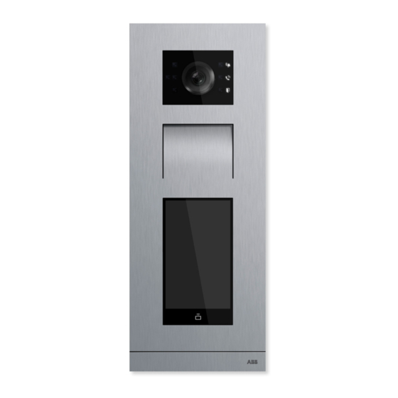
Overview of product range Overview of product range Outdoor stations 2.1.1 Devices ABB-Welcome IP Outdoor stations are installed in the outdoor and indoor areas. The versatility of the devices makes them suitable for the following areas: Building entrances ■ Perimeter areas ■... - Page 16 Overview of product range Article number H8138.T-. H81381P.-. IP pushbutton outdoor Type IP touch 5" outdoor station station Video image 720P 720P Camera angle 139° / 111° / 73° 139° / 111° / 73° diagonal / horizontal / vertical Anti-mist camera ●...
-
Page 17: Installation Boxes
Installation boxes for surface mounting, flush mounting and pre-plastered mounting are not included in the scope of delivery of an outdoor station and must be purchased separately. Abb. 4: Installation boxes for outdoor stations Surface mounting Installation boxes for surface mounting Flush-mounted box for outdoor stations size 1/3, size 1/4, size 1/5, size 2/3 ■... - Page 18 Overview of product range Sizes for the outdoor station installation boxes Outdoor station Size 1 x 5 1 x 4 1 x 3 2 x 3 Installation boxes for surface-mounted installation: Outdoor station 1 x 5 1 x 4 1 x 3 2 x 3 41385.S-xxx 41384.S-xxx...
- Page 19 Overview of product range Installation boxes for flush-mounted installation: Outdoor station Installation box 1 x 5 1 x 4 1 x 3 2 x 3 41385.F-xxx 41384.F-xxx 41383.F-xxx 41386.F-xxx Pre-plastered mounting box 1 x 5 1 x 4 1 x 3 2 x 3 41385.PB-xxx 41384.PB-xxx...
-
Page 20: Individual Assembly Arrangement
Overview of product range 2.1.3 Individual assembly arrangement Aside from the assembled devices, devices can also be arranged individually from single modules. Cover frame 1 x 5 1 x 4 1 x 3 2 x 3 41385CF-x-xx 41384CF-x-xx 41383CF-x-xx 41386CF-x-xx Video and audio modules H851381M-x-xx Doorbell button modules: Round push-buttons... - Page 21 Overview of product range Doorbell button modules: Surface push-buttons 51381SP3-xx 51381SP4-xx End strip modules For: 1x3 / 1x4 / 1x5 For: 2x3 51381EP-x-xx 51382EP-x-xx System Manual │21...
-
Page 22: Indoor Stations Ip Touch 7 And Guard Unit
The integrated blacklist can be used to specify which calls are blocked automatically. For the Guard unit a similar range of functions is available as for the IP Touch 7. The concierge can transfer the call to an IP Touch 7 or assign the access authorisation himself. The ABB- ®... - Page 23 Overview of product range Article Number H82364 H82365 H8303 Type IP Touch 7 IP Touch 7 Guard unit Touchscreen ● ● ● Extension on app without additional system equipment (prerequisite is ● ● ― an Internet connection) Central operating field for DES, CCTV, AC and home automation ●...
-
Page 24: Installation Boxes
Overview of product range 2.2.2 Installation boxes Overview of installation boxes The installation boxes for surface mounting or flush-mounted installation are available separately in the corresponding size for each device. Notice Installation boxes for surface mounting, flush mounting and pre-plastered mounting are not included in the scope of delivery of an indoor station and must be purchased separately. - Page 25 Overview of product range Fig. 6: Installation boxes / Installation box accessories Surface mounting Installation boxes for surface mounting Flush mounting Installation boxes for flush-mounted installation The mounting box for flush-mounted installation is always supplied as a set together with ■...
- Page 26 Overview of product range Installation boxes for surface-mounted installation: Indoor station H82364 IP Touch 7 ■ 42363.S-xxx Installation boxes for flush-mounted installation: Indoor station Installation box plus pre-plastered box mounting box H82364 IP Touch 7 ■ H82365 IP Touch 7 ■...
-
Page 27: System Devices
The management software is installed on the "Smart Access Point". The management software is operated via the indoor station. The "Smart Access Point" offers the access point for commissioning and managing the ABB- Welcome IP with a PC or a mobile terminal device. -
Page 28: Poe Switch Selection
All ABB-Welcome IP devices meet standard IEEE802.3af ■ – ABB-Welcome IP devices can be operated with PoE switches that meet standard 802.3af or 802.3at. A power supply via 24 V is also possible as an alternative to the PoE. The minimum band width amounts to 100 Mbit/s. - Page 29 PoE switch selection Example for the selection of a PoE switch Count Device Power (W) IP Touch 7 32.4 IP touch 5" outdoor station 10.8 Guard unit 2.295 Smart Access Point Pro 10.125 IP actuator 0.81 Total output 56.43 Table 5: Determination of total output of the devices to be connected Result Number of occupied ports: Necessary total output:...
- Page 30 PoE switch selection Devices recommended by ABB Netgear ProSafe series GS108LP GS108PP GS116LP GS116PP 10/100/1000 10/100/1000 10/100/1000 10/100/1000 Mbit/s Mbit/s Mbit/s Mbit/s Speed Gigabit Ethernet Gigabit Ethernet Gigabit Ethernet Gigabit Ethernet Number of ports 8 PoE + ports up 8 PoE + ports up...
-
Page 31: Onsite Devices
Onsite devices Door opener Commercially available door openers with the following key data can be supplied with electrical power via the ABB-Welcome IP switch actuators. 12 V AC/DC, maximum 500 mA ■ For all other commercially available door openers an onsite power supply must be provided. -
Page 32: Connection, Installation / Mounting
Connection, installation / mounting Connection, installation / mounting Outdoor stations: SM installation boxes Notice The device is always installed together with the surface-mounted installation ■ box via a deep standard flush-mounted box. The mounting height of the device and the deep standard flush-mounted box ■... - Page 33 Connection, installation / mounting 3. Attach the surface-mounted installation box. – Fix the surface-mounted installation box on the facade with the aid of the elongated holes. – No additional accessories are necessary for mounting. 4. Mounting the outdoor station. – see chapter 5.3 “Outdoor stations“...
-
Page 34: Outdoor Stations: Fm Installation Boxes And Plastered Boxes
Connection, installation / mounting Outdoor stations: FM installation boxes and plastered boxes 5.2.1 Mounting in insulated facades For mounting the installation boxes in insulated facades, perform the following points: 7 mm Fig. 10: Mounting in insulated facades: Plastered box on device carrier 1. - Page 35 Connection, installation / mounting Fig. 11: Mounting in insulated facades: Inserting flush-mounted installation box 6. After the wall has been plastered, insert the flush-mounted box into the plastered box. – Attention: Ensure that the encircling "Collar" of the flush-mounted installation box rests on the facade.
-
Page 36: Mounting In Clinker Facades
Connection, installation / mounting 5.2.2 Mounting in clinker facades For mounting the installation boxes in clinker facades, perform the following points: Fig. 12: Mounting installation boxes in clinker facades 1. Chisel a hole according to the size of the outdoor station used into the facade provided. –... -
Page 37: Mounting In Hollow Walls
Connection, installation / mounting 5.2.3 Mounting in hollow walls For mounting the installation boxes in hollow walls, perform the following points: 1. Cut a hole according to the size of the outdoor station used into the facade. – The suitable template is enclosed with the flush-mounted installation box. –... - Page 38 Connection, installation / mounting 3. Insert the flush-mounted installation box into the cutout. – Attention: Ensure that the encircling "Collar" of the flush-mounted installation box rests on the facade. The encircling "Collar" of the flush-mounted installation box must not be submerged in the facade.
-
Page 39: Outdoor Stations
Connection, installation / mounting Outdoor stations 5.3.1 Mounting For mounting an outdoor station, perform the following points: 1. First set the installation box for the corresponding mounting situation. – Surface-mounting: see chapter 5.1 “Outdoor stations: SM installation boxes“ on page –... -
Page 40: Dismantling
Connection, installation / mounting Fig. 17: Mounting the outdoor station: Mounting end piece 3. Mounting the end piece. – Attach the end piece on the device slightly offset to the right and press it on. – The spring mechanics in the device pull the end piece auromatically into the correct position when pressed on. -
Page 41: Name Plates
Connection, installation / mounting Fig. 19: Mounting the outdoor station: Pulling the device off 2. Remove the device from the bottom. – Press the device a few mm to the top [1] until it can be pulled off at the bottom [2]. –... -
Page 42: Indoor Stations Ip Touch: Sm Installation Boxes
Connection, installation / mounting Indoor stations IP touch: SM installation boxes Notice The device is always installed together with the surface-mounted installation ■ box via a deep standard flush-mounted box. The mounting height of the device and the deep standard flush-mounted box ■... - Page 43 Connection, installation / mounting 3. Attach the surface-mounted installation box. – Fix the surface-mounted installation box on the facade. – No additional accessories are necessary for mounting. 4. Mounting the indoor station. – see chapter 5.6.1 “Wall installation in installation boxes“ on page 49. System Manual │43...
-
Page 44: Indoor Stations Ip Touch: Fm Installation Boxes And Plastered Boxes
Connection, installation / mounting Indoor stations IP touch: FM installation boxes and plastered boxes 5.5.1 Mounting in solid walls For mounting the installation boxes in solid walls, perform the following points: 7 mm Fig. 23: Mounting installation boxes in solid walls: Plastered box 1. - Page 45 Connection, installation / mounting Fig. 24: Mounting installation boxes in solid walls: Wall work 3. After the plastering / painting work is concluded, remove the protective cover. – After the plastering / painting work is concluded, the wall may only project a maximum of 7 mm over the plastered box.
- Page 46 Connection, installation / mounting 5. Mounting the IP touch indoor station. – see chapter 5.6.1 “Wall installation in installation boxes“ on page 49. System Manual │46...
-
Page 47: Mounting In Hollow Walls
Connection, installation / mounting 5.5.2 Mounting in hollow walls For mounting the installation boxes in hollow walls, perform the following points: 1. Cut a hole according to the size of the indoor station used into the facade. – The suitable template is enclosed with the flush-mounted installation box. –... - Page 48 Connection, installation / mounting Fig. 28: Mounting installation boxes in hollow wall: Inserting flush-mounted installation box 4. Insert the flush-mounted installation box into the cutout. – Attention: Ensure that the encircling "Collar" of the flush-mounted installation box rests on the facade.
-
Page 49: Indoor Stations Ip Touch
Connection, installation / mounting Indoor stations IP touch 5.6.1 Wall installation in installation boxes Notice Due to the larger device depth the IP touch (LAN / LAN) indoor station can ■ only be inserted into a flush-mounted installation box. The additional device versions can be inserted into a surface-mounted ■... - Page 50 Connection, installation / mounting 2. When the installation box is set: Establish the connection on the device. ■ Mount the device into the installation box. ■ – Push the device into the lateral holders of the installation box and press down. System Manual │50...
- Page 51 Connection, installation / mounting 5.6.2 Table installation Notice Due to the larger device depth the IP touch (LAN / LAN) indoor station can ■ only be inserted into a flush-mounted installation box. The additional device versions can be inserted into a table stand. ■...
-
Page 52: Guard Unit
Connection, installation / mounting Guard unit 5.7.1 Wall mounting Notice The device is always installed together with the surface-mounted installation ■ box via a deep standard flush-mounted box. The mounting height of the device and the deep standard flush-mounted box ■... - Page 53 Connection, installation / mounting Fig. 34: Wall mounting of the Guard unit Wall mounting is possible. For this, attach appropriate mounting devices at the installation site that match the holders on the rear of the device. System Manual │53...
- Page 54 Connection, installation / mounting 5.7.2 Table installation The table stand is included with the device and must not be purchased separately. Fig. 35: Table installation of Guard unit System Manual │54...
-
Page 55: Installation Recommendation
Connection, installation / mounting Installation recommendation Network cables must be used for the structured cabling because they are more inflexible due to their mechanical strength than patch cables. For the connection inside the device box it is therefore recommended to install an RJ45 universal module (0219-101-500) to the incoming network cable. -
Page 56: Dimensional Drawings
Connection, installation / mounting Dimensional drawings 5.9.1 Outdoor stations 17,6 17,6 1 x 3 1 x 4 17,6 17,6 1 x 5 2 x 3 Fig. 37: Exterior dimensions of outdoor stations (dimensions in mm) 5.9.2 Indoor stations IP touch 17,0 30,0 198,5... -
Page 57: Installation Boxes - Surface Mounting
Connection, installation / mounting 5.9.3 Installation boxes - Surface mounting 1 x 3 1 x 4 1 x 5 2 x 3 Fig. 39: Dimensions of surface-mounted installation boxes of outdoor stations (dimensions in mm) 1 x 5 1 x 3 1 x 4 2 x 3 Fig. - Page 58 Connection, installation / mounting 17,0 198,5 170,8 Fig. 41: Boreholes and dimensions of surface-mounted installation boxes of indoor stations IP Touch 7 (dimensions in System Manual │58...
-
Page 59: Installation Boxes - Flush-Mounted Installation
Connection, installation / mounting 5.9.4 Installation boxes - flush-mounted installation 1 x 3 1 x 4 1 x 5 2 x 3 Fig. 42: Dimensions of flush-mounted installation boxes of outdoor stations (dimensions in mm) 1 x 5 1 x 3 1 x 4 2 x 3 Fig. - Page 60 Connection, installation / mounting 195,6 50,4 186,6 48,8 56,0 Fig. 44: Dimensions of flush-mounted installation boxes of indoor stations IP Touch 7 (dimensions in mm) System Manual │60...
-
Page 61: Plastered Boxes
Connection, installation / mounting 5.9.5 Plastered boxes 1 x 3 1 x 4 1 x 5 2 x 3 Fig. 45: Installation dimensions of plastered boxes of outdoor stations (dimensions in mm) Fig. 46: Installation dimensions of plastered boxes of indoor stations IP Touch 7 (dimensions in mm) System Manual │61... -
Page 62: Commissioning
Commissioning Commissioning Overview of commissioning Commissioning in three sections Commissioning of the ABB-Welcome IP system is carried out in three sections. – Please observe the order of the steps. They are dependent on each other. Step Local addressing see chapter 6.2 “Commissioning of a system —... -
Page 63: Commissioning Of A System - Step 1: Local Addressing
Commissioning Commissioning of a system — Step 1: Local addressing 6.2.1 Fundamentals of physical addressing ABB-Welcome IP Physical address: Not to be mixed up with the IP address. – The physical address designates the location in the structure of the building. - Page 64 Commissioning Building 1 Perimeter (parking garage) outdoor station Building 2 Setup of the physical address Buildings Storey / Floor Unit (office, private apartment, etc.) Device in a unit System Manual │64...
- Page 65 Commissioning The physical address of a device is principally the same for all devices. The address consists of 4 parts. Part 1 designates the building, part 2 the storey/floor, part 3 the unit on a storey and part 4 the device in a unit. When buildings, floors or units are added, the address for the devices is counted upwards.
- Page 66 From a physical address a ABB-Welcome IP participant generates itself an own IP address (IPv4) in the IP address range 10.x.x.x / 255.x.x.x A physical address is specific in a ABB-Welcome IP system and must not be assigned twice within a device category.
-
Page 67: Physical Addresses - Preparing Addressing
Commissioning 6.2.2 Physical addresses ― Preparing addressing If the devices have a display, the addressing is carried out on the device itself. If the devices do not have a display, the addressing is carried out via the IP Touch 7. Devices with display –... -
Page 68: Indoor Stations Ip Touch 7 And Guard Unit
Commissioning 6.2.3 Indoor stations IP Touch 7 and Guard unit First address stations IP Touch 7 or Guard unit. Addressing is carried out in the same way for all versions. Fig. 48: Addressing station IP Touch 7 or Guard unit The wizard is displayed after the device has booted up automatically and will guide you through the first setup. - Page 69 Commissioning Mode selection and device number: ■ – The first indoor station in each unit is set up as "Master mode" under "Mode selection". The device number of the physical address is then automatically "01" and cannot be set. – Each further indoor station within a unit is set up as "Master mode"...
-
Page 70: Outdoor Station With Display
Commissioning 6.2.4 Outdoor station with display Fig. 49: Outdoor station with display: Settings The wizard is displayed after the device has booted up automatically and will guide you through the first setup. If the device has already been setup, the main menu is displayed directly. To address the device, perform the following steps: 1. - Page 71 Commissioning 5. Open the "Settings" / "Device characteristics" function. 6. In the area "Device characteristics" assign the physical address of the device. – The physical address 001-01 has already been preset in the factory settings. – A preset address or one that has already been entered cannot be confirmed again. In this case, change back to the main menu.
- Page 72 Commissioning Notice The engineering password must be changed the first time you access the engineering settings. – The basic setting is 345678. – This password should only be used for the first setup and changed to a different password. It cannot be used as actual password. Notice If a wrong engineering password is entered 10 times within 5 minutes, no further tries are possible for the next 5 minutes.
- Page 73 Commissioning Operating mode If an outdoor station is to be set up or added for a perimeter (e.g. park house), it is commissioned as normal, just like every other outdoor station. The outdoor station operation for the perimeter is different only in the operating mode and the physical address.
- Page 74 Commissioning 2. Set the physical address for a gate station. A gate station only has the physical address of the device, see chapter 6.2 “Commissioning of a system — Step 1: Local addressing “ on page 63. – Address range: 01 - 32 System Manual │74...
- Page 75 Commissioning Concierge call If a Guard unit is used in the system, the call to the "Guard unit" can be enabled in the outdoor stations. This function can only be used by the outdoor station and the gate station of a building. This ■...
- Page 76 Commissioning 2. Set the concierge call to "ON" and select the physical address of the desired "Guard unit". – Address range: 01 - 32 If the concierge call is enabled, an additional option can be set. – Always transfer each unit call (via the name list or number) to the concierge. –...
-
Page 77: Outdoor Station With Push-Buttons
Commissioning 6.2.5 Outdoor station with push-buttons Address the device via the " IP Touch 7". Fig. 52: Outdoor station with buttons: Commissioning mode To address the device, perform the following steps: 1. Boot up the device. – The device boots up automatically when the power supply is connected. –... - Page 78 Commissioning Fig. 53: Outdoor station without buttons: Addressing via indoor station 4. Switch to menu "System / Settings" at the indoor station. – Switch to function "Outdoor station setting". – The outdoor station is searched for automatically. 5. Address the outdoor station and save the entries via the "OK" button. –...
- Page 79 OS: Outdoor station (Outdoor Station) ■ 2. Set the physical address for a gate station. A gate station only has the physical address of the device, see chapter 6.2.1 “Fundamentals of physical addressing ABB-Welcome IP“ on page 63. – Address range: 01 - 32 System Manual │79...
- Page 80 1. Enable the "Outdoor station setting / "Concierge call forward" function on the indoor station. 2. Set the physical address for a gate station. A gate station only has the physical address of the device, see chapter 6.2.1 “Fundamentals of physical addressing ABB-Welcome IP“ on page 63.
-
Page 81: Ip Switch Actuator
Commissioning 6.2.6 IP switch actuator Address the device via the " IP Touch 7" Fig. 56: IP switch actuator: commissioning mode To address the device, perform the following steps: 1. Boot up the device. – The device boots up automatically when the power supply is connected. –... - Page 82 Commissioning Fig. 57: Addressing IP switch actuator 4. Switch to menu "System / Settings" at the indoor station. – Switch to function "IP switch actuator setting". – The IP switch actuator is searched for automatically. – Select the operating mode of the IP switch actuator. –...
-
Page 83: Commissioning Of A System - Step 2: Commissioning "Smart Access Point
Commissioning Commissioning of a system — Step 2: Commissioning "Smart Access Point" 6.3.1 Overview Commissioning of the "Smart Access Point" system is carried out in 3 sections. – Please observe the order of the steps. They are dependent on each other. Connect the "Smart Access Point"... - Page 84 Commissioning Fig. 59: LAN cable on the "Smart Access Point" Use the following steps to boot up the "Smart Access Point": 1. Connect the LAN cable with the "Smart Access Point". 2. Remount the cover of the "Smart Access Point". –...
- Page 85 Commissioning Connecting the "Smart Access Point" with the PC via WLAN Use the following steps to connect with the PC: Fig. 60: WLAN access data 1. Note down the WLAN access data. – The WLAN access data are located on the device. Remove the cover of the device. Fig.
- Page 86 Commissioning Fig. 63: Start page of the "Smart Access Point" – The start page of the "Smart Access Point" is displayed in the browser. – During the first call-up the start page is in English. System Manual │86...
-
Page 87: Preliminary Information: Selection Of The System Mode
Commissioning 6.3.3 Preliminary information: Selection of the system mode Preliminary information about the selection of the system modes Fig. 64: Preliminary information about the selection of the system modes The graphics illustrate two basic areas within buildings (here a residential building). Both areas of the installation are strictly separated by the first indoor station (master) of a unit which operates as IP gateway. - Page 88 – The "Smart Access Point" has the static IP address "10.0.0.1". – The 10s IP address range is used to communicate with the "ABB-Welcome IP" participants. – In parallel the "Smart Access Point" can be connected with a router per WLAN or LAN and act as DHCP Client.
-
Page 89: Commissioning The "Smart Access Point
Commissioning 6.3.4 Commissioning the "Smart Access Point" When the "Smart Access Point" is connected to the PC and the start page of the "Smart Access Point" is called up in the browser, the "Smart Access Point" is ready for commissioning. During commissioning a wizard guides through the individual steps. - Page 90 Commissioning 2. Accept the following licence agreements: End-user licence agreement ■ Software licence agreement ■ Data protection declaration ■ Fig. 67: Commissioning "Smart Access Point": Building type 3. Select the building type (system mode). – Detailed information: see chapter 6.3.3 “Preliminary information: Selection of the system mode“...
- Page 91 Commissioning 4. Enter the location. – A time zone can be selected from a drop-down menu. – This step can be skipped. During the later reconnection there is an automatic request for an adjustment if the values between the PC and the "Smart Access Point" do not match. System Manual │91...
- Page 92 Commissioning Fig . 69: Commissioning "Smart Access Point": WIFI settings 5. Entering the WIFI settings of the "Smart Access Point". SSID (Name): ■ – The name can be freely selected. This can, for example, be the name of the device (located on the device) or the name of the building in which the "Smart Access Point"...
- Page 93 6. Connection to the local network – Attention! Do not skip this step if devices are to be integrated now or later into the ABB- Welcome IP. For the application of the "Smart Access Point" in the "ABB-Welcome IP" system a selection of the type of connection is absolutely necessary.
- Page 94 All communication with system devices of the ABB-Welcome IP is carried out via a ■ LAN interface. All system devices of the ABB-Welcome IP keep their own IP address when they are ■ used in the building network. The "Smart Access Point" can reach them even if they use a DHCP client IP address.
- Page 95 Commissioning Fig. 71: Commissioning "Smart Access Point": LAN Network settings 7. Network settings – If a LAN connection was selected, the IP address must be specified to establish the LAN connection. Checkbox "Obtain IP address automatically' is activated: ■ – The "Smart Access Point"...
- Page 96 Commissioning – If a WLAN connection is selected, a connection with a WLAN network must be established. – All available nearby WLAN networks will be displayed on the list. – If you can’t find the desired WLAN network, click the "Update" button to search again.
- Page 97 Commissioning 9. Options for resetting the "Smart Access Point". Without MyBuildings account ■ – If this option is selected, anyone can reset the password for the first admin user by pressing the reset button. – This configuration is used when the "Smart Access Point" is installed in a private area and is not physically accessible to unauthorized users.
- Page 98 Commissioning [2] The myBuildings portal is called up via the "Register" link. There an account can be registered if necessary. [3] Enter the user name, the password and the display name. Then click on "Connect". A connection with the MyBuildings portal is established. [4] If access is to be gained to the "Smart Access Point"...
- Page 99 Commissioning Fig. 77: Commissioning "Smart Access Point": Device name 11. Define an unmistakable device name. – The UPnP device name is defined with the device name. – The device name will be displayed on the log in screen. Fig. 78: Commissioning "Smart Access Point": Overview of settings 12.
- Page 100 Commissioning Fig . 79: Commissioning "Smart Access Point": Confirm settings 13. Confirm the settings made. – The system configures itself. Fig . 80: Commissioning "Smart Access Point": Confirm commissioning 14. Confirm the configuration. System Manual │100...
- Page 101 Commissioning Fig. 81: Commissioning "Smart Access Point": Separation of connection – At the end of initial commissioning the "Smart Access Point" switches automatically into the Access-Point mode (the LED lights up red). – The WLAN connection with the "Smart Access Point" is activated with the new data. –...
-
Page 102: Commissioning A System - Step 3: Searching And Certifying
6.4.2 “Preliminary ■ enter the IP address of the PC in the IP address range of information: Adjusting IP addresses the ABB-Welcome IP system. to a PC“ on page 103 see chapter 6.4.4 “Adding via ■ automatic search“ on page 108 Searching and certifying devices. -
Page 103: Preliminary Information: Adjusting Ip Addresses To A Pc
Commissioning 6.4.2 Preliminary information: Adjusting IP addresses to a PC Depending on the setup of the system, the IP address of the connection must be put on the same area on the PC / laptop as that of the device (only required once). Otherwise the Web browser does not establish a connection to the device. - Page 104 Commissioning Use the following steps to set the IP address: 1. Switch to the system controller. 2. Open: The network and the enabling centre. – "Network and Internet" / "Network and enabling centre". 3. Open: "Changing the adapter settings" [1]. –...
-
Page 105: Reconnect The "Smart Access Point
The "Smart Access Point" always has the fixed IP address "10.0.0.1". This address is necessary to communicate with the ABB-Welcome IP in the IP network. If a router with DHCP function is active in the same network, the "Smart Access Point" operates in parallel as DHCP client. This means that, if necessary, the router can be checked to see which IP address the "Smart Access... - Page 106 Commissioning Connect. Use the following steps to connect with the PC: 1. Connecting the PC with the LAN of the "Smart Access Point". Fig. 84: Entering the IP address of the "Smart Access Point" in a browser 2. Call up the start page of the "Smart Access Point" in a commercially available browser. [A} There is no router with a DHCP function in the system.
- Page 107 Commissioning Fig. 86: Start page of the "Smart Access Point" – The start page of the "Smart Access Point" is displayed. System Manual │107...
-
Page 108: Adding Via Automatic Search
Commissioning 6.4.4 Adding via automatic search For the certification of devices, first the entire system is searched in the "Smart Access Point" for available devices. Fig. 87: Door communication: Searching and certifying Use the following steps to search for devices automatically: 1. - Page 109 Commissioning Fig. 88: Door communication: Search run 3. Start the "Searching and certifying" function [1] in the door communication of the "Smart Access Point". – All located devices are displayed. – The search always extends itself over the entire available address range of the door communication system.
-
Page 110: Defining Trustworthy Devices
Commissioning 6.4.5 Defining trustworthy devices Outdoor stations, indoor station and the IP switch actuators must be joined to each other. This specifies the indoor station from which the door is allowed to be opened. Fig. 89: Joining device together To join the devices, perform the following steps: 1. -
Page 111: Backup / Restore The Project
Commissioning 6.4.6 Backup / restore the project Fig. 90: Data backup / data restoration Create the first data backup after the first initialization has been completed. Then create a backup after every major change, such as the addition or deletion of devices. To create the data backup, carry out the following steps: 1. -
Page 112: Adding Devices Manually In The "Smart Access Point
Commissioning Adding devices manually in the "Smart Access Point" Address the device via the " IP Touch 7" Fig. 91: IP switch actuator: commissioning mode To address the device, perform the following steps: 1. Boot up the device. – The device boots up automatically when the power supply is connected. –... - Page 113 Commissioning Fig. 92: Addressing IP switch actuator 4. Switch to menu "System / Settings" at the indoor station. – Switch to function "IP switch actuator setting". – The IP switch actuator is searched for automatically. – Select the operating mode of the IP switch actuator. –...
- Page 114 Commissioning Adding device manually Fig. 93: Adding device manually: Example of IP switch actuator Use the following steps to add devices manually: 1. Connect a PC with the "Smart Access Point". – More detailed information for connecting, see chapter 6.4.3 “Reconnect the "Smart Access Point"“...
- Page 115 Commissioning 2. The outdoor station has two door opening contacts. In the device management on the page of the outdoor station make the following settings for the first door opening contact: – Main door opener: IP switch actuator – Mode: Door opener contact –...
-
Page 116: Delete Device In The "Smart Access Point
Commissioning Delete device in the "Smart Access Point" Fig. 94: Deleting devices One device or several devices can be deleted at the same time. They are deleted in the device administration of the "Smart Access Point". Carry out the following steps to delete devices: 1. -
Page 117: Reset (Reset System / Devices)
Commissioning RESET (Reset system / devices) 6.7.1 Indoor stations IP Touch 7 and Guard unit Fig. 95: Resetting the indoor stations IP Touch 7 and Guard unit Resetting becomes necessary, for example, when they have already been integrated in a system or are to be integrated in a new system. -
Page 118: Outdoor Station With Buttons / Display
Commissioning 6.7.2 Outdoor station with buttons / display Resetting becomes necessary, for example, when they have already been integrated in a system or are to be integrated in a new system. Carry out the following steps to reset devices: 1. Briefly interrupt the power supply at the rear of the device. –... -
Page 119: Ip Switch Actuator
Commissioning 6.7.3 IP switch actuator Fig. 96: Resetting the IP actuator Resetting becomes necessary, for example, when they have already been integrated in a system or are to be integrated in a new system. Carry out the following steps to reset devices: 1. -
Page 120: Smart Access Point
Commissioning 6.7.4 "Smart Access Point" Completely resetting the "Smart Access Point". – Here all entered data, performed settings, etc., are deleted. After the reset the "Smart Access Point" will be in the state at the point of delivery. – After the reset, an initial commissioning of the "Smart Access Point" must be carried out. –... - Page 121 Commissioning Resetting the password of the 1st administrator. The reset depends on the option of resetting that was selected for the commissioning of the "Smart Access Point". Option "Without MyBuildings account": ■ – The password of the 1st administrator is reset on the rear side of the "Smart Access Point"...
-
Page 122: Setting Up The Doorbell Buttons Of The "Ip Pushbutton Outdoor Station
Commissioning Setting up the doorbell buttons of the "IP pushbutton outdoor station" The doorbell buttons of the outdoor station must be assigned to the respective indoor stations that they are to activate. The happens via the assigning of the physical addresses of the indoor stations to the respective doorbell button. - Page 123 Commissioning Fig. 99: Outdoor station with buttons: Assembling the doorbell buttons 4. Switch to menu "System / Settings" at the indoor station. – Switch to function "Outdoor station setting". – The outdoor station is searched for automatically. 5. Change to the "Enter push-button address“ function. –...
-
Page 124: Setting Up Name Entries In The Ip Touch 5" Outdoor Station
Commissioning Setting up name entries in the IP touch 5" outdoor station 6.9.1 Introduction The name entries must be added or changed for the outdoor stations with display after the actual commissioning of the system or later during the running operation. This can be performed centrally and easily via the "Smart Access Point". - Page 125 Commissioning Fig. 100: Name entries of the indoor station: Selecting the indoor station 1. Change to the indoor stations and select the desired indoor station. Fig. 101: Name entries of the indoor station: Name assignment function 2. Change to the name assignment function for the indoor station. System Manual │125...
- Page 126 Commissioning Fig. 102: Name entries of the indoor station: Entering the names 3. Enter the names. 4. Confirm the entries made. In this way consecutively select and rename each indoor station. When all desired indoor stations are named, then continue with the import of these names in the outdoor station. System Manual │126...
- Page 127 Commissioning Step 2: Importing the name list / placeholder list into the outdoor station with display. Are the indoor stations already named (step 1), these names are imported as name entries. ■ Are the names still unknown, placeholders are imported as name entries. These can be ■...
- Page 128 Commissioning Fig. 105: Adding names: Select outdoor station 4. Select all relevant indoor stations in the building structure. – Are the names still unknown, the system names of the indoor station are displayed here (e.g.: "Indoor station 001-0202-01"). 5. Import the selection. Fig.
-
Page 129: Changing Name Entries
Commissioning 6.9.3 Changing name entries The change of a name entry is not transmitted automatically to all linked devices. The name entry is changed in three main steps: Change the entry of the indoor station. ■ Delete the old entry in the outdoor station. ■... - Page 130 Commissioning Fig. 108: Changing name: Name assignment of indoor function 2. Change to the name assignment function for the indoor station. Fig. 109: Changing name: Overwriting the indoor station name 3. Enter the new name. – For this, overwrite the old name. 4.
- Page 131 Commissioning Fig. 110: Changing name: Select outdoor station 1. Change to the desired outdoor station or select several outdoor stations in a multiple selection. Fig. 111: Changing name: Select outdoor station entry from the name list 2. Change to the "Name list" function. 3.
- Page 132 Commissioning Fig. 112: Changing name: Delete outdoor station entry from the name list 4. Delete the old entry and confirm the action. Importing the new entry into the outdoor station Fig. 113: Changing name: Outdoor station function "Select device" 5. Change to the "Select devices" function. –...
- Page 133 Commissioning Fig. 114: Changing name: Select renamed indoor station from device list 6. Select the newly named indoor station in the building structure. 7. Import the selection. Fig. 115: Changing name: Entry is changed – The entry is changed. Notice If the displayed entries on several outdoor stations are the same, a multiple ■...
-
Page 134: Several Name Entries For A Ip Touch 7
Commissioning 6.9.4 Several name entries for a IP Touch 7 For each resident (owner, tenant, office, etc.) several name entries of the associated indoor station can be created. These are shown accordingly on the display of the outdoor station. To add the additional name entries, perform the following steps: 1. - Page 135 Commissioning Fig. 118: Additional name entry: Select indoor station 7. Select the desired indoor station and confirm the selection. Fig. 119: Additional name entry: Enter new data – The current data are displayed in the "Resident / Tenant" area. 8. Overwrite the data in the "Resident / Tenant“ area with the new entries. –...
- Page 136 Commissioning Fig. 120: Additional name entry: New name entry is added – The new entry is added as additional name entry for a resident / Tenant. System Manual │136...
-
Page 137: Change Devices / Change Physical Address
Commissioning 6.10 Change devices / Change physical address The devices can be changed later at any time. This, for example, could be necessary when when after the installation an indoor station "moves" to a different floor or house. This also applies when a device is to be commissioned that has already been commissioned in a different system. -
Page 138: Case Studies
Case studies Case studies Legend Legends in the graphics: Outdoor station: IP pushbutton outdoor station Outdoor station: IP touch 5" outdoor station Smart Access Point: Smart Access Point Lite Indoor station: IP Touch 7 Indoor station: Guard unit IP actuator: IP actuator Switch: Commercially available... -
Page 139: Private Apartment
■ Switch (PoE-capable) ■ In a ABB-Welcome IP system the devices are integrated and managed via the "Smart Access Point". The "Smart Access Point" is therefore a prerequisite for the operation. Fig. 121: Overview: Minimum installation (Switch with PoE) Fig. 122: Connection: Minimum installation (Switch with PoE) System Manual │139... - Page 140 Case studies Unit (Switch without PoE): The switch is not PoE-capable in a system or the capacity is too low. That is why an additional power supply is required for the devices. 24 V DC Fig. 123: Overview: Unit (Switch without PoE) 100 - 240 V 24 V Fig.
- Page 141 Case studies Unit with door opener: The entrance door is equipped with a door opener. For this an IP switch actuator is required which accepts the digital opening command and switches the door opener. Fig. 125: Overview: Unit with door opener Fig.
- Page 142 Case studies Unit with three indoor stations: If further indoor stations are added to a unit, this is a special feature. These additional indoor stations are separated from the remaining devices and constitute an independent network. At the end of the installation there is the building network and the units network (with the additional indoor stations).
- Page 143 Case studies Fig. 128: Connection: Unit with several indoor stations System Manual │143...
-
Page 144: Adding A Unit Network / Indoor Stations To A Unit
Case studies Adding a unit network / indoor stations to a unit 7.3.1 Introduction P E o Fig. 129: Overview: Connecting additional indoor stations If a one or several indoor stations are to be added in a unit (apartment, office, etc.), these constitute an independent network. - Page 145 Case studies Depending on the situation and the selected version, 4 basic options are to be considered for the connection. Point to point connection (1st indoor station LAN / 2nd indoor station LAN), see chapter ■ 7.3.2 “Point-Point connection / LAN-LAN“ on page 146. PoE switch connection (1st indoor station LAN / 2nd indoor station LAN), see chapter 7.3.3 ■...
-
Page 146: Point-Point Connection / Lan-Lan
Case studies 7.3.2 Point-Point connection / LAN-LAN LAN 1 LAN 2 LAN 1 Master 24 V DC Fig. 130: Adding a units network point-point / LAN-LAN This version allows an additional indoor station to be added in a unit as extension unit. The second LAN connection of an indoor station is not PoE-capable. - Page 147 Case studies 4. Prepare the home network. For this, set up the LAN connections of the additional indoor stations (extension units) in ■ the "Local settings" / "Home network port". – LAN/WLAN version: Set it on "LAN". – LAN/LAN version: Set it on the 1st LAN connection "LAN1". 5.
-
Page 148: Connection Of Poe Switch / Lan-Lan
Case studies 7.3.3 Connection of PoE switch / LAN-LAN LAN 1 LAN 2 Master Fig. 132: Adding a units network PoE switch / LAN-LAN This version allows up to 7 additional indoor stations (02 - 08) to be added in a unit as extension units. - Page 149 Case studies 4. Prepare the home network. For this, set up the LAN connections of the additional indoor stations (extension units) in ■ the "Local settings" / "Home network port". – LAN/WLAN version: Set it on "LAN". – LAN/LAN version: Set it on the 1st LAN connection "LAN1". 5.
-
Page 150: Connection Of Router / Lan-Lan
Set the following points in the "Local settings" function: Physical address (physical address, see chapter 6.2.1 “Fundamentals of physical ■ addressing ABB-Welcome IP“ on page 63). Apart from the device number the physical address of the extension unit is identical with the master address. - Page 151 Case studies 3. Prepare the home network. For this, set up the LAN connections of the additional indoor stations (extension units) in ■ the "Local settings" / "Home network port". – LAN/WLAN version: Set it on LAN. – LAN/LAN version: Set it on the 1st LAN connection "LAN1". Change to the "Smart Access Point".
-
Page 152: Connection Of Router / Wlan-Wlan
Case studies 7.3.5 Connection of router / WLAN-WLAN LAN 1 WLAN DHCP Master 24 V DC Fig. 136: Adding a unit network router / WLAN-WLAN This version allows up to 7 additional indoor stations (02 - 08) to be added in a unit as extension unit. - Page 153 Case studies 3. Set up the WLAN connection. – Perform the following points in menu "Network settings / WIFI settings": Scan and select the network. ■ Set up a network password with WLAN. ■ Change to the "Smart Access Point". 4.
-
Page 154: Practice-Oriented Examples
Practice-oriented examples 7.4.1 One-family house with a panel In a ABB-Welcome IP system in a private building the building network is disconnected from the units network. This prevents unauthorized access to the private units network via the outdoor station. A IP Touch 7 is installed. - Page 155 Case studies Fig. 140: Physical addressing: One-family house with one panel The counting sequence of the physical addresses can be freely selected. However, it should be noted that no physical address can be assigned twice to a device type. This would cause conflict.
-
Page 156: One-Family House With Three Panels
Case studies 7.4.2 One-family house with three panels In a ABB-Welcome IP system in a private building the building network is disconnected from the units network. This prevents unauthorized access to the private units network via the outdoor station. Three IP Touch 7 devices are installed. - Page 157 Case studies Fig. 142: Connection: One-family house with three panels Fig. 143: Physical addressing: One-family house with three panels The counting sequence of the physical addresses can be freely selected. However, it should be noted that no physical address can be assigned twice to a device type. This would cause System Manual │157...
- Page 158 Case studies conflict. Physical Address Settings Building No. Floor No. Units No. Device ID Mode ― ― ― Master Subsidiary mode Subsidiary mode One-family house ― ― ― ― / Terraced house Table 9: Physical addressing: One-family house with three panels System Manual │158...
-
Page 159: Multifamily House With 10 Parties
7.4.3 Multifamily house with 10 parties In a ABB-Welcome IP system an IP Touch 7 is installed in a multifamily house for every unit. One outdoor station each is installed for the building entrances. One IP switch actuator each is required for the door openers. - Page 160 Case studies Fig. 145: Connection: Multifamily house with 10 parties System Manual │160...
- Page 161 Case studies Fig. 146: Physical addressing: Multifamily house with 10 parties The counting sequence of the physical addresses can be freely selected. However, it should be noted that no physical address can be assigned twice to a device type. This would cause conflict.
- Page 162 Case studies Outdoor station / ― ― ― Master / ― Master / ― Master / ― Master / ― Master / ― Master / ― Master / ― Master / ― Master / ― Master / ― Table 10: Physical addressing: Multifamily house with 10 parties System Manual │162...
-
Page 163: Multifamily House With A Floor Door In A Separate Building Wing
Multifamily house with a floor door in a separate building wing In a ABB-Welcome IP system an IP Touch 7 is installed in a multifamily house for every unit. One outdoor station is installed for the building entrance. One IP switch actuator is installed for the door opener of this entrance. - Page 164 Case studies Fig. 148: Connection: Multifamily house with entrance door in the separate wing System Manual │164...
- Page 165 Case studies Fig. 149: Physical addressing: Multifamily house with entrance door in the separate wing The counting sequence of the physical addresses can be freely selected. However, it should be noted that no physical address can be assigned twice to a device type. This would cause conflict.
- Page 166 Case studies ― / Building IP ― ― actuator Master / ― Master / ― Master / ― Master / ― Master / ― Master / ― Master / ― Master / ― Table 11: Physical addressing: Multifamily house with entrance door in the separate wing System Manual │166...
-
Page 167: Multifamily House With Units Doors
7.4.5 Multifamily house with units doors In a ABB-Welcome IP system an IP Touch 7 is installed in a multifamily house for every unit. Each unit additionally receives an outdoor station for the units entrance door and an IP switch actuator for the automatic door opener. - Page 168 Case studies Fig. 151: Connection: Multifamily house with outdoor station for each unit System Manual │168...
- Page 169 Case studies Fig. 152: Physical addressing: Multifamily house with outdoor station for each unit The counting sequence of the physical addresses can be freely selected. However, it should be noted that no physical address can be assigned twice to a device type. This would cause conflict.
- Page 170 Case studies ― ― ― / Bulding IP actuator ― / ― Multi-unit house / commercial / ― / ― ― ― ― ― / ― ― ― ― / Bulding IP actuator ― / ― ― ― Outdoor station / ― / ― / ― ―...
-
Page 171: One-Family House With Camera
One-family house with camera Notice Commercially available IP cameras with the profile "ONVIF Profile S" and the video coding format "H.264" can be integrated in the ABB-Welcome IP system. The IP camera can be connected to the router as DHCP client. LAN1... - Page 172 Abb. 155: Credentials of the IP camera in the "Smart Access Point" 2. Then click "Enter credentials". Abb. 156: Enter the credentials of the IP camera in the "Smart Access Point" 3. Enter the user name and the password of the IP camera and click on "Pair".
- Page 173 Case studies Fig. 158: Start screen in the IP Touch 7: IP cameras – Click on the "Search" button to search for the IP cameras and to create a camera list automatically. Select an IP camera from the camera list and click on the "Start" button. –...
-
Page 174: Multifamily House With 10 Parties And Camera
Notice Commercially available IP cameras with the profile "ONVIF Profile S" and the video coding format "H.264" can be integrated in the ABB-Welcome IP system. The IP camera must be integrated in the IP address range 10.0.3.1 - 10.0.3.254. Fig. 159: Multifamily house with camera Setting up the IP camera in the Smart Access Point. - Page 175 Abb. 161: Credentials of the IP camera in the "Smart Access Point" 2. Then click "Enter credentials". Abb. 162: Enter the credentials of the IP camera in the "Smart Access Point" 3. Enter the user name and the password of the IP camera and click on "Pair".
- Page 176 Case studies Integrating the IP camera in the IP Touch 7 Fig. 163: Community Monitor in the IP Touch 7 4. In the IP Touch 7 change to "System settings" / "Monitor settings" and there open the "Community monitor" page. Fig.
-
Page 177: One-Family House With Abb-Welcome Ip And Free@Home
In a ABB-Welcome IP system in a private building the ABB-Welcome IP system is connected with a free@home system. After the connection there is the option of operating the ABB- Welcome IP system via the free@home system. For example, to accept a door call on a free@home panel. - Page 178 Fig. 167: Password on the IP Touch 7 2. Enter the user name and password, and click on "OK". free@home: ABB-free@homeTouch 4.3": Fig. 168: Start page ABB-free@homeTouch 4.3" 3. The start page of free@home is set on "SysAP". Additional details are available in the product manual.
-
Page 179: One-Family House With Abb-Welcome ® App
Case studies 7.4.9 One-family house with ABB-Welcome ® The ABB-Welcome IP system is to be operated additionally with a mobile device (smartphone, etc.) via the ABB-Welcome ® App. For example, to accept a door call. LAN1 LAN2 Router LAN1 ®... - Page 180 Fig. 170: Engineering settings on the IP Touch 7 1. Mode selection = Master mode ® – The connection of the ABB-Welcome App is only possible within a unit/one-family house, and there on the IP Touch 7 with the master mode. 2. Home network port –...
-
Page 181: Perimeter
Case studies Perimeter An installation with a perimeter is illustrated in the following example. The perimeter comprises two houses and associated parking garage. Each unit receives an indoor station. ■ The main entrances and the parking garage receive an outdoor station. ■... - Page 182 Case studies Up-Link Fig. 172: Overview: Perimeters System Manual │182...
- Page 183 Case studies Fig. 173: Connection: Perimeters System Manual │183...
- Page 184 Case studies UP-link connection for the cascading (series switching) of switches: – When the switch has an up-link connection: Connect the up-link connection with a normal LAN cable with a LAN connection of the next switch. – When the switch has no up-link connection: Connect a LAN connection with a crossover cable with a LAN connection of the next switch.
- Page 185 Case studies P E o Up-Link P E o Fig. 174: Physical addresses: Perimeter System Manual │185...
- Page 186 Case studies The counting sequence of the physical addresses can be freely selected. However, it should be noted that no physical address can be assigned twice to a device type. This would cause conflict. Physical Address Settings Mode / Building No. Floor No.
-
Page 187: Glossary
Perimeter Boundary of an administration unit. – A typical example of such a boundary in ABB-Welcome IP is an underground car park to which several houses belong. There is a central access to the underground car park for all and several independent houses. -
Page 188: Notes
Notes Notes System Manual │188... -
Page 189: Index
PoE switch selection ........28 Dismantling ..........40, 41 Point-point connection / LAN-LAN ....145, 146 Ports a services in a ABB-Welcome IP system ..13 Door opener ..........31 Practice-oriented examples ......154 Practice-oriented examples for application ..154 Example of application for private apartment .. - Page 190 Index Table installation ........51, 54 Wall mounting ..........52 Wiring of a ABB-Welcome IP system..... 11 System Manual │190...
- Page 191 Busch-Jaeger Elektro GmbH A member of the ABB Group Freisenbergstraße 2 58513 Lüdenscheid www.BUSCH-JAEGER.com info.bje@de.abb.com Central sales service: Tel.: +49 2351 956-1600 Fax: +49 2351 956-1700 Copyright © 2021 Busch-Jaeger Elektro GmbH All rights reserved...