Siemens SIMOTICS S-1FK2 Configuration Manual
Synchronous motors for sinamics s120
Hide thumbs
Also See for SIMOTICS S-1FK2:
- Configuration manual (122 pages) ,
- Operating instructions manual (118 pages) ,
- Service manual (60 pages)

Related Manuals for Siemens SIMOTICS S-1FK2


Summary of Contents for Siemens SIMOTICS S-1FK2
- Page 1 Edition 02/2022 CONFIGURATION MANUAL SIMOTICS S-1FK2 synchronous motors For SINAMICS S120 www.siemens.com/drives...
- Page 3 Introduction Fundamental safety instructions for the SIMOTICS documentation SIMOTICS Description of the motors Drive technology Mechanical properties 1FK2 Synchronous Motors for SINAMICS S120 Motor components Configuration Manual Configuration Technical data and characteristics Preparation for use Electrical connection Assembly drawings/ dimension sheets Glossary 02/2022 A5E46927724B AD...
- Page 4 Note the following: WARNING Siemens products may only be used for the applications described in the catalog and in the relevant technical documentation. If products and components from other manufacturers are used, these must be recommended or approved by Siemens. Proper transport, storage, installation, assembly, commissioning, operation and maintenance are required to ensure that the products operate safely and without any problems.
-
Page 5: Introduction
More information Information on the following topics is available at: • Additional links to download documents • Using documentation online (find and search in manuals / information) More information (https://support.industry.siemens.com/cs/de/en/view/108998034) 1FK2 Synchronous Motors for SINAMICS S120 Configuration Manual, 02/2022, A5E46927724B AD... - Page 6 Later, you can log on with your login data. You can create your own personal library under "mySupport" using the following procedure. Precondition You have registered for and logged on to "Siemens Industry Online Support", hereinafter referred to as "SIOS". SIOS (https://support.industry.siemens.com/cs/de/en/) Procedure for creating a personal library 1.
- Page 7 Siemens does not control the information on these websites and is not responsible for the content and information provided there. The user bears the risk for their use.
- Page 8 Introduction (e.g. time stamps). If the user links these data with other data (e.g. shift plans) or if he stores person-related data on the same data medium (e.g. hard disk), thus personalizing these data, he has to ensure compliance with the applicable data protection stipulations. 1FK2 Synchronous Motors for SINAMICS S120 Configuration Manual, 02/2022, A5E46927724B AD...
-
Page 9: Table Of Contents
Table of contents Introduction ............................3 Fundamental safety instructions for the SIMOTICS documentation ........... 11 Fundamental safety instructions..................11 1.1.1 General safety instructions ....................11 1.1.2 Equipment damage due to electric fields or electrostatic discharge ........16 1.1.3 Security information ......................16 1.1.4 Residual risks of power drive systems ................. - Page 10 Table of contents Motor components ..........................59 Encoder ..........................59 Holding brake ........................60 4.2.1 Types and modes of operation of the holding brakes ............60 4.2.2 Properties .......................... 61 4.2.3 Technical specifications ...................... 62 Configuration............................65 Configuring software ......................65 5.1.1 SIZER configuration tool ....................
- Page 11 Table of contents 6.3.2.11 1FK2208-4AC ........................118 6.3.2.12 1FK2208-5AC ........................119 6.3.2.13 1FK2210-3AB ........................120 6.3.2.14 1FK2210-3AC ........................121 6.3.2.15 1FK2210-4AB ........................122 6.3.2.16 1FK2210-4AC ........................123 6.3.2.17 1FK2210-5AC ........................124 6.3.3 High Inertia ........................125 6.3.3.1 1FK2306-2AC ........................125 6.3.3.2 1FK2306-4AC ........................
- Page 12 Table of contents 1FK2 Synchronous Motors for SINAMICS S120 Configuration Manual, 02/2022, A5E46927724B AD...
-
Page 13: Fundamental Safety Instructions For The Simotics Documentation
Fundamental safety instructions for the SIMOTICS documentation Fundamental safety instructions 1.1.1 General safety instructions WARNING Electric shock and danger to life due to other energy sources Touching live components can result in death or severe injury. • Only work on electrical devices when you are qualified for this job. •... - Page 14 Fundamental safety instructions for the SIMOTICS documentation 1.1 Fundamental safety instructions WARNING Electric shock due to damaged motors or devices Improper handling of motors or devices can damage them. Hazardous voltages can be present at the enclosure or at exposed components on damaged motors or devices.
- Page 15 • Therefore, if you move closer than 20 cm to the components, be sure to switch off radio devices, cellphones or WLAN devices. • Use the "SIEMENS Industry Online Support app" only on equipment that has already been switched off.
- Page 16 Fundamental safety instructions for the SIMOTICS documentation 1.1 Fundamental safety instructions WARNING Unexpected movement of machines caused by inactive safety functions Inactive or non-adapted safety functions can trigger unexpected machine movements that may result in serious injury or death. • Observe the information in the appropriate product documentation before commissioning. •...
- Page 17 Fundamental safety instructions for the SIMOTICS documentation 1.1 Fundamental safety instructions WARNING Injury caused by moving or ejected parts Contact with moving motor parts or drive output elements and the ejection of loose motor parts (e.g. feather keys) out of the motor enclosure can result in severe injury or death. •...
-
Page 18: Equipment Damage Due To Electric Fields Or Electrostatic Discharge
Siemens’ products and solutions undergo continuous development to make them more secure. Siemens strongly recommends that product updates are applied as soon as they are available and that the latest product versions are used. Use of product versions that are no longer supported, and failure to apply the latest updates may increase customer’s exposure to cyber... -
Page 19: Residual Risks Of Power Drive Systems
Fundamental safety instructions for the SIMOTICS documentation 1.1 Fundamental safety instructions Industrial Security Configuration Manual (https://support.industry.siemens.com/cs/ww/en/ view/108862708) WARNING Unsafe operating states resulting from software manipulation Software manipulations, e.g. viruses, Trojans, or worms, can cause unsafe operating states in your system that may lead to death, serious injury, and property damage. - Page 20 Fundamental safety instructions for the SIMOTICS documentation 1.1 Fundamental safety instructions 3. Hazardous shock voltages caused by, for example: – Component failure – Influence during electrostatic charging – Induction of voltages in moving motors – Operation and/or environmental conditions outside the specification –...
-
Page 21: Description Of The Motors
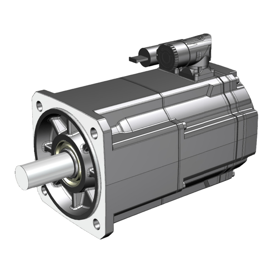
Description of the motors Highlights and benefits Overview The SIMOTICS S-1FK2 servomotors are compact and highly dynamic synchronous motors for a wide range of uses in an industrial environment. They are characterized by high power density, degree of protection and overload capability. -
Page 22: Motors Used For The Intended Purpose
• If you are affected, stay a minimum distance of 30 cm away from the motors (tripping threshold for static magnetic fields of 0.5 mT according to Directive 2013/35/EU). Please contact your local Siemens office in the following cases: • If you wish to use special versions and design variants whose specifications vary from the motors described in this document. - Page 23 Description of the motors 2.2 Motors used for the intended purpose Typical applications Typically, 1FT2 synchronous motors are used in the following applications: • Machine tools (e.g. auxiliary axes, feed drives) • Robots and handling systems • Packaging, plastics and textile machines •...
-
Page 24: Technical Characteristics And Ambient Conditions
Description of the motors 2.3 Technical characteristics and ambient conditions Technical characteristics and ambient conditions 2.3.1 Directives and standards Standards that are complied with Note The standards listed in this manual are not dated. You can take the currently relevant and valid dates from the Declaration of Conformity. The motors of the type series SIMOTICS S, SIMOTICS M, SIMOTICS L, SIMOTICS T, SIMOTICS A, called "SIMOTICS motor series"... - Page 25 SIMOTICS motors do not fall within the scope covered by the China Compulsory Certification (CCC). CCC negative certification: CCC product certification (https://support.industry.siemens.com/cs/de/de/view/109769143) China RoHS The SIMOTICS motor series meets the requirements of China RoHS. You can find more information at: China RoHS (https://support.industry.siemens.com/cs/de/de/view/109772626)
- Page 26 Description of the motors 2.3 Technical characteristics and ambient conditions Quality systems Siemens AG employs a quality management system that meets the requirements of ISO 9001 and ISO 14001. Certificates for SIMOTICS motors can be downloaded from the Internet at the following link: Certificates for SIMOTICS motors (https://support.industry.siemens.com/cs/ww/de/ps/13347/...
-
Page 27: Technical Features
Th.Cl.155 (F) EN60034 m: 6 kg IP 64 IC410 Encoder AM22DQC G02 RN 000 Siemens AG, DE-97616 Bad Neustadt Made in Germany ② Figure 2-2 Article number of the basic motor type (example illustration for 1FK2) Note ① The article number stated on the China Energy Label corresponds to the article number of the ②... -
Page 28: Torque Overview
Description of the motors 2.3 Technical characteristics and ambient conditions Property Version Sound pressure level L (1 m) according to 1FK2☐03, 1FK2☐04: 55 dB (A); DIN EN ISO 1680, max. tolerance + 3 dB(A) 1FK2☐05, 1FK206: 65 dB (A); 1FK2☐08, 1FK2☐10: 70 dB (A) Encoder systems, built-in with DRIVE-CLiQ •... -
Page 29: Ambient Conditions
Description of the motors 2.3 Technical characteristics and ambient conditions 2.3.4 Ambient conditions You can classify the ambient conditions according to the standard DIN EN 60721‑3‑3: 1995-09 for stationary, weather-protected use. With the exception of environmental influences "Low air temperature", "Low air pressure", and "Condensation", the motor complies with climate class 3K4. -
Page 30: Derating Factors
Description of the motors 2.4 Derating factors Derating factors Due to the decreasing air pressure in higher installation altitudes, the cooling of the motor deteriorates. Therefore, reduce the power of the motor as the installation altitude increases. Multiply the permissible torques or powers by the factors from the following table. Reduce the torques and powers according to the values determined. - Page 31 Description of the motors 2.4 Derating factors Graphic display of the derating factors Figure 2-5 Example of a derating factor Factors for reducing the DC link voltage depending on the installation altitude For installation altitudes above 2000 m above sea level, you must also reduce the voltage stress on the motors.
- Page 32 Description of the motors 2.4 Derating factors Installation altitude above sea Air pressure in hPa Reduction factor level in m 4000 0.775 5000 0.656 6000 0.588 Table 2-4 Typical DC link voltage of the SINAMICS converters Network Infeed DC link voltage in V 230 V 1 AC unregulated/SLM/BLM 240 V 3 AC...
-
Page 33: Selection Based On The Article Number
Description of the motors 2.5 Selection based on the article number Selection based on the article number The article number describes the motor with the following structure. Article number structure for 1FK2 1FK2 Synchronous Motors for SINAMICS S120 Configuration Manual, 02/2022, A5E46927724B AD... - Page 34 Please note that not every theoretical combination is possible. Description Position in the article number 7 - 8 11 12 - 13 14 15 16 SIMOTICS S-1FK2 synchronous servomotors Version/inertia High Dynamic Compact High Inertia Frame size / shaft height...
-
Page 35: Rating Plate Data
IP 64 IC410 Encoder AM22DQC G02 Brake 24 VDC 17W 13Nm RN 000 Siemens AG, DE-97616 Bad Neustadt Made in Germany Figure 2-6 Rating plate 1FK2 for S210 (example illustration) Position Description / technical specifications Position Description / technical specifications... - Page 36 Description of the motors 2.6 Rating plate data 1FK2 Synchronous Motors for SINAMICS S120 Configuration Manual, 02/2022, A5E46927724B AD...
-
Page 37: Mechanical Properties
Mechanical properties Cooling The 1FK2 is a non-ventilated motor. To ensure sufficient heat dissipation when installed, the motor requires a minimum clearance of 100 mm from adjacent components on three sides. • Maintain theses clearances irrespective of the following mounting variants. Non-thermally insulated mounting Some of the motor power loss is dissipated through the flange when the motor is connected to the mounting surface. - Page 38 Mechanical properties 3.1 Cooling If the ambient temperature exceeds 40 °C, you need to set the ambient temperature on the converter. • To do this, select parameter p0613 at the converter, and set the maximum ambient temperature that occurs. Parameter r0034 indicates the thermal load of the motor as a percentage. The reading is influenced by the ambient temperature selected in parameter p0613.
-
Page 39: Degree Of Protection
Mechanical properties 3.2 Degree of protection Degree of protection 1FK2 motors can be designed with degree of protection IP64 or IP65. The degree of protection if stated on the rating plate. The motors with IP65 degree of protection have a radial shaft seal ring. 1FK2☐03 ... - Page 40 Mechanical properties 3.2 Degree of protection Motor shaft sealing IP64 IP65 ① ① Ball bearing with sealing washers Radial shaft sealing ring without annular spring Moisture in the area around the shaft and the Sealing of the shaft outlet against splashwater and/or flange is not permissible.
-
Page 41: Types Of Construction
Mechanical properties 3.3 Types of construction Types of construction Table 3-1 Designation of types of construction (acc. to IEC 60034-7) Designation Representation Description IM B5 Standard IM V1 The motors can be used in types of construction IM V1 and IM V3 without having to order anything special. Note: When configuring the IM V3 type of construction, attention must be paid to the permissible axial forces (force due to the weight of... -
Page 42: Bearing Versions
Mechanical properties 3.4 Bearing versions Bearing versions The 1F☐2 motors have deep-groove ball bearings with lifetime grease lubrication. 1FK2 Synchronous Motors for SINAMICS S120 Configuration Manual, 02/2022, A5E46927724B AD... -
Page 43: Shaft Extension
Mechanical properties 3.5 Shaft extension Shaft extension The motors are supplied with cylindrical shaft extensions. The shaft extension usually has a centering thread according to DIN 332, form DR. Optionally, a shaft extension with a keyway and feather key can be supplied. For the 1FK2☐03 and 1FK2☐04 with degree of protection IP65, the radial shaft seal ring shortens the useful shaft extension. -
Page 44: Radial And Axial Forces
Mechanical properties 3.6 Radial and axial forces Radial and axial forces 3.6.1 Axial forces When using, for example, helical toothed wheels as drive element, in addition to the radial force, there is also an axial force on the motor bearings. The following axial forces on the shaft extension are permitted. - Page 45 Mechanical properties 3.6 Radial and axial forces Point of application of radial forces F at the shaft extension Point of application of the radial force Distance between where the radial force is applied and the shaft shoulder in mm Figure 3-1 Force application point at the shaft extension The following diagrams indicate the maximum permissible radial force for the corresponding motor frame size.
- Page 46 Mechanical properties 3.6 Radial and axial forces Radial force diagram 1F☐2☐04 Figure 3-3 Maximum permissible radial force F at a distance x from the shaft shoulder for a nominal bearing lifetime of 25000 h. 1FK2 Synchronous Motors for SINAMICS S120 Configuration Manual, 02/2022, A5E46927724B AD...
- Page 47 Mechanical properties 3.6 Radial and axial forces Radial force diagram 1F☐2105 Figure 3-4 Maximum permissible radial force F at a distance x from the shaft shoulder for a nominal bearing lifetime of 25000 h. 1FK2 Synchronous Motors for SINAMICS S120 Configuration Manual, 02/2022, A5E46927724B AD...
- Page 48 Mechanical properties 3.6 Radial and axial forces Radial force diagram 1F☐2205 Figure 3-5 Maximum permissible radial force F at a distance x from the shaft shoulder for a nominal bearing lifetime of 25000 h. 1FK2 Synchronous Motors for SINAMICS S120 Configuration Manual, 02/2022, A5E46927724B AD...
- Page 49 Mechanical properties 3.6 Radial and axial forces Radial force diagram 1F☐2☐06 Figure 3-6 Maximum permissible radial force F at a distance x from the shaft shoulder for a nominal bearing lifetime of 25000 h. 1FK2 Synchronous Motors for SINAMICS S120 Configuration Manual, 02/2022, A5E46927724B AD...
- Page 50 Mechanical properties 3.6 Radial and axial forces Radial force diagram 1F☐2208 Figure 3-7 Maximum permissible radial force F at a distance x from the shaft shoulder for a nominal bearing lifetime of 25000 h. 1FK2 Synchronous Motors for SINAMICS S120 Configuration Manual, 02/2022, A5E46927724B AD...
- Page 51 Mechanical properties 3.6 Radial and axial forces Radial force diagram 1F☐2210 Figure 3-8 Maximum permissible radial force F at a distance x from the shaft shoulder for a nominal bearing lifetime of 25000 h. 1FK2 Synchronous Motors for SINAMICS S120 Configuration Manual, 02/2022, A5E46927724B AD...
-
Page 52: Sample Calculation Of The Belt Pre-Tension
Mechanical properties 3.6 Radial and axial forces 3.6.3 Sample calculation of the belt pre-tension Note Carefully comply with the guidelines provided by the belt manufacturer • Carefully comply with the guidelines provided by the belt manufacture when configuring the motor for radial forces at the shaft extension. •... -
Page 53: Radial Eccentricity, Concentricity And Axial Eccentricity
Mechanical properties 3.7 Radial eccentricity, concentricity and axial eccentricity Radial eccentricity, concentricity and axial eccentricity The shaft and flange accuracies for 1F☐2 motors are in compliance with DIN 42955 (IEC 60072-1) as standard (Normal class). Table 3-3 Radial eccentricity tolerance of the shaft to the frame axis (referred to cylindrical shaft ends) Motor Standard (Normal class) 1F☐2☐03... - Page 54 Mechanical properties 3.7 Radial eccentricity, concentricity and axial eccentricity ① Check for concentricity Motor ② Check for axial eccentricity Motor shaft ③ Dial gauge Figure 3-10 Checking the concentricity and axial eccentricity 1FK2 Synchronous Motors for SINAMICS S120 Configuration Manual, 02/2022, A5E46927724B AD...
-
Page 55: Balancing
Mechanical properties 3.8 Balancing Balancing The motors are balanced according to EN 60034-14. Motors with featherkey in the shaft are half-key balanced. A mass equalization for the protruding half key must be taken into account for the output elements. 1FK2 Synchronous Motors for SINAMICS S120 Configuration Manual, 02/2022, A5E46927724B AD... -
Page 56: Vibrational Behavior
Mechanical properties 3.9 Vibrational behavior Vibrational behavior Vibration severity grade Motors with keyway are balanced by the manufacturer using a half-key. The vibration response of the system at the location of use is influenced by output elements, any built-on parts, the alignment, the installation, and external vibrations. This can change the vibration values of the motor. - Page 57 Mechanical properties 3.9 Vibrational behavior End shield DE radial End shield NDE radial End shield DE radial End shield NDE axial End shield DE axial End shield NDE radial Figure 3-12 Measuring points for vibration values 1FK2 Synchronous Motors for SINAMICS S120 Configuration Manual, 02/2022, A5E46927724B AD...
-
Page 58: Noise Emission
Mechanical properties 3.10 Noise emission 3.10 Noise emission When operated in the speed range 0 to rated speed, 1FK2 motors can reach the following measuring surface sound pressure level L Table 3-5 Sound pressure level Cooling method Frame size Enveloping surface sound pressure level L Naturally cooled 1FK2☐03 55 dB(A) + 3 dB tolerance... -
Page 59: Bearing Change Interval
The maintenance and repair of the motor can be performed in authorized Siemens Service Centers all over the world. Contact your personal Siemens representative if you would like to take advantage of this service. 1FK2 Synchronous Motors for SINAMICS S120... -
Page 60: Service And Inspection Intervals
Replace motor. For 1F☐2☐06 ... 1F☐2☐10 motors: Replace engine bearing and encoder. Maintenance and repair of the motor can be performed by Siemens Service Centers throughout the world. Consult your Siemens representative if you require this service. 1FK2 Synchronous Motors for SINAMICS S120... -
Page 61: Motor Components
Motor components Encoder Motors with DRIVE-CLiQ interface are designed to operate with the SINAMICS converter system. Signal transmission to the converter is performed digitally. The motors have an electronic rating plate that simplifies commissioning and diagnostics. The motor and encoder system are automatically identified and all motor parameters are automatically set. -
Page 62: Holding Brake
Motor components 4.2 Holding brake Holding brake 4.2.1 Types and modes of operation of the holding brakes The chapter describes types and modes of operation of the holding brakes. The type of holding brake installed depends on the size of the motor. Type of holding brake Spring-loaded brake Permanent-magnet brake... -
Page 63: Properties
Motor components 4.2 Holding brake 4.2.2 Properties • The holding brake is used to clamp the motor shaft when the motor is at a standstill. The holding brake is not a working brake for braking the rotating motor. When the motor is at a standstill, the holding brake is designed for at least 5 million switching cycles. -
Page 64: Technical Specifications
Motor components 4.2 Holding brake 4.2.3 Technical specifications The following table contains technical specifications of the holding brakes: Note The following specifications apply to control with 24 V DC. Motor type Holding tor‐ Dyn. braking Rated cur‐ Opening Closing Maximum Total operat‐... - Page 65 Motor components 4.2 Holding brake Current Time Opening time Closing time Brake opened Figure 4-1 Terminology (time) for holding operation Holding torque M The holding torque M is the highest permissible torque for the closed brake in steady-state operation without slip (holding function when motor is at standstill). The data applies for the state at operating temperature (120 °C).
- Page 66 Motor components 4.2 Holding brake / kgm Load moment of inertia of the mounting part on the motor with brake (kgm load 182.4 Constant for calculating the circular frequency and SI units You can find the corresponding data in section "Technical data and characteristics (Page 81)". 1FK2 Synchronous Motors for SINAMICS S120 Configuration Manual, 02/2022, A5E46927724B AD...
-
Page 67: Configuration
• Installation information of the drive and control components • Energy considerations of the configured drive systems You can find additional information that you can download in the Internet at SIZER (https:// support.industry.siemens.com/cs/document/54992004/sizer-for-siemens-drives? dti=0&pnid=13434&lc=en-WW). 1FK2 Synchronous Motors for SINAMICS S120 Configuration Manual, 02/2022, A5E46927724B AD... -
Page 68: Configuring Procedure
Configuration 5.2 Configuring procedure Configuring procedure Motion Control Drives are optimized for motion control applications. They execute linear or rotary movements within a defined movement cycle. All movements should be optimized in terms of time. As a result, drives must meet the following requirements: •... -
Page 69: Clarify The Drive Type
Configuration 5.2 Configuring procedure 5.2.1 Clarify the drive type Select the motor on the basis of the required torque (load torque), which is defined by the application, e.g. traveling drives, hoisting drives, test stands, centrifuges, paper and rolling mill drives, feed drives or main spindle drives. Gearboxes to convert motion or to adapt the motor speed and motor torque to the load conditions must also be taken into account when selecting the motor. -
Page 70: Define The Load Case, Calculate The Maximum Load Torque And Determine The Motor
Configuration 5.2 Configuring procedure 5.2.3 Define the load case, calculate the maximum load torque and determine the motor The motors are defined bases on the motor type-specific limiting characteristic curves. The limiting characteristic curves describe the torque or power curve over the speed. The limiting characteristic curves take the limits of the motor into account on the basis of the DC- link voltage. - Page 71 Configuration 5.2 Configuring procedure Duty cycles with constant ON duration For duty cycles with constant ON duration, there are specific requirements for the torque characteristic curve as a function of the speed, for example: M = constant, M ~ n , M ~ n or P = constant.
- Page 72 Configuration 5.2 Configuring procedure Free duty cycle A free duty cycle defines the curve of the motor speed and the torque over time. Speed Cycle time Torque Δt Time interval Time Figure 5-4 Example of free duty cycle Procedure Determine the required motor torque as follows: •...
- Page 73 Configuration 5.2 Configuring procedure The effective torque is obtained as follows: ∑ • t Δ The average motor speed is calculated as follows: • Motor moment of inertia Gearbox moment of inertia Load moment of inertia load Load speed load Gear ratio η...
- Page 74 Configuration 5.2 Configuring procedure Defining the motor By varying, you can find the motor that satisfies the conditions of the operating mode (duty cycle). • Determine the motor current at base load. The calculation depends on the type of motor (synchronous motor or induction motor) and the operating mode (duty cycle) used.
-
Page 75: Output Coupling
Configuration 5.3 Output coupling Output coupling NOTICE Motor damage caused by rotating forces Output couplings, especially stiff metal bellows-type couplings can exercise rotating forces on the shaft. These forces can result in bearing motion and in turn damage the motor. •... -
Page 76: Brake Resistances (Armature Short-Circuit Braking)
Configuration 5.4 Brake resistances (armature short-circuit braking) Brake resistances (armature short-circuit braking) 5.4.1 Description of function braking resistor The motor cannot be electrically braked if, for converters • The permissible DC link voltage values are exceeded • The electronics fails Then, the motor that is coasting down can only be braked using an armature short circuit. -
Page 77: Dimensioning Of The Construction Of Braking Resistors
Configuration 5.4 Brake resistances (armature short-circuit braking) Figure 5-6 Circuit (schematic) with brake resistors 5.4.2 Dimensioning of the construction of braking resistors Rating NOTICE Destruction of the braking resistors Braking from the rated speed is not permitted any more frequently than every 2 minutes; otherwise the resistors will be destroyed. - Page 78 Configuration 5.4 Brake resistances (armature short-circuit braking) Calculating the braking time The values for calculation are provided in Chapter "Data sheets and characteristics (Page 95)". Braking time • n / (9.55 • M / s = braking time n / r/min = operating speed / Nm = average braking torque Moment of iner‐...
- Page 79 Configuration 5.4 Brake resistances (armature short-circuit braking) Armature short-circuit braking with external braking resistor without external braking resistor = braking torque = rms brake current Br rms = average braking torque = coast-down time Br rms = optimum braking torque n = speed Br opt = brake current...
-
Page 80: Dimensioning Of Braking Resistors
Configuration 5.4 Brake resistances (armature short-circuit braking) 5.4.3 Dimensioning of braking resistors The correct dimensioning ensures an optimum braking time. The braking torques obtained are also listed in the tables. The data applies to braking operations from the rated speed and moment of inertia J external If the motor brakes from another speed, then the braking time cannot be linearly reduced. - Page 81 Configuration 5.4 Brake resistances (armature short-circuit braking) Motor type Braking re‐ Average braking torque Maximum rms braking current sistor, exter‐ braking tor‐ Without exter‐ With external Without exter‐ With external braking resistor Braking resis‐ Braking resis‐ ) / Nm Braking resis‐ / Nm br rms br max...
- Page 82 Configuration 5.4 Brake resistances (armature short-circuit braking) 1FK2 Synchronous Motors for SINAMICS S120 Configuration Manual, 02/2022, A5E46927724B AD...
-
Page 83: Technical Data And Characteristics
Technical data and characteristics Explanations Permissible operating range The permissible motor operating range is thermally, mechanically and electromagnetically limited. The data provided in the motor data and characteristics are applicable for an ambient temperature of 40 °C. The losses in the motor (current-dependent losses, no-load losses, friction losses) cause the motor temperature to increase. - Page 84 Technical data and characteristics 6.1 Explanations You can find additional information in Chapter "Configuration (Page 65)". NOTICE Motor damage due to overheating Continuous operation in the area above the S1 characteristic results in motor overheating and subsequent damage. • Operate the motor within the values of the S1 characteristic. characteristic ②...
- Page 85 Technical data and characteristics 6.1 Explanations Winding versions Several winding versions (armature circuits) for different rated speeds n are possible within a motor frame size. Table 6-1 Code letter, winding version Rated speed n in rpm Winding version (10th position of the Article number) 1500 2000 3000...
- Page 86 Technical data and characteristics 6.1 Explanations The maximum torque that can be briefly achieved using this Motor Module is listed in the tables of this manual as M max inv • When configuring intermittent or overload operation, check whether a larger Motor Module is required to provide the necessary peak current.
-
Page 87: Motor Overview / Assignment Motor Modules / Power Cables
CONNECT power cables for the 1FK2. You can find more information in the Catalog NC 82 (https:// support.industry.siemens.com/cs/ww/en/view/109746977). Example of an Article number (order number) for a SINAMICS Motor Module The following table describes the options that can be selected for the SINAMICS Motor Module. - Page 88 Technical data and characteristics 6.2 Motor overview / Assignment Motor modules / Power cables Motor data Combination with SINAMICS S120 Booksize type C/D Motor Module Order number Moment of iner‐ Static torque / Static torque / max. tor‐ Article number for S120 Rated current / max.
- Page 89 Technical data and characteristics 6.2 Motor overview / Assignment Motor modules / Power cables Motor data Combination with SINAMICS S120 Booksize type C/D Motor Module Order number Moment of iner‐ Static torque / Static torque / max. tor‐ Article number for S120 Rated current / max.
- Page 90 Technical data and characteristics 6.2 Motor overview / Assignment Motor modules / Power cables Motor data Combination with SINAMICS S120 Booksize Compact Motor Module Order number Moment of iner‐ Static torque / Static torque / max. tor‐ Article number for S120 Rated current / max.
- Page 91 Technical data and characteristics 6.2 Motor overview / Assignment Motor modules / Power cables Motor data Combination with SINAMICS S120 Booksize Compact Motor Module Order number Moment of iner‐ Static torque / Static torque / max. tor‐ Article number for S120 Rated current / max.
- Page 92 18 / 51 18 / 51 18 / 51 1FK2308-4AB 22 / 66 22 / 50.7 22 / 66 22 / 64 22 / 66 See also Catalog D21.4 (https://support.industry.siemens.com/cs/de/de/view/109751875) 1FK2 Synchronous Motors for SINAMICS S120 Configuration Manual, 02/2022, A5E46927724B AD...
- Page 93 Technical data and characteristics 6.2 Motor overview / Assignment Motor modules / Power cables Example of an article number (order number) for a MOTION-CONNECT power cable Description Position in the article number 10 11 12 - 13 14 15 16 MOTION-CONNECT power cable (exam‐...
- Page 94 Technical data and characteristics 6.2 Motor overview / Assignment Motor modules / Power cables Motor Power cable Order number Static torque Article number Connector size Cable cross section / Nm 1FK2205-4AF 6FX☐002-5☐N27-☐☐☐☐ 4 x 0.75 1FK2206-2AF 6FX☐002-5☐N06-☐☐☐☐ 4 x 1.5 1FK2206-4AF 6FX☐002-5☐N06-☐☐☐☐...
- Page 95 Technical data and characteristics 6.2 Motor overview / Assignment Motor modules / Power cables Motor Power cable Order number Static torque Article number Connector size Cable cross section / Nm 1FK2205-2AF 6FX☐002-5DN30-☐☐☐☐ 4 x 0.75 1FK2205-4AF 6FX☐002-5DN30-☐☐☐☐ 4 x 0.75 1FK2206-2AF 6FX☐002-5☐G10-☐☐☐☐...
- Page 96 1FK2308-3AB 6FX☐002-5☐F10-☐☐☐☐ 4 x 1.5 1FK2308-4AB 6FX☐002-5☐F10-☐☐☐☐ 4 x 1.5 More information on the length code is available in Catalog NC 82 (https:// support.industry.siemens.com/cs/ww/en/view/109746977). See also Catalog D21.4 (https://support.industry.siemens.com/cs/de/de/view/109751875) 1FK2 Synchronous Motors for SINAMICS S120 Configuration Manual, 02/2022, A5E46927724B AD...
-
Page 97: Data Sheets And Characteristics
Technical data and characteristics 6.3 Data sheets and characteristics Data sheets and characteristics 6.3.1 High Dynamic 6.3.1.1 1FK2103-2AH 1FK2103-2AH three-phase servomotor Technical specifications in S120 system Abbreviation Unit Value Static torque 0.64 Stall current 1.06 Max. permissible speed r/min 8000 max inv Maximum torque 1.95... - Page 98 Technical data and characteristics 6.3 Data sheets and characteristics 1FK2 Synchronous Motors for SINAMICS S120 Configuration Manual, 02/2022, A5E46927724B AD...
-
Page 99: 1Fk2103-4Ah
Technical data and characteristics 6.3 Data sheets and characteristics 6.3.1.2 1FK2103-4AH 1FK2103-4AH three-phase servomotor Technical specifications in S120 system Abbreviation Unit Value Static torque 1.27 Stall current 1.87 Max. permissible speed r/min 8000 max inv Maximum torque 4.05 Maximum current Thermal time constant Moment of inertia kg cm... -
Page 100: 1Fk2104-4Af
Technical data and characteristics 6.3 Data sheets and characteristics 6.3.1.3 1FK2104-4AF Three-phase servomotor 1FK2104-4AF Technical specifications in S120 system Abbreviation Unit Value Static torque 1.27 Stall current 1.19 Max. permissible speed r/min 7200 max inv Maximum torque 3.75 Maximum current Thermal time constant Moment of inertia kg cm... -
Page 101: 1Fk2104-4Ak
Technical data and characteristics 6.3 Data sheets and characteristics 6.3.1.4 1FK2104-4AK 1FK2104-4AK three-phase servomotor Technical specifications in S120 system Abbreviation Unit Value Static torque 1.27 Stall current Max. permissible speed r/min 8000 max inv Maximum torque 3.85 Maximum current Thermal time constant Moment of inertia kg cm 0.35... -
Page 102: 1Fk2104-5Af
Technical data and characteristics 6.3 Data sheets and characteristics 6.3.1.5 1FK2104-5AF Three-phase servomotor 1FK2104-5AF Technical specifications in S120 system Abbreviation Unit Value Static torque Stall current Max. permissible speed r/min 6700 max inv Maximum torque Maximum current Thermal time constant Moment of inertia kg cm 0.56... -
Page 103: 1Fk2104-5Ak
Technical data and characteristics 6.3 Data sheets and characteristics 6.3.1.6 1FK2104-5AK 1FK2104-5AK three-phase servomotor Technical specifications in S120 system Abbreviation Unit Value Static torque Stall current Max. permissible speed r/min 8000 max inv Maximum torque Maximum current Thermal time constant Moment of inertia kg cm 0.56... -
Page 104: 1Fk2104-6Af
Technical data and characteristics 6.3 Data sheets and characteristics 6.3.1.7 1FK2104-6AF Three-phase servomotor 1FK2104-6AF Technical specifications in S120 system Abbreviation Unit Value Static torque Stall current Max. permissible speed r/min 7200 max inv Maximum torque Maximum current 10.9 Thermal time constant Moment of inertia kg cm 0.76... -
Page 105: 1Fk2105-4Af
Technical data and characteristics 6.3 Data sheets and characteristics 6.3.1.8 1FK2105-4AF 1FK2105-4AF three-phase servomotor Technical specifications in S120 system Abbreviation Unit Value Static torque Stall current 4.65 Max. permissible speed r/min 6000 max inv Maximum torque Maximum current Thermal time constant Moment of inertia kg cm 1.71... -
Page 106: 1Fk2105-6Af
Technical data and characteristics 6.3 Data sheets and characteristics 6.3.1.9 1FK2105-6AF 1FK2105-6AF three-phase servomotor Technical specifications in S120 system Abbreviation Unit Value Static torque Stall current Max. permissible speed r/min 6000 max inv Maximum torque Maximum current Thermal time constant Moment of inertia kg cm 2.65... -
Page 107: 1Fk2106-3Af
Technical data and characteristics 6.3 Data sheets and characteristics 6.3.1.10 1FK2106-3AF 1FK2106-3AF three-phase servomotor Technical specifications in S120 system Abbreviation Unit Value Static torque Stall current Max. permissible speed r/min 6000 max inv Maximum torque Maximum current Thermal time constant Moment of inertia kg cm Moment of inertia (with brake) -
Page 108: 1Fk2106-4Af
Technical data and characteristics 6.3 Data sheets and characteristics 6.3.1.11 1FK2106-4AF 1FK2106-4AF three-phase servomotor Technical specifications in S120 system Abbreviation Unit Value Static torque Stall current 10.7 Max. permissible speed r/min 6000 max inv Maximum torque Maximum current Thermal time constant Moment of inertia kg cm Moment of inertia (with brake) -
Page 109: 1Fk2106-6Af
Technical data and characteristics 6.3 Data sheets and characteristics 6.3.1.12 1FK2106-6AF 1FK2106-6AF three-phase servomotor Technical specifications in S120 system Abbreviation Unit Value Static torque Stall current 14.3 Max. permissible speed r/min 6000 max inv Maximum torque 45.5 Maximum current Thermal time constant Moment of inertia kg cm Moment of inertia (with brake) -
Page 110: Compact
Technical data and characteristics 6.3 Data sheets and characteristics 6.3.2 Compact 6.3.2.1 1FK2203-2AK 1FK2203-2AK three-phase servomotor Technical specifications in S120 system Abbreviation Unit Value Static torque 0.64 Stall current 1.05 Max. permissible speed r/min 8000 max inv Maximum torque 1.85 Maximum current Thermal time constant Moment of inertia... -
Page 111: 1Fk2203-4Ak
Technical data and characteristics 6.3 Data sheets and characteristics 6.3.2.2 1FK2203-4AK 1FK2203-4AK three-phase servomotor Technical specifications in S120 system Abbreviation Unit Value Static torque 1.27 Stall current 2.05 Max. permissible speed r/min 8000 max inv Maximum torque 3.75 Maximum current Thermal time constant Moment of inertia kg cm... -
Page 112: 1Fk2204-5Af
Technical data and characteristics 6.3 Data sheets and characteristics 6.3.2.3 1FK2204-5AF Three-phase servomotor 1FK2204-5AF Technical specifications in S120 system Abbreviation Unit Value Static torque Stall current 2.25 Max. permissible speed r/min 7500 max inv Maximum torque Maximum current Thermal time constant Moment of inertia kg cm 1.23... -
Page 113: 1Fk2204-5Ak
Technical data and characteristics 6.3 Data sheets and characteristics 6.3.2.4 1FK2204-5AK 1FK2204-5AK three-phase servomotor Technical specifications in S120 system Abbreviation Unit Value Static torque Stall current Max. permissible speed r/min 8000 max inv Maximum torque Maximum current 14.2 Thermal time constant Moment of inertia kg cm 1.23... -
Page 114: 1Fk2204-6Af
Technical data and characteristics 6.3 Data sheets and characteristics 6.3.2.5 1FK2204-6AF Three-phase servomotor 1FK2204-6AF Technical specifications in S120 system Abbreviation Unit Value Static torque Stall current Max. permissible speed r/min 7600 max inv Maximum torque Maximum current Thermal time constant Moment of inertia kg cm 1.61... -
Page 115: 1Fk2205-2Af
Technical data and characteristics 6.3 Data sheets and characteristics 6.3.2.6 1FK2205-2AF 1FK2205-2AF three-phase servomotor Technical specifications in S120 system Abbreviation Unit Value Static torque Stall current Max. permissible speed r/min 6000 max inv Maximum torque 10.8 Maximum current Thermal time constant Moment of inertia kg cm 3.15... -
Page 116: 1Fk2205-4Af
Technical data and characteristics 6.3 Data sheets and characteristics 6.3.2.7 1FK2205-4AF 1FK2205-4AF three-phase servomotor Technical specifications in S120 system Abbreviation Unit Value Static torque Stall current Max. permissible speed r/min 6000 max inv Maximum torque Maximum current 15.1 Thermal time constant Moment of inertia kg cm Moment of inertia (with brake) -
Page 117: 1Fk2206-2Af
Technical data and characteristics 6.3 Data sheets and characteristics 6.3.2.8 1FK2206-2AF Three-phase servomotor 1FK2206-2AF Technical specifications in S120 system Abbreviation Unit Value Static torque Stall current Max. permissible speed r/min 6000 max inv Maximum torque Maximum current 17.8 Thermal time constant Moment of inertia kg cm Moment of inertia (with brake) -
Page 118: 1Fk2206-4Af
Technical data and characteristics 6.3 Data sheets and characteristics 6.3.2.9 1FK2206-4AF Three-phase servomotor 1FK2206-4AF Technical specifications in S120 system Abbreviation Unit Value Static torque Stall current Max. permissible speed r/min 5800 max inv Maximum torque Maximum current 29.5 Thermal time constant Moment of inertia kg cm 15.1... -
Page 119: 1Fk2208-3Ac
Technical data and characteristics 6.3 Data sheets and characteristics 6.3.2.10 1FK2208-3AC 1FK2208-3AC three-phase servomotor Technical specifications in S120 system Abbreviation Unit Value Static torque Stall current Max. permissible speed r/min 4100 max inv Maximum torque Maximum current 29.5 Thermal time constant Moment of inertia kg cm 29.6... -
Page 120: 1Fk2208-4Ac
Technical data and characteristics 6.3 Data sheets and characteristics 6.3.2.11 1FK2208-4AC Three-phase servomotor 1FK2208-4AC Technical specifications in S120 system Abbreviation Unit Value Static torque Stall current 11.7 Max. permissible speed r/min 4600 max inv Maximum torque Maximum current 43.5 Thermal time constant Moment of inertia kg cm 38.8... -
Page 121: 1Fk2208-5Ac
Technical data and characteristics 6.3 Data sheets and characteristics 6.3.2.12 1FK2208-5AC Three-phase servomotor 1FK2208-5AC Technical specifications in S120 system Abbreviation Unit Value Static torque Stall current 14.6 Max. permissible speed r/min 4700 max inv Maximum torque Maximum current 51.5 Thermal time constant Moment of inertia kg cm 48.1... -
Page 122: 1Fk2210-3Ab
Technical data and characteristics 6.3 Data sheets and characteristics 6.3.2.13 1FK2210-3AB 1FK2210-3AB three-phase servomotor Technical specifications in S120 system Abbreviation Unit Value Static torque Stall current Max. permissible speed r/min 2500 max inv Maximum torque Maximum current 31.5 Thermal time constant Moment of inertia kg cm 88.8... -
Page 123: 1Fk2210-3Ac
Technical data and characteristics 6.3 Data sheets and characteristics 6.3.2.14 1FK2210-3AC 1FK2210-3AC three-phase servomotor Technical specifications in S120 system Abbreviation Unit Value Static torque Stall current Max. permissible speed r/min 4400 max inv Maximum torque Maximum current Thermal time constant Moment of inertia kg cm 88.8... -
Page 124: 1Fk2210-4Ab
Technical data and characteristics 6.3 Data sheets and characteristics 6.3.2.15 1FK2210-4AB 1FK2210-4AB three-phase servomotor Technical specifications in S120 system Abbreviation Unit Value Static torque Stall current 11.8 Max. permissible speed r/min 2500 max inv Maximum torque Maximum current 43.5 Thermal time constant Moment of inertia kg cm Moment of inertia (with brake) -
Page 125: 1Fk2210-4Ac
Technical data and characteristics 6.3 Data sheets and characteristics 6.3.2.16 1FK2210-4AC 1FK2210-4AC three-phase servomotor Technical specifications in S120 system Abbreviation Unit Value Static torque Stall current Max. permissible speed r/min 3300 max inv Maximum torque Maximum current Thermal time constant Moment of inertia kg cm Moment of inertia (with brake) -
Page 126: 1Fk2210-5Ac
Technical data and characteristics 6.3 Data sheets and characteristics 6.3.2.17 1FK2210-5AC 1FK2210-5AC three-phase servomotor Technical specifications in S120 system Abbreviation Unit Value Static torque Stall current 22.5 Max. permissible speed r/min 4000 max inv Maximum torque Maximum current Thermal time constant Moment of inertia kg cm Moment of inertia (with brake) -
Page 127: High Inertia
Technical data and characteristics 6.3 Data sheets and characteristics 6.3.3 High Inertia 6.3.3.1 1FK2306-2AC 1FK2306-2AC three-phase servomotor Technical specifications in S120 system Abbreviation Unit Value Static torque Stall current Max. permissible speed r/min 4250 max inv Maximum torque Maximum current 10.3 Thermal time constant Moment of inertia... -
Page 128: 1Fk2306-4Ac
Technical data and characteristics 6.3 Data sheets and characteristics 6.3.3.2 1FK2306-4AC 1FK2306-4AC three-phase servomotor Technical specifications in S120 system Abbreviation Unit Value Static torque Stall current Max. permissible speed r/min 3300 max inv Maximum torque Maximum current Thermal time constant Moment of inertia kg cm 29.8... -
Page 129: 1Fk2308-3Ab
Technical data and characteristics 6.3 Data sheets and characteristics 6.3.3.3 1FK2308-3AB 1FK2308-3AB three-phase servomotor Technical specifications in S120 system Abbreviation Unit Value Static torque Stall current Max. permissible speed r/min 3000 max inv Maximum torque Maximum current 20.5 Thermal time constant Moment of inertia kg cm 1,60,1... -
Page 130: 1Fk2308-4Ab
Technical data and characteristics 6.3 Data sheets and characteristics 6.3.3.4 1FK2308-4AB 1FK2308-4AB three-phase servomotor Technical specifications in S120 system Abbreviation Unit Value Static torque Stall current Max. permissible speed r/min 3000 max inv Maximum torque Maximum current Thermal time constant Moment of inertia kg cm 69.1... -
Page 131: Preparation For Use
Preparation for use Transporting Note Comply with the local national regulations for the transportation of motors. Precondition • Use suitable load suspension devices when transporting and installing the motor. • Do not lift the motor by the connector. • Transport the motor carefully. Procedure for lifting and transporting using slings You can lift and transport the motor using lifting slings. - Page 132 Preparation for use 7.1 Transporting Figure 7-1 Lifting and transporting with lifting slings (example diagram) Procedure for lifting and transporting using eyebolts For the 1F☐2☐10 motors, you can use eyebolts and a crossbar for lifting and transporting. WARNING Incorrect or unused lifting points Due to incorrect or unused lifting points, the motor can fall and cause death, severe injury and/ or damage to property.
- Page 133 Preparation for use 7.1 Transporting 1. Screw in the lifting eyes (eyebolts) depending on the position of the motor during transport. ① Position of the eyebolts 2. Hook the crossbar into the eyebolts (lifting eyes). Figure 7-2 Transporting the motor with a beam (example) 1FK2 Synchronous Motors for SINAMICS S120 Configuration Manual, 02/2022, A5E46927724B AD...
- Page 134 Preparation for use 7.1 Transporting 3. Set the motor down on a hard, level surface. WARNING Danger of severe injury due to unintentional movements of the motor If the motor is not secured after being set down, unintentional movements of the motor can cause serious injury.
-
Page 135: Bearings
Preparation for use 7.2 Bearings Bearings Note If possible, store the motor in its original packaging. Preserve the free shaft extensions, sealing elements, and flange surfaces with a protective coating. NOTICE Seizure damage to bearings If the motors are stored incorrectly, bearing seizure damage can occur, e.g. brinelling, as a result of vibration. - Page 136 Preparation for use 7.2 Bearings Biological ambient conditions Suitable in acc. with Class 1B2 Duration • Six months for the above-mentioned condi‐ tions. • Special preservation measures are required for storage periods of 6 months up to a maximum of two years. Check the correct state of the motor every six months.
-
Page 137: Electrical Connection
Electrical connection Permissible line system types In combination with the drive system, the motors are generally approved for operation on TN and TT systems with grounded neutral and on IT systems. In operation on IT systems, the occurrence of a first fault between an active part and ground must be signaled by a monitoring device. -
Page 138: Circuit Diagram Of The Motor
Electrical connection 8.2 Circuit diagram of the motor Circuit diagram of the motor Feeder cable Encoder Power Module Brake Motor Figure 8-1 Circuit diagram 1FK2 Synchronous Motors for SINAMICS S120 Configuration Manual, 02/2022, A5E46927724B AD... -
Page 139: System Integration
• Adapt the connecting cables to the type of use and the voltages and currents that occur. • Use prefabricated cables from SIEMENS (not in the scope of delivery). These cables reduce installation costs and increase operational reliability (see the Product Information). -
Page 140: Rotating The Connector On The Motor
Electrical connection 8.3 System integration Current-carrying capacity for power and signal cables The current-carrying capacity of PVC/PUR-insulated copper cables is specified for routing types B1, B2 and C under continuous operating conditions in the table with reference to an ambient air temperature of 40°... - Page 141 Electrical connection 8.3 System integration Rotatability of the power connector and signal connector ① Table 8-3 Rotation range of the power connector Motor Connector size of Angle α Angle α' Drawing the power connec‐ ① 1F☐2☐03 1F☐2☐04 1F☐2☐05 1F☐2☐06 1F☐2☐08 1F☐2☐10 ②...
-
Page 142: Line Connection
Electrical connection 8.3 System integration 8.3.2 Line connection Designs of the power connectors The 1F☐2 is equipped with the following power connectors depending on the frame size and performance level. Round connector M17 Round connector M23 Round connector M40 Brake connection 24 V: "+" = BD1+; "-" = BD2- The power connectors can be rotated within a certain range. -
Page 143: Connecting To A Converter
8.3.4.1 Selecting and connecting the cables • Use prefabricated MOTION CONNECT cables from SIEMENS or shielded connecting cables. The appropriate cables for your motor are listed in the Chapter "Motor overview / Assignment Motor modules / Power cables (Page 85)". - Page 144 Electrical connection 8.3 System integration Connection diagram for the 1F☐2 motor to S120 with a MOTION-CONNECT line For connector size M17 MOTION-CONNECT cable with SPEED CONNECT plug, size M17 Terminal for the cable shield Cable shield Connection diagram U; V; W = power cables, 1.5 mm , each cable with separate shielding BD1+ and BD2- = brake cable without lettering, 1.5 mm , shielded together...
- Page 145 Electrical connection 8.3 System integration For connector size M23 MOTION-CONNECT cable with SPEED CONNECT plug, size M23 Terminal for the cable shield Cable shield Connection diagram U; V; W = power cables, 1.5 mm , each cable with separate shielding BD1+ and BD2- = brake cable without lettering, 1.5 mm , shielded together PE = protective conductor...
- Page 146 Electrical connection 8.3 System integration For connector size M40 MOTION-CONNECT cable with SPEED CONNECT plug, size M40 Terminal for the cable shield Cable shield Connection diagram U; V; W = power cables, 1.5 mm , each cable with separate shielding BD1+ and BD2- = brake cable without lettering, 1.5 mm , shielded together PE = protective conductor...
- Page 147 Electrical connection 8.3 System integration Connection diagram of the signal line for the 1F☐2 motor on the S120 The connection is made on a signal line with connector M17, 10-pin and RJ45 connector M17 round connector, 10-pin Pin assignment of M17 round connector, 10-pin RJ45/IP20 connector Pin assignment of the RJ45 con‐...
-
Page 148: Handling The Quick-Action Locking
Electrical connection 8.3 System integration 8.3.4.2 Handling the quick-action locking The motors are equipped with SPEED-CONNECT connectors. You can connect quick-connection cables with SPEED-CONNECT as well as conventional cables with screw locks (fully threaded) to the motor connector. Note We recommend cables with SPEED-CONNECT because they are easier to use. Establishing a SPEED-CONNECT connection Procedure Note... -
Page 149: Routing Cables In A Damp Environment
Electrical connection 8.3 System integration Releasing a SPEED-CONNECT connection Procedure 1. Turn the union nut of the SPEED-CONNECT connector in the direction of "open" to the end stop. The triangles on the top of the connectors must be opposite one another. 2. - Page 150 Electrical connection 8.3 System integration 1FK2 Synchronous Motors for SINAMICS S120 Configuration Manual, 02/2022, A5E46927724B AD...
-
Page 151: Assembly Drawings/Dimension Sheets
Assembly drawings/dimension sheets Dimension drawing 1F☐2☐03 The motor has the following dimensions in the following frame sizes: ① Option with shaft sealing ring ② Option with feather key Motor frame size Overall length of the mo‐ Shaft option "0" or "1" Shaft option "2"... -
Page 152: Dimension Drawing 1F☐2☐04
Assembly drawings/dimension sheets 9.2 Dimension drawing 1F☐2☐04 Dimension drawing 1F☐2☐04 The motor has the following dimensions in the following frame sizes: ① Option with shaft sealing ring ② Option with feather key Motor frame size Overall length of the mo‐ Shaft option "0"... -
Page 153: Dimension Drawing 1F☐2105
Assembly drawings/dimension sheets 9.3 Dimension drawing 1F☐2105 Dimension drawing 1F☐2105 The motor has the following dimensions in the following frame sizes: ① Option with feather key Motor frame size Overall length of the motor without brake with brake k / mm k1 / mm 1F☐2105-4 1F☐2105-6... -
Page 154: Dimension Drawing 1F☐2205
Assembly drawings/dimension sheets 9.4 Dimension drawing 1F☐2205 Dimension drawing 1F☐2205 The motor has the following dimensions in the following frame sizes: ① Option with feather key Motor frame size Overall length of the motor without brake with brake k / mm o / mm k1 / mm o1 / mm... -
Page 155: Dimension Drawing 1F☐2☐06
Assembly drawings/dimension sheets 9.5 Dimension drawing 1F☐2☐06 Dimension drawing 1F☐2☐06 The motor has the following dimensions in the following frame sizes: ① Option with feather key Motor frame size Overall length of the motor without brake with brake k / mm k1 / mm 1F☐2106-3 1F☐2106-4... -
Page 156: Dimension Drawing 1F☐2208
Assembly drawings/dimension sheets 9.6 Dimension drawing 1F☐2208 Dimension drawing 1F☐2208 The motor has the following dimensions in the following frame sizes: ① Option with feather key Motor frame size Overall length of the motor without brake with brake k / mm k1 / mm 1F☐2208-3 1F☐2208-4... -
Page 157: Dimension Drawing 1F☐2210
Assembly drawings/dimension sheets 9.7 Dimension drawing 1F☐2210 Dimension drawing 1F☐2210 The motor has the following dimensions in the following frame sizes: ① Option with feather key Motor frame size Connectors Overall length of the motor without brake with brake k / mm k1 / mm 1F☐2210-3A☐... - Page 158 Recency of dimensional drawings Note Changing motor dimensions Siemens AG reserves the right to change the dimensions of the motors as part of mechanical design improvements without prior notice. This means that dimensional drawings can become out of date. Current dimensional drawings can be requested free of charge from the sales department of your local SIEMENS office.
-
Page 159: Glossary
Glossary Rated torque M Thermally permissible continuous torque in S1 duty at the rated motor speed. Rated speed n The characteristic speed range for the motor is defined in the speed-torque diagram by the rated speed. Rated current I RMS motor phase current for generating the particular rated torque. Specification of the RMS value of a sinusoidal current. - Page 160 Glossary Torque constant k Quotient obtained from the static torque and stall current. Calculation: The constant applies up to approx. 2 ∙ M in the case of non-ventilated motors Note This constant is not applicable when configuring the necessary rated and acceleration currents (motor losses!).
- Page 161 Glossary Maximum permissible speed at converter n max conv The maximum permissible operating speed for operation at a converter is n (e.g. limited max conv by withstand voltage, maximum frequency). Non-drive end = Non-drive end of the motor Static torque M Thermal torque limit when the motor is at a standstill corresponding to the motor thermal class.
- Page 162 Glossary 1FK2 Synchronous Motors for SINAMICS S120 Configuration Manual, 02/2022, A5E46927724B AD...
- Page 164 More information Siemens: www.siemens.com/simotics Industry Online Support (service and support): www.siemens.com/online-support Industry Mall: www.siemens.com/industrymall Siemens AG Digital Industries Motion Control Postfach 31 80 91050 ERLANGEN Germany Scan the QR code for more informa- tion about SIMOTICS.