Table of Contents
Advertisement
Quick Links
HORIZONTAL
MURPHY BED
INCLUDING URBAN AND METROPOLITAN COLLECTION MURPHY BEDS
Assembly Instructions
1127 N 39th Street
Nampa, Idaho 83687
/
Parts List
/
Troubleshooting
https://bredabeds.com
Web:
Email:
service@bredabeds.com
1-855-466-4781
Telephone:
/
FAQ
/
Tips
/
Warranty
REVISION: C3.5.1
NOV 2018
HZ-MB
Advertisement
Table of Contents

Related Manuals for BREDABEDS HORIZONTAL MURPHY BED


Summary of Contents for BREDABEDS HORIZONTAL MURPHY BED
- Page 1 HORIZONTAL MURPHY BED INCLUDING URBAN AND METROPOLITAN COLLECTION MURPHY BEDS Assembly Instructions Parts List Troubleshooting Tips Warranty REVISION: C3.5.1 https://bredabeds.com Web: HZ-MB 1127 N 39th Street Email: service@bredabeds.com NOV 2018 1-855-466-4781 Nampa, Idaho 83687 Telephone:...
- Page 2 Thank you for purchasing a BredaBed! THANK YOU! Thank you for your Murphy Bed purchase by BredaBeds! When you’re ready to begin assembly, follow these instructions carefully and be sure not to skip any steps. If you have any trouble during the assembly process, feel free to contact us and one of our specialists will be happy to help guide you through the process.
-
Page 3: Table Of Contents
WARRANTY POLICY BredaBeds warranties all mechanical hardware for a period of ten (10) years, all wood parts on our products for a period of one (1) year to be free of material or workmanship defects and electronics (such as lights) for a period of thirty (90) days. Warranty periods begin from date of purchase. -
Page 4: Important Safety Information - Read This First
Important Safety Information - Read This First SAFETY WARNING READ THIS FIRST Murphy Beds utilize a mechanism to counterbalance weight. The extreme tension of the spring mechanism can be hazardous when safety precautions within these instructions are not followed. Pay special attention when you see any of these boxes: ***SAFETY*** STEP # ***ALERT***... -
Page 5: Assembly Tips
Assembly Tips ASSEMBLY TIPS TWO PEOPLE ALLOW YOURSELF VIDEO RECOMMENDED SUFFICIENT TIME INSTRUCTIONS We recommend that When you’re ready Scan the QR Code above with a two people assemble to begin assembly, smartphone to view our products. always give yourself our Murphy Bed Throughout these suffi cient time so that... -
Page 6: Unpacking Your Bredabed & Frequently Asked Questions
I have damaged parts on my bed, what do I do? As soon as you do fi nd damage, send us an email at service@bredabeds.com with pictures of the damaged areas, part name(s) (found on the part label), provide your order number and any other additional information. -
Page 7: Troubleshooting
Troubleshooting TROUBLESHOOTING The bed doors hit the Toe Kick when opened. The steel frame must be 1/2” back from the Mechanism End. See Chapter 4, Step 3. The bed doors do not hit the top shelf and fall inside of the Bed Cabinet. The steel frame must be 1/2”... -
Page 8: Parts List: Panels & Before You Begin
Parts List: Panels PARTS LIST: PANELS Bed Cabinet Panel List Bed Left Side Bed Cabinet Top Nailer Bed Right Side Nailer Cover Door(s)* Headboard Bed Cabinet Top Bed Cabinet Toe Kick Bed Cabinet Bed Cabinet Door(s)* Left Side Right Side Bed Cabinet Top Bed Cabinet Top Nailer Nailer Cover... - Page 9 Before You Begin Installation tools that are required Cordless Drill #1 Phillips Screwdriver Slotted Screwdriver #2 Phillips Bit Drill Bit Set Socket Set Level 1/2” Wrench or Adjustable Pliers Tape Measure Ladder or Step Stool Stud Finder Magnetic Bit Holder (For Drill) #2 Square Drive Bit Rubber Mallet (Optional) Gloves (Optional)
-
Page 10: Chapter 1: Hardware Insertion
Hardware Package #1 in holes marked with circle using the cordless drill. BredaBeds Murphy Beds are designed for a mattress thickness of 11” or under, however Headboard area ABC/CBA adjustable for mattress thicknesses greater than 11”... - Page 11 Chapter 1: Hardware insertion. Referring to Fig. 1B, lay parts on floor and insert cam screws from Hardware Package #1 in holes marked with a circle STEP 2 using the cordless drill (see note at the bottom of this page). Insert cam fittings from Hardware Package #6 in holes green marked with a...
- Page 12 Chapter 1: Hardware insertion. FIG. 1C Bed Left Side Bed Right Side STEP 3 Attach each mechanism to the face of the side panels as shown in Fig. 1C using qty 7 30mm bolts and qty 6 nylock nuts found in Hardware Package The Bolts will go in from the opposite...
- Page 13 Chapter 1: Hardware insertion. There are 9 Spring FIG. 1E locations. Referring to the STEP 5 spring application chart and Fig. 1E-1H, insert springs into the hole numbers noted for the amount of springs you will be using. Position the spring with the open side of the hook facing down as shown in green.
- Page 14 Chapter 1: Hardware insertion. FIG. 1I FIG. 1J - LEFT SIDE PANEL Bed Left Side Bed Right Side STEP 6 Attach the Push-On clip from Hardware Package #21 to each side panel Bottom Bottom with the system Baseboard Notch screws provided in the package as shown in the illustrations.
-
Page 15: Chapter 2: Bed Cabinet Assembly
Chapter 2: Bed Cabinet assembly. Chapter 2: Bed Cabinet assembly. REQUIRED TOOLS: #1 Phillips Screwdriver In the following steps, you’ll assemble the Bed Cabinet on the floor, OVERVIEW: then once assembled, tilt the Bed Cabinet up. To do this, you’ll need at least 3 extra inches of height clearance. - Page 16 Chapter 2: Bed Cabinet assembly. FIG. 2C STEP 3 Slide “Bed Cabinet Left Side” as shown in Fig. 2C in direction of arrow and tighten all cam fittings. From the perspective shown, Cam fittings on the Headboard should be facing up, and tighten from the top side.
- Page 17 Cam fittings on the Bed Cabinet Top should face down and WILL be • visible from below. If any of these parts are backwards, they must be flipped around. If you have any question, contact us (phone: 1-855-466-4781, email: service@bredabeds.com or live chat: https://bredabeds.com) before proceeding.
-
Page 18: Chapter 3: Attaching The Bed Cabinet To The Wall
Chapter 3: Attaching the Bed Cabinet to the wall. Chapter 3: Attaching the Bed Cabinet to the wall. REQUIRED TOOLS REQUIRED HARDWARE • Hardware Package #2 • Cordless Drill and/or Impact Driver • Hardware Package #8 • #2 Phillips Bit •... - Page 19 Chapter 3: Attaching the Bed Cabinet to the wall. FIG. 3A - DRYWALL CUTAWAY SHOWING WALL STUDS STEP 2 Using a stud finder, locate and mark the exact center of each stud (see Page 7 if you have 3 or less stud locations) along the “Bed Cabinet Top...
- Page 20 Troubleshooting section on Page 7. DO NOT attempt to proceed if the “Bed Cabinet Top Nailer” is damaged or cracked. Contact BredaBeds for a replacement. If you purchased a wired or wireless light kit with your bed, you can follow...
- Page 21 Chapter 3: Attaching the Bed Cabinet to the wall. Attach the “Top Nailer Cover” using the 1-1/4” screws from Hardware Package #8 through the pre-drilled holes in the STEP 5 cover piece. One side of the cover has recessed holes which is the front and one edge is finished which is the bottom.
-
Page 22: Chapter 4: Assembling The Bed Face Panel Unit
Chapter 4: Assembling the Bed Face Panel unit. Chapter 4: Assembling the Bed Face Panel unit. REQUIRED TOOLS REQUIRED HARDWARE • Hardware Package #3 • Cordless Drill and/or Impact Driver • Hardware Package #7 • 5/16” Socket • Hardware Package #17 (F & Q only) •... - Page 23 Chapter 4: Assembling the Bed Face Panel unit. For video instructions of this specific chapter, visit: breda.us/frame Lay the metal frame pieces on top of the bed doors with the wider flange facing down towards the bed doors. Use the STEP 2 hardware from hardware package #3 for the following: LEG END CORNERS: Referring to Fig.
- Page 24 Chapter 4: Assembling the Bed Face Panel unit. For video instructions of this specific chapter, visit: breda.us/frame Position the FIG. 4G - OVERHEAD VIEW frame 1/2” from STEP 3 “Mechanism End” and centered along Critical Step the left and right sides.
- Page 25 Chapter 4: Assembling the Bed Face Panel unit. For video instructions of this specific chapter, visit: breda.us/frame Position a support FIG. 4I - OVERHEAD VIEW stiffener exactly STEP 5 centered between each of the pre- drilled handle holes as shown in Fig. 4I. Queen/Full Beds: Position the middle support stiffener either directly to the left or right of the “Spline”, making sure...
- Page 26 Review Chapter 4, Step 2, Fig 4C and Fig 4D Is the work area clear of children & pets? If you have any question, contact us (phone: 1-855-466-4781, email: service@ bredabeds.com or live chat: https://bredabeds.com) before proceeding.
-
Page 27: Chapter 5: Attaching The Bed Face Panel To The Bed Cabinet
Chapter 5: Attaching the Bed Face Panel to the Bed Cabinet. Chapter 5: Attaching the Bed Face Panel to the Bed Cabinet. REQUIRED TOOLS REQUIRED HARDWARE • Cordless Drill w/ bit holder • Hardware Package #2 • 1/2” Socket • 1/2” Wrench •... - Page 28 Chapter 5: Attaching the Bed Face Panel to the Bed Cabinet. For video instructions of this specific chapter, visit: breda.us/face The bolts for Holes #1, #2 and #3 will all attach from the outside of the frame. In other words, the bolt heads will be on the outside of the frame and the nuts will go on the inside of the frame for all three of the holes.
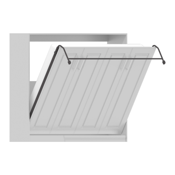
- Page 29 Chapter 5: Attaching the Bed Face Panel to the Bed Cabinet. For video instructions of this specific chapter, visit: breda.us/face FIG. 5C - LOOKING THROUGH LEFT SIDE FIG. 5D - LOOKING THROUGH LEFT SIDE 1. Referring to Fig. 5C, stand the Bed Face Panel in vertical position between the mechanism arms, lifting until the bolt in STEP 4 Hole #3 drops in the slotted portion of each mechanism arm.
-
Page 30: Chapter 6: Installing The Handles, Leg Support And Mattress
Chapter 6: Installing the handles, leg support and mattress. Chapter 6: Installing the handles, leg support and mattress. REQUIRED TOOLS REQUIRED HARDWARE • Cordless Drill w/ bit holder • Hardware Package #4 • #2 Phillips bit • Hardware Package #5 (Optional) •... - Page 31 Chapter 6: Installing the handles, leg support and mattress. FIG. 6B - LEG AND CONNECTOR ROD, LEFT SIDE STEP 3 Install the leg connector rod between the legs and secure with 1/4”-20 x 1 1/4” Hex head bolts and star washers from Hardware Package #4 and securely tighten...
-
Page 32: Chapter 7: Final Adjustment For The Bed Cabinet And Springs
Bed Cabinet Top Nailer from the wall. Prior to doing this, measure how far and in what direction the bed cabinet needs to shift in order to achieve alignment. If you have any question, contact us (phone: 1-855-466-4781, email: service@bredabeds.com or live chat: https://bredabeds.com) before doing anything. - Page 33 Chapter 7: Final adjustment for the Bed Cabinet and springs. To determine the proper tension, the mattress needs to be in place. The face assembly should raise and lower with about STEP 3 10 pounds of pressure and bed legs should rest on the floor without lifting when bed is open.
-
Page 34: Chapter 8: How To Disassemble The Bed For Moving
Chapter 8: How to disassemble the bed for moving. Chapter 8: How to disassemble the bed for moving. REQUIRED TOOLS ESTIMATED TIME • Cordless Drill with #2 Phillips 30 Minutes • 1/2 Wrench or Adjustable Pliers Note: This is an average time only, yours may vary.
Need help?
Do you have a question about the HORIZONTAL MURPHY BED and is the answer not in the manual?
Questions and answers