Table of Contents
Advertisement
Quick Links
Advertisement
Table of Contents

Related Manuals for Snap-On PRO-LINK EDGE


Summary of Contents for Snap-On PRO-LINK EDGE
- Page 1 ® PRO-LINK EDGE EEHD959001 HARDWARE AND SOFTWARE USER’S MANUAL...
- Page 2 IDSC Holdings LLC. PRO-LINK is a registered trademark of IDSC Holdings LLC. Snap-on is a trademark of Snap-on Incorporated. ©2019 Snap-on Incorporated. All other marks are trademarks or registered trademarks of the respective holders.
-
Page 3: Table Of Contents
Chapter 1: Using this Manual ..........1 Manual Overview ................2 Conventions ...................3 Chapter 2: Hardware and User Interface Overview ....5 Component Checklist ..............6 Product Specifications ..............7 Hardware Overview ...............9 Front View .................... 9 Top View .................... 10 Back View ................... 11 Back View Showing Battery Pack ............ - Page 4 Chapter 3: Getting Started ........... 29 Supplying Power to the PRO-LINK® Edge .........30 Connecting to a Vehicle ..............31 Scanning a Vehicle ..............33 Heavy Duty Scan ................34 Light and Medium Truck Scan ............38 Introduction to Tab Functions ............41 The Faults Tab ...................
- Page 5 Features Available from the Drop-Down Menu ......94 Viewing Vehicle Specifications ............94 Creating a Report ................96 Changing Units of Measure .............. 104 Play Recording ................. 105 Logout Repair-Connect ..............107 Support ..................... 109 Ending Your Diagnostics Session ............ 111 About PRO-LINK®...
- Page 6 Chapter 7: Using the Applications Menu ....... 151 Introduction to the Applications Menu ........152 Available Upgrades ................153 Available Apps .................. 154 Coming Soon ..................154 Installed Apps ................... 155 Register Apps ................... 157 Chapter 8: Using the Support Menu ........159 Introduction to the Support Menu ..........160 System .....................
- Page 7 Chapter 10: ® Using PRO-LINK Repair-Connect ....... 188 PRO-LINK® Repair-Connect Overview ........189 Logging In ..................190 The Description Tab ..............194 The Testing Tab ................196 The Specs Tab ................198 The Wiring/Locator Tab .............201 The Remove & Install Tab ............205 Appendix A: Warranty &...
-
Page 8: Using This Manual
Using this Manual Manual Overview, page 2 Conventions, page 3 his chapter provides an overview of this manual’s organization and the conventions used throughout. NOTE: Screen shots used throughout this manual are for illustrative purposes only. All data shown is fictitious in nature. -
Page 9: Manual Overview
Chapter • Using this Manual Manual Overview This manual provides basic and detailed information to support you in using the ® PRO-LINK Edge. This manual is composed of the following sections: • Table of Contents—helps you to find the information you are looking for quickly and easily. -
Page 10: Conventions
- Conventions Conventions This section provides descriptions of the conventions used throughout this guide. Special Messages Note NOTE provides an explanation, comment, or tip related to the subject matter that is being discussed. Example: NOTE: Refer to the page number provided for each described component for fur- ther details. - Page 11 Chapter • Using this Manual Warning WARNING indicates a potentially hazardous situation which, if not avoided, could result in death or serious injury to the operator or bystanders. Example: WARNING: ä Use appropriate hand protection when handling hot engine components. Troubleshooting Information intended to help you to address or anticipate potential issues are pre- sented in the following manner:...
- Page 12 Hardware and User Interface Overview Component Checklist, page 6 Product Specifications, page 7 Hardware Overview, page 9 User Interface Overview, page 15 The Main Menu, page 15 Vehicle Scan, page 20 The Vehicle History Menu, page 23 ...
-
Page 13: Hardware And User Interface Overview
NOTE: For access to Special Tests and Calibrations (or, if you run out of free trials), please contact your Snap-on franchisee to purchase a Product Key for any of the software application suites. Once you have the Product Key, touch Applications on the PRO-LINK® Edge Main Menu. Then touch Installed Apps. -
Page 14: Product Specifications
- Product Specifications Product Specifications ® The PRO-LINK Edge is configured with the following specifications: Feature Data Physical Dimensions, 11 x 7.64 x 2.1 inches (cm) (27.94 x 19.405 x 5.334) Weight (with standard battery), lb (KG) 3.10 (1.40) Operating Temperature, Fahrenheit 14 to 122 °F (-10 to 50 °C) (Celsius) - Page 15 Chapter • Hardware and User Interface Overview Feature Data Certifications UL, cUL Wireless Module Certifications FCC/IC, CE. MIC Battery Certifications UL 2054, IEC 62133, 2nd Edition, UN 38.3 Warranty 1 Year Repair Phone Number (800) 311-5452, Option 3 ® PRO-LINK Edge Hardware and Software User’s Manual...
-
Page 16: Hardware Overview
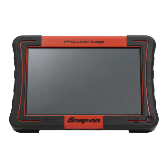
- Hardware Overview Hardware Overview ® This section introduces the PRO-LINK Edge hardware, its ports, and connections. Front View Figure 2.1 ® Front View of the PRO-LINK Edge ® PRO-LINK Edge Hardware and Software User’s Manual... -
Page 17: Top View
Chapter • Hardware and User Interface Overview Top View Figure 2.2 ® Top View of the PRO-LINK Edge ® 10 PRO-LINK Edge Hardware and Software User’s Manual... -
Page 18: Back View
- Hardware Overview Back View Figure 2.3 ® Back View of the PRO-LINK Edge WARNING: ä ® The stand on the back of the PRO-LINK Edge makes it possible to hang the device from the steering wheel. We recommend strongly that you refrain from doing this while the vehicle is in motion. -
Page 19: Back View Showing Battery Pack
Chapter • Hardware and User Interface Overview Back View Showing Battery Pack Figure 2.4 Back View Showing the Battery Compartment Open To remove the battery pack, you must first remove the screw that holds the battery pack in place. ® 12 PRO-LINK Edge Hardware and Software User’s Manual... -
Page 20: Monitoring Battery Power
- Hardware Overview Monitoring Battery Power ® The PRO-LINK Edge obtains power from any of the following source: • Its own internal battery pack • The vehicle (when in a connected state) • AC/DC power adapter (when plugged into a power source) Battery Icon Figure 2.5... -
Page 21: Disposing Of The Battery Pack
Chapter • Hardware and User Interface Overview Disposing of the Battery Pack Always dispose of the battery pack according to local regulations, which vary for different countries and regions. The battery pack, while non-hazardous waste, does contain recyclable materials. If shipping is required, ship the battery pack to a recycling facility in accordance with local, national, and international regulations. -
Page 22: User Interface Overview
- User Interface Overview User Interface Overview This section provides an overview of the following menus and features: • The Main Menu (pg. 15) • Vehicle Scan (pg. 20) • The Vehicle History Menu (pg. 23) • The Settings Menu (pg. 24) •... - Page 23 Chapter • Hardware and User Interface Overview The following table introduces the items on the Main Menu: Menu Item What It Does Vehicle Scan Presents two choices: • HD Scan--Automatically scans the vehicle and presents a list of ECMs detected during scanning (J1708 and J1939).
- Page 24 - User Interface Overview Menu Item What It Does Settings Displays the following choices: • Wireless--network tools, including: --Connect to a wireless network --Add a wireless network --Change wireless settings --Check Wireless Status --Configure Proxy • Printers--tools to manage printers, including: --Add Printer --Print Test Page...
- Page 25 Chapter • Hardware and User Interface Overview Menu Item What It Does Support Displays the following choices: • System--system information, including: --Get Support --Device information --Network information --Remote Access On/Off --A list of Installed Applications • Account--account information, including: --Create Account (if the device is not cur- rently registered) --Account Login --Reset Password...
- Page 26 • Play Recording--play recording previously stored on the device • Logout Repair-Connect--logout of Repair- Connect (Repair-Connect requires a special subscription; see your Snap-on Franchisee) • Support--displays the Support Menu, dis- cussed earlier in this table • About--displays the following information:...
-
Page 27: Vehicle Scan
Chapter • Hardware and User Interface Overview Vehicle Scan When you select Vehicle Scan from the Main Menu, the following screen is displayed: Figure 2.7 Vehicle Scan Menu The following scanning options are available: • HD Scan (Auto)—Scans the vehicle, presents a list of ECMs detected during scanning (J1708 and J1939), and enables you to select up to six (6) modules from the list. -
Page 28: The Diagnostics Menu
- User Interface Overview The Diagnostics Menu When the scanning process is complete, the Diagnostics Menu is displayed: Figure 2.8 Diagnostics Menu The Diagnostics Menu is composed of a number of tabs along the left side of the screen. You use these tabs to access different types of diagnostic information and features. -
Page 29: The Drop-Down Menu: Connected Status
• Support—Displays the Support screen • End Session—Ends the session, disconnects from the vehicle, and re- turns you to the Main Menu (Figure 2.6). • About—Displays the PRO-LINK Edge information box; also available when not connected to a vehicle. ®... -
Page 30: The Vehicle History Menu
- User Interface Overview The Vehicle History Menu When you select Vehicle History from the Main Menu, the Manage Reports screen is displayed. NOTE: For detailed information on the Vehicle History Menu, see Chapter 5: Using the Vehicle History Menu, later in this guide. Figure 2.10 Manage Reports Screen You use this screen to manage reports created and saved on the device, for... -
Page 31: The Settings Menu
Chapter • Hardware and User Interface Overview The Settings Menu You access the Settings Menu from the Main Menu (Figure 2.6). NOTE: For detailed information on the Settings Menu, refer to Chapter 5: Using the Settings Menu, later in this manual. Menu selections are displayed on the left side of the screen: •... -
Page 32: The Applications Menu
- User Interface Overview The Applications Menu You access the Applications Menu from the Main Menu (Figure 2.6). Menu selec- tions are displayed on the left side of the screen: • Available Upgrades • Available Apps • Coming Soon • Installed Apps Figure 2.12 Applications Menu Use the Exit button at the bottom of the screen to return to the Main Menu. -
Page 33: The Support Menu
Chapter • Hardware and User Interface Overview The Support Menu You access the Support Menu from the Main Menu (Figure 2.6). NOTE: For detailed information on the Support Menu, refer to Chapter 8: Using the Support Menu, later in this manual. Menu selections are displayed on the left side of the screen: •... -
Page 34: Navigational Features
- User Interface Overview Navigational Features ® The PRO-LINK Edge is designed for ease of use in on-road conditions, in the service bay, or in test situations. Depending on the circumstances of use, you can make selections, and move from one screen to the next, by touching the screen with your finger. - Page 35 Chapter • Hardware and User Interface Overview Icon What the Icon Does SD Card Present • Indicates that an SD card is present in the SD slot • Located on the toolbar when a micro SD card is inserted USB Device Present •...
- Page 36 Getting Started Supplying Power to the PRO-LINK® Edge, page 30 Connecting to a Vehicle, page 31 Scanning a Vehicle, page 33 Heavy Duty Scan, page 34 Light and Medium Truck Scan, page 38 Introduction to Tab Functions, page 41 ...
-
Page 37: Chapter 3: Getting Started
Chapter • Getting Started ® Supplying Power to the PRO-LINK Edge ® There are three ways to supply power to the PRO-LINK Edge. You can use the: • On-board battery—A 10.8 volt, 3.2 AH Li-ion battery is included with your device. ®... -
Page 38: Connecting To A Vehicle
- Connecting to a Vehicle Connecting to a Vehicle ® Prior to using the PRO-LINK Edge for diagnostics, you must connect to a vehicle using the power data cable and the appropriate adapter. The vehicle should be in a key-on, engine-off state. To connect to a vehicle: Make sure the vehicle ignition is in the ON position, however, the engine does not have to be running. - Page 39 Chapter • Getting Started ® When you power up the PRO-LINK Edge, the following screen is displayed. Figure 3.1 Main Menu To begin scanning, move on to Scanning a Vehicle, next in this manual. ® 32 PRO-LINK Edge Hardware and Software User’s Manual...
-
Page 40: Scanning A Vehicle
- Scanning a Vehicle Scanning a Vehicle The following scanning options are available: • HD Scan (Auto)—Scans the vehicle, presents a list of ECMs detected during scanning, and enables you to select up to six (6) modules from the list. •... -
Page 41: Heavy Duty Scan
Chapter • Getting Started Heavy Duty Scan If you selected HD Scan on the Vehicle Scan Menu (Figure 3.2), the device scans the vehicle to identify available modules. Figure 3.3 Scanning Vehicle Screen Wait for a moment or two for the next screen to display. ®... - Page 42 - Scanning a Vehicle The Module Selection screen is displayed. Figure 3.4 Module Selection Screen NOTE: The device displays the available modules (e.g., Engine) followed by the name of the software application that will be used to communicate with the module (e.g., Paccar - Ch1).
- Page 43 Chapter • Getting Started Your selections are highlighted. Figure 3.5 Module Selection Screen with Item Highlighted Touch OK. ® The PRO-LINK Edge loads each of the selected modules. ® 36 PRO-LINK Edge Hardware and Software User’s Manual...
- Page 44 - Scanning a Vehicle The Diagnostics Menu is displayed. Figure 3.6 Diagnostics Menu ® PRO-LINK Edge Hardware and Software User’s Manual...
-
Page 45: Light And Medium Truck Scan
Chapter • Getting Started Light and Medium Truck Scan When you select LMT from the Vehicle Scan Menu (Figure 3.2), the follow- ing screen is displayed. Figure 3.7 OBD II/Light Medium Truck Screen Select the appropriate application for the truck you are connected to from the list on the right. - Page 46 - Scanning a Vehicle The screen is refreshed and a list of model years is displayed on the right side of the display. Figure 3.8 Select the Model Year Select the appropriate model year from the list Figure 3.9 Select the VIN Select the VIN from the list.
- Page 47 Chapter • Getting Started Figure 3.10 All Three Selections Made Review your selections, and touch OK. Figure 3.11 Module Selection Screen Select up to six modules to load, and touch OK. The Diagnostics Menu is displayed (Figure 3.12). ® 40 PRO-LINK Edge Hardware and Software User’s Manual...
-
Page 48: Introduction To Tab Functions
- Introduction to Tab Functions Introduction to Tab Functions ® Once the PRO-LINK Edge has scanned the vehicle for faults, the Diagnostics Menu is displayed (Figure 3.12). A number of menu-selection tabs are displayed on the left side of the screen. •... -
Page 49: The Parameters Tab
Chapter • Getting Started The Parameters Tab ® The PRO-LINK Edge creates a Parameters tab for each module loaded (e.g., Engine and Engine Retarder). Depending on the number of modules loaded, you may, or may not, have multiple parameters tabs displayed. Figure 3.13 Category Selection Screen The first time the Parameters tab is selected during your session the you are... - Page 50 - Introduction to Tab Functions The Parameters screen is displayed. Figure 3.14 Parameters Screen Use your finger to drag and scroll through all the items in the list. NOTE: Touch a parameter in the list to add it to your Quick List. For detailed infor- mation on creating a Quick List, refer to “Creating and Viewing a Quick List”...
-
Page 51: The Calibrations Tab
Chapter • Getting Started The Calibrations Tab The Calibrations tab lists the calibrations available for each module and displays the screens you need to calibrate those parameters. If a module does not contain any calibrations, a message is displayed. NOTE: For some parameters a password is required. - Page 52 - Introduction to Tab Functions A list of available categories is displayed. Figure 3.16 List of Available Categories NOTE: You can use your finger to drag and scroll through all the items in the list. Touch the screen to make your selection (e.g., Cruise Control), and view calibrations for that category.
- Page 53 Chapter • Getting Started The Cruise Control screen is displayed. Figure 3.17 Cruise Control Screen Touch the screen to select a calibration (e.g., Cruise Control Vehicle Speed High Limit). ® 46 PRO-LINK Edge Hardware and Software User’s Manual...
- Page 54 - Introduction to Tab Functions The calibration screen is displayed. Figure 3.18 Sample Calibrations Screen NOTE: Note the Minimum and Maximum values displayed for your reference. After you have entered the New Value, touch Update. ® PRO-LINK Edge Hardware and Software User’s Manual...
- Page 55 Chapter • Getting Started The Cruise Control Screen is updated with the value you entered. Figure 3.19 Cruise Control Screen Updated with New Value Touch the Program button to finalize the calibration. NOTE: You may receive a series of messages directing you to cycle the ignition. Follow the prompts.
-
Page 56: The Tests Tab
- Introduction to Tab Functions The Tests Tab The Tests tab is used to perform special tests. Some of the tests you can run include the following: • Histograms • Injector actuation pressure tests • Injector solenoid tests A typical test enables you to perform a function or test to aid in the diagnostics of a vehicle or system. - Page 57 Chapter • Getting Started Once you select the module from the list on the left, a list of available tests for that module is displayed. Figure 3.21 Available Tests Screen Select a test from the list to display the screen for that test. Then, follow the on-screen prompts to run the test.
-
Page 58: Viewing Vehicle Specifications
- Viewing Vehicle Specifications Viewing Vehicle Specifications The Vehicle Specs feature is accessed through the drop-down menu in the upper- left corner of the display when you are connected to a vehicle. Figure 3.22 Drop-down Menu Showing the View Vehicle Specs Menu Item When you touch the View Specs button, the following information is dis- played for the vehicle to which you are connected: •... - Page 59 Chapter • Getting Started The Vehicle Specifications screen is displayed. Figure 3.23 Vehicle Specifications Screen Touch the Print button to save the information to a file, or to print directly to a printer if you are connected to a printer. NOTE: For information on setting up a printer, refer to “Managing Printers”...
-
Page 60: Monitoring Battery Power
- Monitoring Battery Power Monitoring Battery Power ® The PRO-LINK Edge obtains power from any of the following sources: • Its own internal battery pack • The vehicle (when connected to a vehicle) • AC/DC power adapter (when plugged into a power source) Figure 3.24 Main Menu Showing the Battery Icon The Battery icon has two states:... -
Page 61: Using The Diagnostics Menu
Using the Diagnostics Menu The Diagnostics Menu, page 58 Faults, page 59 Clearing Inactive Faults, page 62 Parameters, page 63 Managing Quick Lists, page 65 Graphing Data, page 74 Calibrations, page 76 ... -
Page 62: The Diagnostics Menu
Chapter • Using the Diagnostics Menu The Diagnostics Menu ® Once the PRO-LINK Edge has successfully scanned the vehicle for faults, the Diagnostics Menu is displayed. NOTE: For detailed information on connecting to a vehicle and the scanning pro- cess, refer to “Connecting to a Vehicle” and “Scanning a Vehicle” in Chapter 3: Getting Started, earlier in this manual. -
Page 63: Faults
- The Diagnostics Menu Faults The Faults screen is the default display on the Diagnostics Menu. Other selections are available on the left side of the display (e.g., Engine, Calibrations, Tests). From the faults screen display you can: • View active and inactive faults (pg. 59) •... - Page 64 Chapter • Using the Diagnostics Menu Each fault listed contains the following information for that fault: Line Number Contents The name of the module where the fault was found (e.g., Engine 1 - Paccar) Either the name of the parameter experienc- ing the fault, or a combination of the name and a description of the fault (e.g., Inlet air pressure in inlet manifold - Voltage too low or...
- Page 65 - The Diagnostics Menu The More Info screen is displayed with the Description pane activated. Figure 4.3 More Info Screen Touch the Freeze Frame button at the top of the display to view freeze frame information (if available). Touch the Description button to go back to the description pane. NOTE: If you have purchased a subscription to Repair-Connect, touch the PRO- ®...
-
Page 66: Clearing Inactive Faults
Chapter • Using the Diagnostics Menu Clearing Inactive Faults Inactive faults can be cleared by touching the Clear All Faults button at the bottom of the screen. Faults may not be cleared individually. NOTE: When you clear all faults, both ACTIVE and INACTIVE faults are cleared. ®... -
Page 67: Parameters
- The Diagnostics Menu Parameters The Parameters screen is accessed by touching one of the Parameters tabs (e.g., Engine) on the left-side of the Diagnostics Menu. NOTE: ® The PRO-LINK Edge creates a Parameters tab for each module (e.g., Engine - Paccar - Ch1 and Engine Retarder- HDS J1939 Ch1) loaded during the scanning process. -
Page 68: Viewing Parameters
Chapter • Using the Diagnostics Menu Viewing Parameters To view parameters: From the Diagnostics Menu (Figure 4.1), select the Parameters tab (e.g., Engine) Figure 4.6 Select a Category Screen NOTE: Touch the screen, and drag your finger up to scroll down the list on the left. Touch the name of the category for which you want to view live data (e.g., Pressures). -
Page 69: Managing Quick Lists
- The Diagnostics Menu A list of parameters for the selected category is displayed. Figure 4.7 List of Parameters All parameters available for the category you selected (e.g., Pressures) are displayed in the list to the right of the categories. Values, if available, are also displayed. - Page 70 Chapter • Using the Diagnostics Menu A sample quick list. Figure 4.8 Sample Quick List NOTE: The Quick List is limited to ten (10) parameters ® 66 PRO-LINK Edge Hardware and Software User’s Manual...
- Page 71 - The Diagnostics Menu Creating and Viewing a Quick List A Quick List is created by checking individual parameters from one or more cate- gories in the list of parameters. If no parameters are yet in the Quick List, a screen explaining how to add parameters to the Quick List is displayed.
- Page 72 Chapter • Using the Diagnostics Menu A list of parameters for the selected category is displayed. Figure 4.10 Parameter List for Pressures NOTE: Touch the screen, and drag your finger up to move down the list. Touch the screen to select a parameter (e.g., DEF Pressure). ®...
- Page 73 - The Diagnostics Menu Your selection is highlighted. Figure 4.11 Selection Highlighted and Added to the Quick List Note that there is now one (1) item in the Quick List box (located at the top- left portion of the screen). Continue adding parameters to the list.
- Page 74 Chapter • Using the Diagnostics Menu The Quick List is displayed. Figure 4.12 Sample Quick List NOTE: For information on using the Graph button to graph parameter data, see Graphing Data on page 74 of this chapter. NOTE: The Record Mode feature is discussed in Chapter 9: Using Record and Playback, later in this manual.
- Page 75 - The Diagnostics Menu Removing Parameters from the Quick List You can remove parameters form the Quick List at any time. To remove a parameter from the Quick List: Touch Quick List at the top of the list of categories to display the current Quick List.
- Page 76 Chapter • Using the Diagnostics Menu The selected parameter is highlighted. Figure 4.14 Removing Parameters from the Quick List Touch the Remove Selected Items button. ® 72 PRO-LINK Edge Hardware and Software User’s Manual...
- Page 77 - The Diagnostics Menu The Quick List is updated. Figure 4.15 Updated Quick List To remove all parameters form the Quick List, touch the Clear Quick List button. The Select a Category screen is displayed again (Figure 4.9). ® PRO-LINK Edge Hardware and Software User’s Manual...
-
Page 78: Graphing Data
Chapter • Using the Diagnostics Menu Graphing Data You can view a visual representation (i.e., a graph) of the parameters in the Quick List by using the Graph button at the bottom of the screen (Figure 4.15). Only scalable parameters (i.e., parameters that have values that can vary over time) will be displayed, for example, temperatures. - Page 79 - The Diagnostics Menu The Quick List is displayed. Figure 4.17 Quick List Touch the Graph button. Figure 4.18 Sample Graph Touch the Back Arrow to return to the Quick List (Figure 4.17). ® PRO-LINK Edge Hardware and Software User’s Manual...
-
Page 80: Calibrations
Chapter • Using the Diagnostics Menu Calibrations From the Calibrations menu, you can: • Select a calibration category and view the associated datapoints (pg. 77) • Calibrate a datapoint (pg. 80) Figure 4.19 Sample Calibrations Screen NOTE: Calibrations are not available for all software applications. For example, Heavy Duty Standard (HDS) J1939, among others, does not support cali- brations. -
Page 81: Select A Calibration Category
- The Diagnostics Menu Select a Calibration Category A calibration category is a collection of related calibrations. The first time you ® select the Calibrations tab during a session, the PRO-LINK Edge prompts you to select a module, and then displays the available calibration categories for that module. - Page 82 Chapter • Using the Diagnostics Menu A list of available categories is displayed. Figure 4.21 List of Available Categories Use your finger to scroll down the list. Touch the screen to select the category you want (e.g., Engine Idle Shutdown Control). ®...
- Page 83 - The Diagnostics Menu ® The PRO-LINK Edge displays a list of the datapoints you can calibrate for the selected category (datapoints on the left and values on the right). Figure 4.22 List of Datapoints within a Category Move on to Calibrating a Datapoint, next. ®...
-
Page 84: Calibrating A Datapoint
Chapter • Using the Diagnostics Menu Calibrating a Datapoint ® When you select a datapoint to calibrate the PRO-LINK Edge immediately starts the calibration process for that datapoint. NOTE: Each calibration screen is unique to the type of module and the type of cal- ®... - Page 85 - The Diagnostics Menu The calibration screen for the datapoint you selected is displayed. Figure 4.24 Calibration Screen Touch within the New Value data entry field. NOTE: When a calibration is running, the CALS tab is locked. Touch the Quit button to exit the calibration.
- Page 86 Chapter • Using the Diagnostics Menu The keyboard is displayed. Figure 4.25 Keyboard Use the keyboard to enter the new value (e.g., 70). Touch the Update button at the bottom of the screen. ® 82 PRO-LINK Edge Hardware and Software User’s Manual...
- Page 87 - The Diagnostics Menu The list of datapoints is displayed, showing the new value. Figure 4.26 List of Datapoints for the Cruise Control Category To complete the calibration, and accept the new value, touch the Program button. If you choose not to program the calibration at this time, you can continue to make additional calibrations, and then program all of your calibrations at the same time.
- Page 88 Chapter • Using the Diagnostics Menu Wait while the calibration is verified. The list of datapoints is displayed again. Figure 4.27 List of Datapoints for the Cruise Control Category Continue to calibrate other datapoints, or select a different category from the list on the left.
-
Page 89: Tests
- The Diagnostics Menu Tests ® The PRO-LINK Edge provides a wide range of special tests. However, the avail- ability of tests is dependent on both the vehicle to which the device is connected and the module loaded (e.g., engine, transmission, etc.). The first time you select the Tests tab during the current session, you are prompted to select a module. - Page 90 Chapter • Using the Diagnostics Menu To run a test: Start at the Diagnostics Menu. Figure 4.28 Diagnostics Menu Select Tests from the list on the left. Figure 4.29 To View Special Tests, Select a Module Select a module from the list on the left (e.g., Engine - Paccar CH1). ®...
- Page 91 - The Diagnostics Menu The Caution screen is displayed. Figure 4.30 Caution Screen Carefully read the on-screen instructions and follow them. Touch OK. ® PRO-LINK Edge Hardware and Software User’s Manual...
- Page 92 Chapter • Using the Diagnostics Menu A list of tests is displayed for the selected module. Figure 4.31 List of Available Tests Touch the screen to select a test from the list (e.g., Injector Code Programming). ® 88 PRO-LINK Edge Hardware and Software User’s Manual...
- Page 93 - The Diagnostics Menu A Warning screen is displayed. Figure 4.32 Warning Screen Touch OK after reading the information provided. Figure 4.33 Warning Screen Touch the Info Text icon in the upper-right corner. ® PRO-LINK Edge Hardware and Software User’s Manual...
- Page 94 Chapter • Using the Diagnostics Menu The Info Text screen for Injector Code Programming is displayed. Figure 4.34 Info Text Screen for Injector Code Programming Touch the screen, and drag your finger up to scroll down through the information. Figure 4.35 Info Text for Injector Code Programming 2 ®...
- Page 95 - The Diagnostics Menu (optional) Touch Print to save the information to a file for later reference (or to print the file to a printer if you have one installed). When you have finished reading the information, touch Back to return to the test screen.
- Page 96 Chapter • Using the Diagnostics Menu The Swap Injector Codes screen is displayed. Figure 4.37 Swap Injector Screen Touch within the first data entry box. Use the keyboard to enter an injector number. Repeat for the second data entry box. Touch OK.
- Page 97 - The Diagnostics Menu The list of available tests is displayed again. Figure 4.38 List of AVailable Tests ® PRO-LINK Edge Hardware and Software User’s Manual...
-
Page 98: Features Available From The Drop-Down Menu
Chapter • Using the Diagnostics Menu Features Available from the Drop-Down Menu Several features are available from the drop-down menu at the top of the Diagnos- tics Menu. • View Vehicle Specs (pg. 94) • Create Report (pg. 96) • Units (pg. 104) •... - Page 99 - Features Available from the Drop-Down Menu The Vehicle Specifications screen is displayed. Figure 4.40 Vehicle Specifications (optional) Once you have finished viewing the information, touch the Print button to send the information to a printer (or to save it to a file). Touch the Back Arrow at the bottom of the screen to return to the Diagnostics Menu (Figure 4.39).
-
Page 100: Creating A Report
Chapter • Using the Diagnostics Menu Creating a Report To create a report: Touch the drop-down menu in the upper-left corner of the screen. Figure 4.41 Diagnostics Menu Select Create Report. ® 96 PRO-LINK Edge Hardware and Software User’s Manual... - Page 101 - Features Available from the Drop-Down Menu The Information Selection screen is displayed. Figure 4.42 Information Selection Screen Touch the screen to select the type of information you want to display on your report (e.g., Vehicle Info, Faults, System Details, etc.). ®...
- Page 102 Chapter • Using the Diagnostics Menu Check marks are displayed next to your selections. Figure 4.43 Check Marks Indicate Selections Made (optional) Touch the Change button to select a different module or parameter category for the data you want to include. For example, you want to include on your report specific parameters (e.g., Engine - Paccar - Pressures).
- Page 103 - Features Available from the Drop-Down Menu The following screen is displayed. Figure 4.44 Change Selection Screen Touch the Category drop-down to display a list of available parameter cate- gories for the selected Controller. Select a different parameter category from the list (e.g., Pressures). Touch the OK button at the bottom of the screen.
- Page 104 Chapter • Using the Diagnostics Menu The Information Selection screen is displayed again reflecting the change. Figure 4.45 Information Selection Screen Touch the screen to select the Parameters for the category you selected in Step 6 of this procedure. Figure 4.46 Information Selection Screen Updated Touch the Print button.
- Page 105 - Features Available from the Drop-Down Menu The Select Printer screen is displayed. Figure 4.47 Select Printer Screen Touch Next to save the report to a file in portable document format (PDF) for later viewing or printing. NOTE: For information on managing your saved reports (including printing reports), see Chapter 5: Using the Vehicle History Menu, later in this manual.
- Page 106 Chapter • Using the Diagnostics Menu The following screen is displayed. Figure 4.48 Select Destination Screen Touch the screen to indicate where you want the report saved (i.e., to the ® PRO-LINK Edge, an SD card, or a USB drive). Touch Select.
- Page 107 - Features Available from the Drop-Down Menu The Save As screen is displayed. Figure 4.50 Save As Screen Touch within the Name field if you wish to give the report a specific name (i.e., other than the numeric name automatically assigned by the device). Use the keyboard to enter a new name for your report, for example, ...
-
Page 108: Changing Units Of Measure
Chapter • Using the Diagnostics Menu Changing Units of Measure To change units of measure: Touch the drop-down menu. Figure 4.51 Diagnostics Menu Select Units. Figure 4.52 Diagnostics Menu ® 104 PRO-LINK Edge Hardware and Software User’s Manual... -
Page 109: Play Recording
- Features Available from the Drop-Down Menu Two options are available: • English (lbs., mph, °F) • Metric (kg, kph, ° C) ® Select the unit of measure you want PRO-LINK Edge to use. The menu closes, and the underlying Diagnostics Menu is displayed. Play Recording The Play Recording menu item is not available if you have not previously created a recording. - Page 110 Chapter • Using the Diagnostics Menu The playback screen is displayed. Figure 4.54 Playback Screen Touch Play to begin the recording. Touch Exit to return to the Diagnostics Menu (Figure 4.53). ® 106 PRO-LINK Edge Hardware and Software User’s Manual...
-
Page 111: Logout Repair-Connect
- Features Available from the Drop-Down Menu Logout Repair-Connect ® Once you have logged in to Repair-Connect, PRO-LINK Edge remembers your login credentials so you don’t have to enter them again. Then, you are automati- cally logged when you access detailed information for a fault during your active diagnostic session.This is why the Logout Repair-Connect feature is only avail- able once you have logged into Repair-Connect for the current session. - Page 112 Chapter • Using the Diagnostics Menu You are returned to your diagnostic session, but are no longer logged in to Repair-Connect. Figure 4.56 Fault More Info Screen while Logged Out of Repair-Connect NOTE: ® To log back in, touch the PRO-LINK Repair-Connect button at the top of the display (see Figure 4.56).
-
Page 113: Support
- Features Available from the Drop-Down Menu Support You can access the Support Menu while connected to a vehicle by using the drop- down menu in the upper-left corner of the display. In addition, you can access the Support Menu by touching the Support icon located in the toolbar at the top of the display. - Page 114 Chapter • Using the Diagnostics Menu The Support Menu is displayed. Figure 4.58 Support Menu Touch the Back Arrow to return to the Diagnostics Menu (Figure 4.57). ® 110 PRO-LINK Edge Hardware and Software User’s Manual...
-
Page 115: Ending Your Diagnostics Session
- Features Available from the Drop-Down Menu Ending Your Diagnostics Session To end your diagnostics session and disconnect from the vehicle, you use the drop-down menu in the upper-left corner of the screen. To end your diagnostics session: Touch the drop-down menu. Figure 4.59 Diagnostics Menu Select End Session. - Page 116 Chapter • Using the Diagnostics Menu The Vehicle Scan Menu is displayed. Figure 4.60 Vehicle Scan Menu Touch the Back Arrow. ® 112 PRO-LINK Edge Hardware and Software User’s Manual...
- Page 117 - Features Available from the Drop-Down Menu The Main Menu is displayed. Figure 4.61 Main Menu From this menu you can: —Scan another vehicle, and start another diagnostic session (see “Scanning a Vehicle” in Chapter 3: Getting Started, of this manual). —View Vehicle History —Navigate to the Settings menu (see Chapter 6) —Navigate to the Applications menu (see Chapter 7)
-
Page 118: About Pro-Link Edge
Chapter • Using the Diagnostics Menu About PRO-LINK Edge ® To view information about PRO-LINK ® Edge: Touch the drop-down menu at the top of the screen. Figure 4.62 Diagnostics Menu: Drop-down Menu Selected Select About. ® 114 PRO-LINK Edge Hardware and Software User’s Manual... - Page 119 - Features Available from the Drop-Down Menu The About information box is displayed. Figure 4.63 About Information Box Touch the Close Button in the upper-right corner of the box. The information box closes, and the underlying Diagnostics Menu is displayed. ®...
- Page 120 Using the Vehicle History Menu Managing Saved Reports, page 118 Deleting a Report, page 120 Moving a Report, page 121 Printing a Report, page 122 Previewing a Report, page 125 his chapter provides detailed instructions for using the Vehicle History Menu to manage reports.
-
Page 121: Using The Vehicle History Menu
Chapter • Using the Vehicle History Menu Managing Saved Reports You access the Vehicle History, which displays the Manage Reports screen, from the Main Menu. Figure 5.1 Main Menu NOTE: For an overview of the options available on the Main Menu, see “The Main Menu,”... - Page 122 - Managing Saved Reports To manage your saved reports: Select Vehicle History from the Main Menu (Figure 5.1). The Manage Reports screen is displayed. Figure 5.2 Manage Reports Screen You can change the order in which your reports are displayed in the list by touching the Sort by drop-down menu and selection an option.
-
Page 123: Deleting A Report
Chapter • Using the Vehicle History Menu Deleting a Report To delete a report: Touch the screen to select the report you want to delete. Your selection is highlighted. Figure 5.3 Selection Highlighted Touch the Delete button. An Are you sure? message is displayed. Touch Yes. -
Page 124: Moving A Report
- Managing Saved Reports Moving a Report ® You can move a report saved to your PRO-LINK Edge to a storage device (e.g., a USB memory stick or a secure digital (SD) memory card). To move a report to a storage device: Touch the screen to select the report or reports you want to move. -
Page 125: Printing A Report
Chapter • Using the Vehicle History Menu The Select Destination screen is displayed. Figure 5.5 Select Destination Screen You can choose between SD Card and USB Drive, depending on the type of storage device you have. Touch the Select button to accept the default (i.e., USB Drive). ®... - Page 126 - Managing Saved Reports Your selection is highlighted. Figure 5.6 Selection Highlighted Touch the Print button. ® PRO-LINK Edge Hardware and Software User’s Manual 123...
- Page 127 Chapter • Using the Vehicle History Menu The Select Printer screen is displayed. Figure 5.7 Select Printer Screen Select a printer from the list of available printers. NOTE: You can also add a printer to the list of available printers by touching Add Printer.
-
Page 128: Previewing A Report
- Managing Saved Reports Previewing a Report You can preview a report to confirm that it’s the report you want. To preview a report: Touch the screen to select the report you want to preview. Your selection is highlighted. Figure 5.8 Selection Highlighted Touch Preview. - Page 129 Chapter • Using the Vehicle History Menu The preview is displayed. Figure 5.9 Report Preview You can move from page to page by using the directional arrows at the top of the display. When you have finished viewing the information, do one of the following: •...
-
Page 130: Using The Settings Menu
Using the Settings Menu The Settings Menu, page 128 Managing Wireless Networks, page 130 Connecting to a Network, page 130 Adding a Wireless Network, page 132 Changing Wireless Settings, page 134 Check Wireless Status, page 137 ... -
Page 131: The Settings Menu
Chapter • Using the Settings Menu The Settings Menu The procedures in this chapter assume the following: ® • The PRO-LINK Edge is not connected to a vehicle. • You are performing the procedures as a system administrator in a non- shop setting. - Page 132 - The Settings Menu The Settings Menu is displayed. Figure 6.2 Settings Menu You use the Settings Menu to perform the following administrative tasks: • Manage Wireless Networks (pg. 130) • Manage Printers (pg. 141) • Set the Date and Time (pg. 146) •...
-
Page 133: Managing Wireless Networks
Chapter • Using the Settings Menu Managing Wireless Networks The following options are available: • Wireless Networks - Connecting to a Network (pg. 130) • Add Wireless Network (pg. 132) • Change Wireless Settings (pg. 134) • Check Wireless Status (pg. 137) •... - Page 134 - The Settings Menu To connect to a wireless network: Touch the screen to highlight the network in the list you wish to connect to (e.g., SBSPublic). NOTE: If the network you want to connect to does not appear in the list, you can add it.
-
Page 135: Adding A Wireless Network
Chapter • Using the Settings Menu Adding a Wireless Network If the network you want to connect to does not appear in the list displayed on the Wireless Networks screen (see Figure 6.3), you can add it. NOTE: It is recommended that you employ the assistance of the designated IT person or network administrator at your location prior to adding a wireless network. - Page 136 - The Settings Menu —Password Index (if appropriate) —Password —Check the Show Password check box if you want to display the password, otherwise leave it empty. Tap Connect. The Wireless Networks screen is displayed (Figure 6.3). ® PRO-LINK Edge Hardware and Software User’s Manual 133...
-
Page 137: Changing Wireless Settings
Chapter • Using the Settings Menu Changing Wireless Settings You use the Configure Wireless Adapter screen if you want to change what type ® of IP address your PRO-LINK Edge will have: • Dynamic IP address (automatically selected and variable) •... - Page 138 - The Settings Menu Touch within the IP Address data entry field. Figure 6.7 Screen with Keyboard Use the keyboard to enter the information. Touch within the Subnet Mask data entry field, and enter the information. Touch within the Gateway data entry field, and enter the information. Touch within the DNS Server data entry field, and enter the information.
- Page 139 Chapter • Using the Settings Menu The Wireless Networks screen is displayed. Figure 6.8 Wireless Networks ® 136 PRO-LINK Edge Hardware and Software User’s Manual...
-
Page 140: Check Wireless Status
- The Settings Menu Check Wireless Status You use the Network Adapter Status screen to view information about your wireless network settings. The following information is displayed: • Address Type • IP Address • Subnet Mask • Default Gateway • DNS •... -
Page 141: Configure Proxy
Chapter • Using the Settings Menu Configure Proxy If your local network is configured using a proxy server, you will need to enter in- ® formation to tell PRO-LINK Edge how to communicate with it. NOTE: If your local network is not configured using a proxy server, you do not need to enter these settings. - Page 142 - The Settings Menu The keyboard is displayed. Figure 6.11 Keyboard Use the keyboard to enter the server name. Touch within the Port data entry field, and enter the information. Touch the Requires Authentication check box to activate it if your proxy server requires a password.
- Page 143 Chapter • Using the Settings Menu The Settings Menu is displayed. Figure 6.12 Settings Menu ® 140 PRO-LINK Edge Hardware and Software User’s Manual...
-
Page 144: Managing Printers
- The Settings Menu Managing Printers Figure 6.13 Manage Printers Screen You use the Manage Printers screen to do the following: • Add Printer and Print a Test Page (pg. 142) • Set as Default (pg. 145) Use this to set your default printer. It also enables you to set your print default to either print the information to a printer or to save it to a file (e.g.,a PDF). -
Page 145: Adding A Printer And Printing A Test Page
Chapter • Using the Settings Menu Adding a Printer and Printing a Test Page Prior to starting this procedure, you may need to gather the following information: • Network path for the printer you want to print to • Network security information, if required: —... - Page 146 - The Settings Menu The Add Printer screen is displayed. Figure 6.15 Add Printer Screen Touch within the Printer Name data entry box. The keyboard is displayed. Use the keyboard to give the printer name (e.g., example printer). Select Network from the Port drop-down list. Select USB if you plan to connect to the printer by means of a USB cable.
- Page 147 Chapter • Using the Settings Menu Touch Add. Figure 6.16 Manage Printers Screen with Printer Added Touch the screen to highlight the printer you just added. Figure 6.17 Printer Highlighted ® 144 PRO-LINK Edge Hardware and Software User’s Manual...
-
Page 148: Set As Default
- The Settings Menu Touch Print Test Page to make sure you can print to the printer. Touch OK. NOTE: If you could not connect to the printer, touch Change Settings and check the information you entered on the Add Printer screen (Figure 6.15). Make any necessary changes, and then try printing a test page again. -
Page 149: Setting The Date And Time
Chapter • Using the Settings Menu Setting the Date and Time From time to time, you may need to adjust the settings for your particular time zone and for daylight savings. To adjust the date and time settings: Start at the Settings Menu. Figure 6.18 Settings Menu Select Date/Time. - Page 150 - The Settings Menu The Set Date /Time screen is displayed showing the current device settings. Figure 6.19 Set Date / Time Screen NOTE: The date and time for the device is automatically reset each time the device connects to the Internet. Use the drop-down box to select the appropriate Time Zone for your location.
-
Page 151: Calibrating The Touchscreen
Chapter • Using the Settings Menu Calibrating the Touchscreen Occasionally, you may need to calibrate the touchscreen for optimal performance (e.g., if touching the screen does not result in the expected action). To calibrate the touchscreen: Select Touchscreen from the Settings Menu (Figure 6.19 Figure 6.20 Calibrate Touchscreen Touch Calibrate to start. - Page 152 - The Settings Menu The following screen is displayed. Figure 6.21 Final Calibration Screen Touch anywhere on the screen to save the calibration. ® PRO-LINK Edge Hardware and Software User’s Manual 149...
-
Page 153: Using The Applications Menu
Using the Applications Menu Introduction to the Applications Menu, page 152 Available Upgrades, page 153 Available Apps, page 154 Coming Soon, page 154 Installed Apps, page 155 Register Apps, page 157 his chapter provides detailed instructions for using the Applications Menu. NOTE: Screen shots used throughout this manual are for illustrative purposes only. -
Page 154: Introduction To The Applications Menu
Chapter • Using the Applications Menu Introduction to the Applications Menu The Applications Menu is accessed from the Main Menu. Figure 7.1 Main Menu NOTE: For an overview of the options available on the Main Menu, see “The Main Menu,” in Chapter 2: Hardware and User Interface Overview, earlier in this Manual. -
Page 155: Available Upgrades
- Introduction to the Applications Menu Available Upgrades When you select Applications from the Main Menu, the default display is the Avail- able Upgrades screen. Other Applications Menu selections are available on the left side of the display. Figure 7.2 Applications Menu Showing the Default System Displayed As software upgrades are available for installation on the device, they are included in this list. -
Page 156: Available Apps
Chapter • Using the Applications Menu Available Apps A list of applications available for installation is displayed. Select the title, and touch Install. Coming Soon A list of software applications soon to be released is displayed. Specifications, in- cluding special tests and vehicle coverage are included in the description. ®... -
Page 157: Installed Apps
- Introduction to the Applications Menu Installed Apps When you select Installed Apps a list of all the applications installed on the device is displayed. Figure 7.3 Installed Apps Screen The registration status for each application is displayed. An indication of the number of available trials is also displayed (if the application is not registered). - Page 158 Chapter • Using the Applications Menu To select an application and view detailed information about it: Touch a title on the list to select it (e.g., CAT ACERT Engines). Figure 7.4 Installed Application Detail Screen Touch the screen, and drag your finger up to scroll down the information. The Install Update button at the top of the display is active when an update is available.
-
Page 159: Register Apps
CD case/trifold that you received when you purchased the application. NOTE: If you no longer have the CD case/trifold for the application you wish to register, contact the Snap-on dealer from whom you purchased the application. NOTE: Prior to registering an application, you must first create an account. In addition, you must have previously registered your device. -
Page 160: Using The Support Menu
Using the Support Menu Introduction to the Support Menu, page 160 System, page 161 Device Registration and Device Information, page 162 Enabling Remote Access, page 165 Updating Your Account Information, page 166 Creating a New Account, page 167 ... -
Page 161: Introduction To The Support Menu
Chapter • Using the Support Menu Introduction to the Support Menu The Support Menu is accessed from the Main Menu. Figure 8.1 Main Menu NOTE: For an overview of the options available on the Main Menu, see “The Main Menu,” in Chapter 2: Hardware and User Interface Overview, earlier in this Manual. -
Page 162: System
- Introduction to the Support Menu System When you select Support from the Main Menu, the default display is the System screen. Other Support Menu selections are available on the left side of the display. Figure 8.2 Support Menu Showing the Default System Screen The System screen is divided into five sections: •... -
Page 163: Device Registration And Device Information
Chapter • Using the Support Menu Get Support In the upper-left portion of the screen a Support telephone number is displayed (see Figure 8.2). You can reach Technical Support by calling (800) 311-5452, or you can send an e-mail to the following address: hdsupport@snapon.com Device Registration and Device Information The following information is displayed in the Device portion of the screen:... - Page 164 - Introduction to the Support Menu The Login screen is displayed. Figure 8.3 Login Screen NOTE: If you do not have an existing account with a Username and Password, click on the Create new account link, and follow the prompts to create an account.
-
Page 165: Network
Chapter • Using the Support Menu A Login Successful message is displayed. Touch Yes to register the device to the account you entered. Figure 8.4 Device Successfully Registered Touch OK to confirm. The Support Menu is displayed (Figure 8.2). Network The following information is displayed in the Network portion of the screen (see Figure 8.2): •... -
Page 166: Enabling Remote Access
- Introduction to the Support Menu Enabling Remote Access The Remote Access feature enables Technical Support to connect to your PRO- ® LINK Edge remotely to assist you in resolving support issues. To contact Technical Support, call (800) 311-5452, or you can send an e-mail to the following address: hdsupport@snapon.com NOTE: To use this feature, you must have Internet connectivity. -
Page 167: Updating Your Account Information
Chapter • Using the Support Menu Updating Your Account Information When you select Account from the Support Menu (Figure 8.2), the Account Login screen is displayed. From here you can access and update your account informa- tion (e.g., username, company name, address, etc.). NOTE: The device must be registered to access the Account Login screen. -
Page 168: Creating A New Account
- Introduction to the Support Menu The information is authenticated, and the Update User Account screen is displayed. Figure 8.6 Update User Account Screen Review the information displayed, and make any necessary changes. Touch Update. A “User account updated successfully” message is displayed. Touch OK. - Page 169 Chapter • Using the Support Menu The Login screen is displayed. Figure 8.7 Login Screen Touch Create new account. Figure 8.8 Create User Account Screen NOTE: Required fields are indicated with a red asterisk. ® 168 PRO-LINK Edge Hardware and Software User’s Manual...
- Page 170 - Introduction to the Support Menu Touch within each field, and use the keyboard displayed to enter the information. NOTE: Passwords must be at least six (6) characters in length. If you select United States or Canada in the Country field, the Franchisee field is displayed at the bottom of the list of Company Details.
-
Page 171: Tutorials
Chapter • Using the Support Menu Tutorials When you select Tutorials from the Support Menu (Figure 8.2), the Tutorial Videos screen is displayed. Figure 8.10 Tutorial Videos Screen To play a video: Touch the screen to select a title. Touch Play. During the video, you can pause. -
Page 172: Troubleshoot
- Introduction to the Support Menu Troubleshoot When you select Troubleshoot from the Support Menu (Figure 8.2), the following menu is displayed. Figure 8.11 Troubleshoot Menu From this menu, the following options are available: • Scan Vehicle Logging (pg. 172) •... - Page 173 Chapter • Using the Support Menu Scan Vehicle Logging The Scan Vehicle Logging utility is used by Snap‐on Technical Support to assist in solving vehicle connection issues. The log is not visible to the user. However, it provides connection information useful to the Technical Support team when solving connection issues. NOTE: Do not enable this utility unless directed to do so by a Technical Support specialist. Manual Scan Manual Scan is used in instances where you want to load an application that was not presented for selection during HD Scan (e.g., Heavy Duty Standard J1708).
- Page 174 - Introduction to the Support Menu The following screen is displayed once initial scanning is complete. Figure 8.12 Manual Scan Module Selection Screen Direct your attention to the Application list on the left side of the display. Touch the screen and drag your finger up to scroll down the list until you find the application you want to load (e.g., OBDII).
- Page 175 Chapter • Using the Support Menu Your selection is highlighted. Figure 8.13 OBDII Selected Select the available module from the list on the right (e.g., ECU - OBDII). Figure 8.14 ECU Selected Touch Load. Your selection is loaded, and the Diagnostics Menu is displayed. ®...
-
Page 176: User Interface Logging
- Introduction to the Support Menu User Interface Logging The User Interface Logging utility is used by Snap‐on Technical Support to create a log file to assist in resolving issues encountered during an active vehicle session. The log is not visible to the user. However, it provides information useful to the Technical Support team when solving issues. NOTE: Do not enable this utility unless directed to do so by a Technical Support specialist. Demo Scan ® Demo Scan enables testing the features and functionality of the PRO-LINK Edge in Demo Mode. -
Page 177: Bus Diagnostics
Chapter • Using the Support Menu Bus Diagnostics Launching Bus Diagnostics checks that the vehicle communication bus is working as expected. NOTE: Do not enable this utility unless directed to do so by a Technical Support specialist. To launch Bus Diagnostics: Touch the Launch button to initiate. -
Page 178: Using Record And Playback
Using Record and Playback Utilities Overview, page 178 Record, page 178 Playback, page 185 his chapter provides information on using the Record and Playback utilities. NOTE: Screen shots used throughout this manual are for illustrative purposes only. All data shown is fictitious in nature. -
Page 179: Utilities Overview
Chapter • Using Record and Playback Utilities Overview ® The PRO-LINK Edge has a number of utilities that can be useful when used in conjunction with Quick Lists (for comparing parameters from different parameter categories or different modules). They include: •... - Page 180 - Utilities Overview To launch the Record utility: Create a Quick List including parameters of interest. Start on the PARAMETERS tab: Figure 9.1 Quick List Touch the Record Mode button to create a recording. ® PRO-LINK Edge Hardware and Software User’s Manual 179...
- Page 181 Chapter • Using Record and Playback The Record screen is displayed. Figure 9.2 Record Screen Touch the screen to start recording. ® 180 PRO-LINK Edge Hardware and Software User’s Manual...
- Page 182 - Utilities Overview If a previous recording file exists, the following screen is displayed. Figure 9.3 Overwrite Existing File Question Touch Yes to overwrite the previous recording and start a new one. ® PRO-LINK Edge Hardware and Software User’s Manual 181...
- Page 183 Chapter • Using Record and Playback The red screen message changes to “Touch Screen to Take Bookmark.” Figure 9.4 Now Recording Screen NOTE: A bookmark is a “place holder” in the recording file where you will be able to jump to while in Playback. The message “Bookmark Taken” is displayed briefly as a bookmark is created....
- Page 184 - Utilities Overview These buttons are on the Now Recording screen (Figure 9.4). Button What it does STOP • Ends a recording (you need to confirm that you want the recording to end). • Returns you to the Record screen (Figure 9.2). •...
- Page 185 Chapter • Using Record and Playback Touch STOP to stop recording. Figure 9.5 Are you sure? Message Touch Yes to confirm that you want to stop recording. The Record screen is displayed (Figure 9.2). Touch EXIT to return to the Quick List (Figure 9.1). ®...
-
Page 186: Playback
- Utilities Overview Playback Playback can be accessed in three ways: • By selecting Play Recording from the drop-down menu on the Main menu. The Play Recording menu item will not be available if you have not first created a recording. •... - Page 187 Chapter • Using Record and Playback The Playback screen is displayed. Figure 9.7 Playback Screen ® The PRO-LINK Edge keeps you current on the progress of the playback session. You use the following buttons to: • Change Parameters—go to the Select a Category screen. This gives you the ability to change both the category of parameters and/ or the parameters you want to view.
- Page 188 - Utilities Overview The recording begins. Figure 9.8 Playback Screen When you are finished playing the recording, touch Exit to go back to the Main Menu (Figure 9.6). ® PRO-LINK Edge Hardware and Software User’s Manual 187...
- Page 189 A subscription ® to PRO-LINK Repair-Connect is required. Please contact your Snap-on dealer for details or to purchase a subscription. NOTE: Screen shots used throughout this manual are for illustrative purposes only. All data shown is fictitious in nature.
-
Page 190: • Using Pro-Link® Repair-Connect
• DTC-related specifications ® A subscription to PRO-LINK Repair-Connect is required. Please contact your Snap-on dealer for details or to purchase a subscription. The remainder of this chapter covers the following: • Logging In (pg. 190) • The Description Tab (pg. 194) •... - Page 191 - Logging In Logging In ® You access PRO-LINK Repair-Connect from the FAULTS tab on the Diagnostics ® Menu. Once you have logged in, the PRO-LINK Edge remembers your login in- formation so you don’t have to enter it again. NOTE: ®...
- Page 192 Chapter • Using PRO-LINK® Repair-Connect The More Info screen is displayed. Figure 10.2 More Info Screen Touch the Repair-Connect button at the top of the screen. NOTE: To return to the list of faults, touch the Back Arrow. ® 191 PRO-LINK Edge Hardware and Software User’s Manual...
- Page 193 - Logging In The Login screen is displayed. Figure 10.3 Repair-Connect Login Screen Touch within the Username data entry field. Use the keyboard to enter your Username. Touch within the Password data entry field, and enter your Password. NOTE: ® If you already have a subscription to Mitchell 1 REPAIR-CONNECT.net you can use your existing Username and Password to log in to PRO- ®...
- Page 194 Chapter • Using PRO-LINK® Repair-Connect Touch within the VIN data entry field. Use the keyboard to enter the correct VIN. Touch the Go button at the bottom of the screen to submit the VIN. NOTE: If for some reason you don’t have the VIN, you can use the Please enter the VIN or Vehicle Information drop-down menu to select Vehicle Year, Vehicle Make, Vehicle Module, and Engine.
-
Page 195: The Description Tab
- The Description Tab The Description Tab To use the Description tab: Figure 10.5 More Info Screen with Repair-Connect Tabs Note that the code description has been expanded, providing additional information on the selected fault code. NOTE: To access Freeze Frame information, if available, touch the blue Freeze Frame tab. - Page 196 Chapter • Using PRO-LINK® Repair-Connect Additional information is revealed. Figure 10.6 Result of Moving Down the Page Continue scrolling down the page until you find the required information. When you have finished reviewing the information, you can: —Touch the Print button to send the information to a printer. —Touch the Back Arrow to go back to the list of faults (Figure 10.1), and select a different fault to view Repair-Connect information for that fault.
-
Page 197: The Testing Tab
- The Testing Tab The Testing Tab To use the Testing tab: Touch the Testing tab to view testing information specific to the currently selected fault. Figure 10.7 Testing Tab Activated Touch the screen to select the test you want to view (e.g., Trouble Code Test: Boost Pressure Sensor). - Page 198 Chapter • Using PRO-LINK® Repair-Connect The information for the selected test is displayed. Figure 10.8 Information for a Specific Test Touch the screen and drag your finger up to move down the page. NOTE: Some screens have internal hyperlinks. Touching the hyper-link jumps you down the page to the specific information.
-
Page 199: The Specs Tab
- The Specs Tab The Specs Tab To use the Specs tab: Touch the Back Arrow to go back to the list of faults (i.e., the Diagnostics Menu). Figure 10.9 Diagnostics Menu Touch the screen and use your finger to scroll though the list of faults. Select a different fault (e.g., BPV initialization - Malfunction). - Page 200 Chapter • Using PRO-LINK® Repair-Connect The Description tab is activated for the selected fault. Figure 10.10 Description Tab Activated Touch the Specs tab to view specifications for the selected fault. ® 199 PRO-LINK Edge Hardware and Software User’s Manual...
- Page 201 - The Specs Tab The Specs tab is activated. Figure 10.11 Specs Tab Activated When you have finished viewing the information, you can: —Touch the Back Arrow to go back to the list of faults (Figure 10.1). —Select another Repair-Connect tab to view more information about the cur- rently selected fault.
-
Page 202: The Wiring/Locator Tab
Chapter • Using PRO-LINK® Repair-Connect The Wiring/Locator Tab The Wiring/Locator tab can be useful if you want to see a wiring diagram or a diagram/photograph showing the location of the component in question (e.g., a sensor or a connector). To use the Wiring/Locator tab: Touch the Wiring/Locator tab to view specifications related to the currently selected fault. - Page 203 - The Wiring/Locator Tab The selected wiring diagram is displayed. Figure 10.13 Wiring Diagram Use the plus (+) and minus (-) sign buttons to zoom in and out. NOTE: You can also use the View Full-Screen button to enlarge the image. Figure 10.14 Zoomed Image ®...
- Page 204 Chapter • Using PRO-LINK® Repair-Connect NOTE: It can be helpful (especially with large and complex wiring diagrams) to position the image in the center of the screen prior to printing it as only the current screen view will print. To do so, touch the screen and drag your finger to position the image.
- Page 205 - The Wiring/Locator Tab The diagram/photograph is displayed. Figure 10.16 Locator Diagram/Photograph Use the plus (+) and minus (-) sign buttons to zoom in and out. NOTE: You can also use the View Full-Screen button to enlarge the image. (optional) Touch Print to send the current screen view to a printer. At this point you can: —Use the Back Arrow to return to the list of wiring diagrams (Figure 10.15).
-
Page 206: The Remove & Install Tab
Chapter • Using PRO-LINK® Repair-Connect The Remove & Install Tab The Remove & Install tab provides access to removal and installation procedures. To use the Remove & Install tab: Touch the Remove & Install tab to view specifications related to the currently selected fault. - Page 207 - The Remove & Install Tab The removal and installation instructions are displayed. Figure 10.18 Sample Removal Instructions Touch and drag your finger up to move down the instruction. Figure 10.19 Sample Additional Information Use the Back Arrow to go back to the list of instructions (Figure 10.17). ®...
- Page 208 Chapter • Using PRO-LINK® Repair-Connect At this point you can: —Touch the Back Arrow tab to go back to the list of faults (Figure 10.1). —Select another Repair-Connect tab to view more information about the cur- rently selected fault. ® 207 PRO-LINK Edge Hardware and Software User’s Manual...
-
Page 209: Warranty & Service
Warranty & Service Exclusive Warranty, page 2 Exclusive Remedy, page 3 Troubleshooting, page 4 Scheduling a Repair, page 5 Return of Goods Policy, page 7 his document provides warranty and service information. Warranty & Service... -
Page 210: Exclusive Warranty
All warranties are null and void if, after shipment, the product is altered or modified for any reason by anyone other than Snap-on, or is mis-used or abused. No war- ranty, express or implied, lasts beyond one (1) year from the date of purchase. -
Page 211: Exclusive Remedy
Snap-on or, at the option of Snap-on, refund of the purchase price. This is the exclusive remedy. ALL LIABILITY OF SNAP-ON FOR CONSEQUENTIAL OR OTHER DAMAGES IS EXCLUDED AND DISCLAIMED. -
Page 212: Troubleshooting
Appendix • Warranty & Service Troubleshooting For technical assistance (i.e., troubleshooting), please call (800) 311-5452, and enter option 3. This will transfer your call to the Service and Repair department where a technician will assist you in resolving the issue you are experiencing. If there is an issue that cannot be handled during the phone conversation, you will be directed to Service and Repair website (i.e., service.nexiq.com) to schedule a repair. -
Page 213: Scheduling A Repair
Scheduling a Repair Repairs and/or service are obtained by returning the product (shipping charges prepaid), along with proof of purchase. During the warranty period, Snap-on will, at its option, repair or replace the product that proves to be defective or, refund the purchase price. -
Page 214: Return Instructions
2. Package the equipment listed on the form, ensuring there is enough padding to prevent damage while in transit. 3. Place the page you printed inside the package on the top. 4. Send the package to: Snap-on 2950 Waterview Rochester Hills, MI 48309 Attention: Service and Repair ... -
Page 215: Return Of Goods Policy
You may also contact your Snap-on dealer for assistance with return of goods. If Snap-on receives the request for return AFTER 30 DAYS, a 15 percent restock- ing fee will be issued. Upon inspection and approval of the returned products, credit will be issued.
Need help?
Do you have a question about the PRO-LINK EDGE and is the answer not in the manual?
Questions and answers