
Related Manuals for Bosch VEN-650 Series


Summary of Contents for Bosch VEN-650 Series
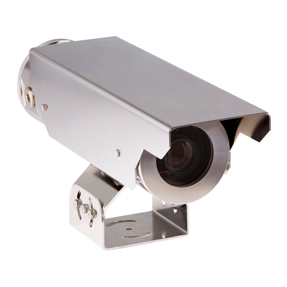
- Page 1 EX65 Explosion-Protected Camera VEN-650 Series Installation Manual Available from A1 Security Cameras www.a1securitycameras.com email: sales@a1securitycameras.com...
- Page 2 Available from A1 Security Cameras www.a1securitycameras.com email: sales@a1securitycameras.com...
-
Page 3: Table Of Contents
Day/Night submenu 33 8.4.5 Enhance / Dynamic Engine submenu 34 8.4.6 Color submenu 35 8.4.7 VMD submenu 35 Install menu structure 36 Bosch Security Systems, Inc. Installation Manual 2016.03 | 1.0 | F.01U.318.222 Available from A1 Security Cameras www.a1securitycameras.com email: sales@a1securitycameras.com... - Page 4 Installation of the Camera and Lens 42 10.4 Back Focus Adjustment 43 10.5 Replacement of the Mounting Cradle 43 Technical data 45 2016.03 | 1.0 | F.01U.318.222 Installation Manual Bosch Security Systems, Inc. Available from A1 Security Cameras www.a1securitycameras.com email: sales@a1securitycameras.com...
-
Page 5: Safety
Legal Information Copyright This manual is the intellectual property of Bosch Security Systems, Inc. and is protected by copyright. All rights reserved. Trademarks All hardware and software product names used in this document are likely to be registered trademarks and must be treated accordingly. -
Page 6: Important Safety Instructions
Electrical Code (NEC)), Canadian Electrical Code, Part I (also called CE Code or CSA C22.1), ® and all applicable local codes. Bosch Security Systems, Inc. accepts no liability for any damages or losses caused by incorrect or improper installation. Warning! INSTALL EXTERNAL INTERCONNECTING CABLES IN ACCORDANCE TO NEC, ANSI/NFPA70 (FOR US APPLICATION) AND CANADIAN ELECTRICAL CODE, PART I, CSA C22.1 (FOR CAN... -
Page 7: Important Notices
Electronic Surveillance - This device is intended for use in public areas only. U.S. federal law strictly prohibits surreptitious recording of oral communications. Environmental statement - Bosch has a strong commitment towards the environment. This unit has been designed to respect the environment as much as possible. - Page 8 CCTV system. Notice! Video loss is inherent to digital video recording; therefore, Bosch Security Systems cannot be held liable for any damage that results from missing video information. To minimize the risk of losing information, we recommend multiple, redundant recording systems, and a procedure to back up all analog and digital information.
-
Page 9: Fcc & Ices Compliance
Class I, Zone 1, AEx db IIB T6; Ex db IIB T6 X Zone 21, AEx tb IIIC T85°C Db Ex tb IIIC T85°C Db X Bosch Security Systems, Inc. Installation Manual 2016.03 | 1.0 | F.01U.318.222 Available from A1 Security Cameras... - Page 10 Relevant standards associated with the ATEX and IECEx certifications. EN 60079-0:2012+A11:2013 EN 60079-1:2014 EN 60079-31:2014 IEC 60079-0:2011 Edition 6 IEC 60079-1:2014 Edition 7 IEC 60079-31:2013 Edition 2 2016.03 | 1.0 | F.01U.318.222 Installation Manual Bosch Security Systems, Inc. Available from A1 Security Cameras www.a1securitycameras.com email: sales@a1securitycameras.com...
-
Page 11: Joint Information
EX65 Explosion-Protected Camera Safety | en Joint Information To obtain more information about the flameproof joints, please contact Bosch Security Systems. Joint-Threaded (All Models) Designation Pitch Full Threads Depth of Engaged Engagement Back Cover to Junction Box M 103 1.5 mm 7 minimum 14.5 mm... -
Page 12: Warranty / Limitation Of Liability
The foregoing warranty is subject to Buyer’s (i) promptly written claim and (ii) timely provision to BOSCH Security Systems of an opportunity to inspect and test the Product claimed to be defective. Such inspection may be on Buyer’s premises and/or BOSCH Security Systems may request the return of the Product at Buyer’s expense. -
Page 13: Customer Support And Service
EX65 Explosion-Protected Camera Safety | en 1.11 Customer Support and Service If this unit needs service, contact the nearest Bosch Security Systems Service Center for authorization to return and shipping instructions. Service Centers Telephone: 800-366-2283 or 585-340-4162 Fax: 800-366-1329 Email: cctv.repair@us.bosch.com... -
Page 14: Product Description
Verify that all the parts listed in the Parts List below are included. If any items are missing, notify your Bosch Security Systems Sales or Customer Service Representative. – Do not use this product if any component appears to be damaged. Please contact Bosch Security Systems in the event of damaged goods. –... -
Page 15: Parts List
Bottle of Jet-Lube® NCS-30 grease (as needed) Tube of Molykote® BG 20 grease (as needed) Tube of LA-CO Slic-Tite® Paste with PTFE (as needed) Bosch Security Systems, Inc. Installation Manual 2016.03 | 1.0 | F.01U.318.222 Available from A1 Security Cameras... -
Page 16: Planning
5.30 5.04 4.01 4.57 4.93 Figure 3.1: Front View 3/4-in. 60.0 71° 0.26 NPT x4 2.36 Ø Figure 3.2: Bottom view 2016.03 | 1.0 | F.01U.318.222 Installation Manual Bosch Security Systems, Inc. Available from A1 Security Cameras www.a1securitycameras.com email: sales@a1securitycameras.com... -
Page 17: Initial Preparations
Notice! To avoid excessive moisture saturation inside the housing, limit the amount of time that the unit housing is open. Bosch recommends that the unit housing be open for no more than five (5) minutes. Bosch Security Systems, Inc. -
Page 18: Installation Overview
– For ambient temperatures below –10 °C, use field wiring suitable for the minimum ambient temperature. 2016.03 | 1.0 | F.01U.318.222 Installation Manual Bosch Security Systems, Inc. Available from A1 Security Cameras www.a1securitycameras.com email: sales@a1securitycameras.com... - Page 19 EX65 Explosion-Protected Camera Installation Overview | en 19 Note: This product is serialized to ensure traceability. Bosch Security Systems, Inc. Installation Manual 2016.03 | 1.0 | F.01U.318.222 Available from A1 Security Cameras www.a1securitycameras.com email: sales@a1securitycameras.com...
-
Page 20: Connections
< 6 Ohm/1000 m (RG-11/U) Cable impedance 75 Ohm Agency rating Environmental Outdoor rated Temperature rating > 80 degrees C Sources Belden 9259 2016.03 | 1.0 | F.01U.318.222 Installation Manual Bosch Security Systems, Inc. Available from A1 Security Cameras www.a1securitycameras.com email: sales@a1securitycameras.com... -
Page 21: Alarm Cable Requirements
Video Bandwidth 5 Hz to 10 MHz Wavelength 850 nm Requirement Bosch LTC 4629 Fiber Receiver at controller end of system Terminal Connector Making the Connections All required connections are accessible by removing the rear end cap. Notice! Take care not to drop the end caps to prevent damage to the cap threads. - Page 22 4. Connect one lead of the power cable to terminal 3 and the other lead to terminal 4. Note: The power in terminals are polarity insensitive. 5. Connect the alarm out cable to terminal 5 and 6. 2016.03 | 1.0 | F.01U.318.222 Installation Manual Bosch Security Systems, Inc. Available from A1 Security Cameras www.a1securitycameras.com email: sales@a1securitycameras.com...
- Page 23 Set screws must not protrude from the threaded hole after tightening. See also – Installation Overview, page 18 – Installation Overview, page 18 Bosch Security Systems, Inc. Installation Manual 2016.03 | 1.0 | F.01U.318.222 Available from A1 Security Cameras www.a1securitycameras.com email: sales@a1securitycameras.com...
-
Page 24: Configuration
Using the supplied multi-use tool, loosen the three (3) bolts (Item 1, below) that hold the inner mounting bracket assembly. – Pull the assembly out of the housing. 2016.03 | 1.0 | F.01U.318.222 Installation Manual Bosch Security Systems, Inc. Available from A1 Security Cameras www.a1securitycameras.com email: sales@a1securitycameras.com... - Page 25 12. Tighten the set screws on the end cap using the supplied hex key. Set screws must not protrude from the threaded hole after tightening. See also – Installation Overview, page 18 Bosch Security Systems, Inc. Installation Manual 2016.03 | 1.0 | F.01U.318.222 Available from A1 Security Cameras www.a1securitycameras.com email: sales@a1securitycameras.com...
-
Page 26: Mounting
– Secure all cabling. The unit can be mounted to a compatible Bosch bracket with M6 bolts, or to any purpose-built bracket using M6 or 1/4 in.–20 bolts. Note: Ensure that a fabricated bracket is capable of supporting at least three times the weight of the system. - Page 27 Mounting | en Figure 7.1: EXTEGRA IP 9000/EX65 device to EXS-ADPT (1) to MIC Wall Mount Bracket (MIC-WMB) (2) Figure 7.2: EXS-ADPT Mount Bolt Hole Pattern Bosch Security Systems, Inc. Installation Manual 2016.03 | 1.0 | F.01U.318.222 Available from A1 Security Cameras...
-
Page 28: Installing The Sunshield
3. Tighten the supplied bolts to 2.0 N m (1.5 ft-lb) using a 7 mm wrench or the multi-use tool. 2016.03 | 1.0 | F.01U.318.222 Installation Manual Bosch Security Systems, Inc. Available from A1 Security Cameras www.a1securitycameras.com email: sales@a1securitycameras.com... -
Page 29: Operation
- To access the Main menu, press and hold the center key for less than 1 second. The Main menu appears on the monitor. If you are not happy with your changes, you can always recall the default values for the mode. Bosch Security Systems, Inc. Installation Manual 2016.03 | 1.0 | F.01U.318.222 Available from A1 Security Cameras www.a1securitycameras.com email: sales@a1securitycameras.com... -
Page 30: Menu Navigation Keys
Bilinx communications can only be disabled using the buttons on the camera. Disabled camera buttons When the Bilinx communications link is active, the buttons on the camera are disabled. 2016.03 | 1.0 | F.01U.318.222 Installation Manual Bosch Security Systems, Inc. Available from A1 Security Cameras www.a1securitycameras.com email: sales@a1securitycameras.com... -
Page 31: Main Menu Structure
Off - The camera output is optimized for connection to an analog system (matrix switcher or monitor). EXIT Returns to main menu. Bosch Security Systems, Inc. Installation Manual 2016.03 | 1.0 | F.01U.318.222 Available from A1 Security Cameras www.a1securitycameras.com email: sales@a1securitycameras.com... -
Page 32: Shutter/Agc Submenu
When active, some noise or spots may appear in the picture. This is normal camera behavior. It may also cause motion blur on moving objects. EXIT Returns to main menu. 2016.03 | 1.0 | F.01U.318.222 Installation Manual Bosch Security Systems, Inc. Available from A1 Security Cameras www.a1securitycameras.com email: sales@a1securitycameras.com... -
Page 33: Day/Night Submenu
On - the color burst remains active even in monochrome mode (required by some DVRs and IP encoders). EXIT Returns to main menu. Bosch Security Systems, Inc. Installation Manual 2016.03 | 1.0 | F.01U.318.222 Available from A1 Security Cameras www.a1securitycameras.com email: sales@a1securitycameras.com... -
Page 34: Enhance / Dynamic Engine Submenu
(Test on-site to ensure that it does benefit the application and is not distracting for operators of the security system.) EXIT Returns to main menu. 2016.03 | 1.0 | F.01U.318.222 Installation Manual Bosch Security Systems, Inc. Available from A1 Security Cameras www.a1securitycameras.com email: sales@a1securitycameras.com... -
Page 35: Color Submenu
VMD alarm. Motion above this level activates alarm. OSD alarm text Alphanumeric Text for on-screen display alarm (16 characters maximum). EXIT Returns to main menu. Bosch Security Systems, Inc. Installation Manual 2016.03 | 1.0 | F.01U.318.222 Available from A1 Security Cameras www.a1securitycameras.com email: sales@a1securitycameras.com... -
Page 36: Install Menu Structure
Displays the menus on the OSD in the chosen language. Spanish French German Portuguese Polish Italian Dutch Russian EXIT Returns to Install menu. 2016.03 | 1.0 | F.01U.318.222 Installation Manual Bosch Security Systems, Inc. Available from A1 Security Cameras www.a1securitycameras.com email: sales@a1securitycameras.com... -
Page 37: Lens Wizard Submenu
Alarm action None, Selects the operating mode of the camera when the alarm Mode 1 to 6, input is active. Mono Bosch Security Systems, Inc. Installation Manual 2016.03 | 1.0 | F.01U.318.222 Available from A1 Security Cameras www.a1securitycameras.com email: sales@a1securitycameras.com... -
Page 38: Connections Submenu
Compensation 0,1,2 . . .+15 Sets the level of cable compensation level EXIT Returns to Install menu. 2016.03 | 1.0 | F.01U.318.222 Installation Manual Bosch Security Systems, Inc. Available from A1 Security Cameras www.a1securitycameras.com email: sales@a1securitycameras.com... -
Page 39: Test Signal Submenu
Pattern Black, Grey, Selects pattern for all masks. White, Noise Mask 1, 2, 3, 4 Four different areas can be masked. Bosch Security Systems, Inc. Installation Manual 2016.03 | 1.0 | F.01U.318.222 Available from A1 Security Cameras www.a1securitycameras.com email: sales@a1securitycameras.com... -
Page 40: Defaults Submenu
Restores all settings of the six modes to their default (factory) values. Select YES, then press the Menu/Select button to restore all values. When completed, the message RESTORED! appears. 2016.03 | 1.0 | F.01U.318.222 Installation Manual Bosch Security Systems, Inc. Available from A1 Security Cameras www.a1securitycameras.com email: sales@a1securitycameras.com... -
Page 41: Troubleshooting
Customer Service If a fault cannot be resolved, please contact your supplier or system integrator, or go directly to Bosch Security Systems Customer Service. Camera Operation The following table is intended to help you identify the causes of malfunctions and correct them when possible. -
Page 42: Maintenance
3. Reinstall the mounting bolt with a #3 Phillips screwdriver. Tighten the camera mounting bolt to 4.5 N m (3.3 ft/lb). 2016.03 | 1.0 | F.01U.318.222 Installation Manual Bosch Security Systems, Inc. Available from A1 Security Cameras www.a1securitycameras.com email: sales@a1securitycameras.com... -
Page 43: Back Focus Adjustment
8. Close the side door panel. 10.5 Replacement of the Mounting Cradle 1. Disconnect power from the unit and, optionally, remove all connections. Bosch Security Systems, Inc. Installation Manual 2016.03 | 1.0 | F.01U.318.222 Available from A1 Security Cameras www.a1securitycameras.com email: sales@a1securitycameras.com... - Page 44 5. Install a new mounting cradle in reverse of installation and tighten the seven (7) M4 bolts to 2.0 N m (1.5 ft/lb). 6. Finish installation as described in Mounting, page 26. 2016.03 | 1.0 | F.01U.318.222 Installation Manual Bosch Security Systems, Inc. Available from A1 Security Cameras www.a1securitycameras.com email: sales@a1securitycameras.com...
-
Page 45: Technical Data
Technical data For product specifications, see the datasheet for your camera, available on the appropriate product pages of the Online Product Catalog at www.boschsecurity.com. Bosch Security Systems, Inc. Installation Manual 2016.03 | 1.0 | F.01U.318.222 Available from A1 Security Cameras... - Page 46 Available from A1 Security Cameras www.a1securitycameras.com email: sales@a1securitycameras.com...
- Page 47 Available from A1 Security Cameras www.a1securitycameras.com email: sales@a1securitycameras.com...
- Page 48 Bosch Security Systems, Inc. 1706 Hempstead Road Bosch Sicherheitssysteme GmbH Lancaster, PA, 17601 Robert-Bosch-Ring 5 85630 Grasbrunn www.boschsecurity.com Germany © Bosch Security Systems, Inc., 2016 www.boschsecurity.com Available from A1 Security Cameras www.a1securitycameras.com email: sales@a1securitycameras.com...