Advertisement
Quick Links
RG79V995H03
Package Air-Conditioner
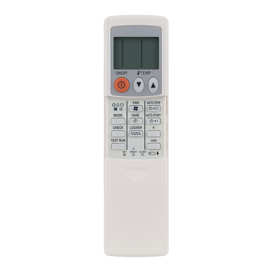
Wireless remote controller kit PAR-SL94B-E
Installation Manual
This manual describes the installation for wireless remote controller kit of the Mitsubishi ceiling suspended series package
air-conditioner. Read this manual carefully.
Safety Precautions
●
Read these "Safety Precautions" thoroughly and install securely.
●
Precautions are classified using the following symbols depending on the extent and type of danger by erroneous handling.
WARNING
Erroneous handling can cause death or serious injury.
CAUTION
Erroneous handling can cause personal injury or damage.
●
After using this manual, be sure to pass it to the customer together with the instruction manual provided with the indoor unit.
Ask the customer to keep this installation manual and the instruction manual in a handy place, and to show them to the
engineer when the air-conditioner is moved or repaired. Also ask the customer to pass them to any new user.
Ask a dealer or specialist to install the unit.
• Incomplete installation could cause electric shock, fire, etc.
Securely install the unit in a place that can with stand the
weight.
• Otherwise, the unit could fall, which could cause injury.
Never modify the unit or repair it by yourself.
• Modification or incorrect repair could cause electric shock,
fire, etc. Consult the dealer from whom you purchased the unit.
Do not move the unit by yourself.
• Incomplete installation could cause electric shock, fire,
etc. Ask the dealer or a specialist for installation.
Do not install the unit in a place where flammable gas could leak.
• If gas leaks or accumulates around the unit, it could cause
ignition, explosion, etc.
Do not use the unit in an abnormal environment.
• Usage in a place where there is much oil (including machine
oil), steam, sulfide gas, etc. could greatly degrade its perfor-
mance or damage components.
Take sufficient countermeasures against noise when the unit is installed in hospital, communication office, etc.
• This unit could malfunction when affected by inverter equipment, private electric generator, high-frequency medical instru-
ments, radio communication devices, etc. Also, this unit could adversely affect medical instruments, communication devices,
etc., thus interfering with human medical treatment, or causing disturbance in broadcast pictures or noise.
When doing wiring, make sure that wires are not subject
to tension.
• Tension on wires could disconnect them, or cause heat, fire, etc.
Do not rinse this unit with water.
• Doing so could cause fault, electric shock, etc.
Do not install the unit in a place where the ambient temperature
is over 40°C or below 0°C, or exposed to direct sunlight.
• Installing in such a place could cause deformation, fault, etc.
Making Sure of Components
Make sure that the following components, along with this manual, are packed in the box.
Component
Wireless remote controller receiver
Wireless remote controller
Remote control holder
"AAA" LR03 alkaline batteries
4.1×16 wood screws
Cord retaining clips
Connection cord fixing seal (12×30 size)
How to Install
W Be sure to turn the power off before installing.
1 Removing the intake grille and the right side panel
• Slide the catch holding the intake grille backwards to open the grille. Remove the screw holding the side panel.
Remove the side panel support hanger, and then slide the side panel forward to remove it.
Slide
Slide
Catch retaining the intake grille
2 Removing the existing brand label case
• Remove the brand label case (name plate with
MITSUBISHI ELECTRIC) from the bottom right
of the unit. If it is difficult to remove the case,
use a flat-blade screwdriver, etc., taking care not to
damage the panel.
3 Installing to the indoor unit
• Pass the receiver board connector through the right side of the square hole to which the brand label case
was attached and then pull the connector and cord through the slit in the right side of the bottom panel.
• Fit the receiver into the square hole where the brand label case was attached.
Slit
WARNING
Securely install the unit, referring to this installation manual.
• Incomplete installation could cause electric shock, fire,
etc.
All accessories must be installed by an authorized technician.
• The user must not try to install accessories. Improperly
installed accessories can cause water leakage, electric
shock or fire. Shortage in electrical circuit capacity or
incomplete construction could cause fire, etc.
Securely connect the specified remote control cord, and
fix it so that the terminal connector is free from any external
force via the cord.
• Incomplete connection or fixing could cause heat, fire, etc.
CAUTION
Do not install the unit in a bathroom, kitchen, etc. where a
great amount of steam is generated.
• Avoid installing in a wall where condensation occurs. Insta-
lling in such a place could cause a fault, electric shock, etc.
Do not install the unit in a place where acid solution, alkaline
solution, special spray, etc. are frequently used.
• Installing in such a place could cause fault, electric shock, etc.
Do not touch circuit boards with hands or tools, or allow
dust to adhere to them.
• Failure to do so could cause fault, fire, etc.
Do not operate buttons with wet hands.
• Failure to do so could cause fault, electric shock, etc.
Do not push buttons with sharp objects.
• Failure to do so could cause fault, electric shock, etc.
Q'ty
1
1
1
2
2
2
1
hole for side panel
side panel
support hanger
support hanger
Side panel
Slide forward
Slide forward
Remove the screw holding the side panel
Panel
Case
Panel
Retaining clip
4 Laying out the lead wire
• Pass the lead wire for receiver through the retaining clips.
• Fix the lead wire for receiver with the clips on the ceiling side
of the unit.
5 Removing the beam and the electrical box cover
• Remove the beam.
• Loosen the two screws at the bottom of the electrical box cover,
and then slide the cover to the left to remove it.
• Pull down the electrical box.
Also on the
Electrical box fixing screw
{
opposite side
Electrical box cover fixing screw
Clamps
Clamps
7 Reinstalling the removed components
• Reinstall the removed components in reverse order. (The brand label case is not needed.)
8 Remote control holder
• To install the wireless remote controller on a wall, first attach the remote control holder to a wall.
1
3
2
NOTE : The remote signal will reach the receiver over a distance of approx. 7m in a straight line and approx. 45°
left or right. If the infrared receiver is affected by fluorescent light (especially, inverter type), it may not be
able to receive the signal. Take this into consideration when installing fluorescent lights or replacing them.
Model Select
This remote controller needs model number setting before use.
Set the model number in the following order.
Without setting the air conditioner will not work property.
(The factory setting of model number is "001".)
1 Insert batteries.
2 Press the SET button with something sharp at the end.
MODE SELECT blinks and Model No. is lighted.
3 Press the temp
button to set the Model Number.
4 Press the SET button with something sharp at the end.
MODE SELECT and Model No. are lighted for 3 seconds, then turned off.
Indoor Unit Model
(H/P)/(C/O)
Outdoor
Heat pump
PCA-RP. KA
Outdoor
Cooling only
Cooling only
PC-KAK
Outdoor: Separate
heating and cooling
Outdoor: Simultaneous
PCFY-P. KM
heating(PURY) and cooling
Indoor: Cooling only
5
Pair Number Setting
• This is the setting to specify the unit to operate with the wireless remote controller.
• Make setting for J41, J42 (Jumper wire) of indoor controller board and the pair number of wireless remote controller.
• The pair number setting is available with the 4 patterns as shown in the following table. Make setting for the pair number
(J41, J42) of indoor controller board and the pair number of wireless remote controller which is used
as shown in the following table. *The initial setting is Pair No. "0".
1 Press the SET button with something sharp at the end.
Start this operation from the status of remote controller display turned off.
blinks and Model No. is lighted.
MODEL SELECT
2 Press the
min
button twice continuously. Pair No. "0" blinks.
3 Press the temp
button to set the pair number you want to set.
4 Press the SET button with something sharp at the end.
Set pair number is lighted for 3 seconds then turned off.
A Pair No. of wireless remote controller Indoor PC board
0
Initial setting
1
2
3 ~ 9
Cut J41, J42
CN90
* The positions of the connectors may be
Jumper wire (J41, J42)
Clips on the ceiling side
Retaining clip
Beam
CN90
Bush
* The positions of the connectors may be different according to the model.
Please refer to the wiring diagram to confirm the positions of the connectors.
Fitting remote control into holder
1 Fix the remote control holder to the wall using
the 2 wood screws provided.
2 Insert the remote control into the holder.
3 Push the remote control against the wall.
Removing remote control
●
Pull the top of remote control forward.
MODEL SELECT
ON/OFF
FAN
Model No.
MODE
VANE
CHECK LOUVER
001
TEST RUN
033
SET
RESET
2 4
035
225
001
033
MODEL SELECT
ON/OFF
Cut J41
FAN
Cut J42
MODE
VANE
CHECK LOUVER
TEST RUN
SET
RESET
CLOCK
1 4
different according to the model.
Please refer to the wiring diagram to
confirm the positions of the connectors.
Electrical box cover
Model
Number
3
TEMP
AUTO STOP
AUTO START
h
min
CLOCK
A
3
TEMP
AUTO STOP
AUTO START
h
min
2
Advertisement

Related Manuals for Mitsubishi Electric PAR-SL94B-E


Summary of Contents for Mitsubishi Electric PAR-SL94B-E
- Page 1 • Fix the lead wire for receiver with the clips on the ceiling side Package Air-Conditioner of the unit. Wireless remote controller kit PAR-SL94B-E Retaining clip Installation Manual This manual describes the installation for wireless remote controller kit of the Mitsubishi ceiling suspended series package air-conditioner.
- Page 2 RG79V995H03 Test Run Measure an impedance between the power supply terminal block on the outdoor unit Setting the unit numbers Set “00” as the unit number when setting function from Table 4. and the ground with a 500V Megger and check that it is equal to or greater than 1.0 M". When setting function from Table 5.