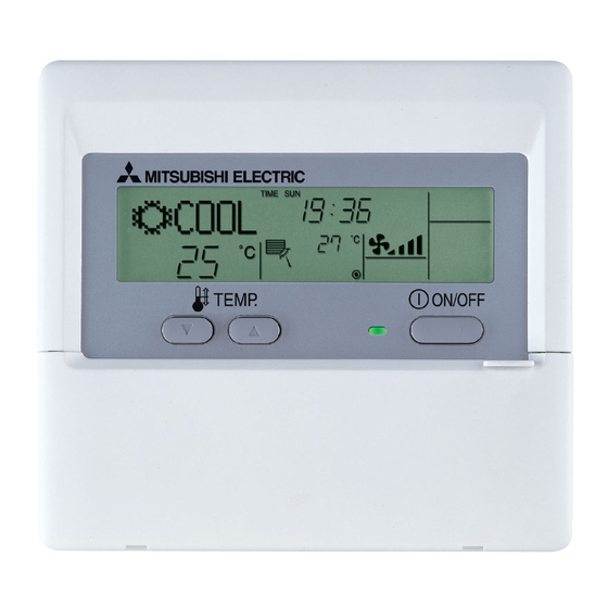
Mitsubishi Electric PAR-21MAA Installation Manual
City multi control system and mitsubishi mr. slim air conditioners ma deluxe remote controller
Hide thumbs
Also See for PAR-21MAA:
- Instruction book (146 pages) ,
- Installation manual (104 pages) ,
- Technical manual (76 pages)
Advertisement
WT04465X01
GB
CITY MULTI Control System
and Mitsubishi Mr. SLIM Air Conditioners
MA Deluxe Remote Controller
Installation Manual
This instruction manual describes how to install the MA Remote Controller for Mitsubishi Building Air Conditioning System, direct expansion type CITY
MULTI air conditioner indoor units ("-A" type and later), and Mitsubishi Mr. SLIM packaged air conditioners. Please read this manual thoroughly and
install the remote controller accordingly. For information on how to wire and install the air conditioning units, refer to the installation manual. After the
installation, hand over this manual to users.
1 Safety Precautions
G Read these Safety Precautions and perform installation work accordingly.
G The following two symbols are used to dangers that may be caused by incorrect use and their degree:
WARNING
This symbol denotes what could lead to serious injury or death if you misuse the PAR-21MAA.
CAUTION
This symbol denotes what could lead to a personal injury or damage to your property if you misuse the PAR-21MAA.
G After reading this installation manual, give it and the indoor unit installation manual to the end user.
G The end user should keep this manual and the indoor unit installation manual in a place where he or she can see it at anytime. When someone moves
or repairs the PAR-21MAA, make sure that this manual is forwarded to the end user.
Ask your dealer or technical representative to install the unit.
Any deficiency caused by your own installation may result in an electric shock
or fire.
Install in a place which is strong enough to withstand the weight of the
PAR-21MAA.
Any lack of strength may cause the PAR-21MAA to fall down, resulting in
personal injury.
Firmly connect the wiring using the specified cables. Carefully check
that the cables do not exert any force on the terminals.
Improper wiring connections may produce heat and possibly a fire.
Never modify or repair the PAR-21MAA by yourself.
Any deficiency caused by your modification or repair may result in an electric
shock or fire.
Consult with your dealer about repairs.
Do not install in any place exposed to flammable gas leakage.
Flammable gases accumulated around the body of PAR-21MAA may cause
an explosion.
Do not use in any special environment.
Using in any place exposed to oil (including machine oil), steam and sulfuric
gas may deteriorate the performance significantly or give damage to the com-
ponent parts.
When installing the remote controller in a hospital or communication
facility, take ample countermeasures against noise.
Inverters, emergency power supply generators, high-frequency medical equip-
ment, and wireless communication equipment can cause the remote control-
ler to malfunction or to fail. Radiation from the remote controller may effect
communication equipment and prevent medial operations on the human body
or interfere with image transmission and cause noise.
Wire so that it does not receive any tension.
Tension may cause wire breakage, heating or fire.
Completely seal the wire lead-in port with putty etc.
Any dew, moisture, insects entering the unit may cause an electric shock or a
malfunction.
Do not install in any place at a temperature of more than 40
°
than 0
C or exposed to direct sunlight.
Doing so may cause deformation or malfunction.
2 Confirming the Supplied Parts
Confirm that the box includes the following parts, in addition to this installation manual:
1. Remote controller (cover, body) ..................................................................................... 1
2. Cross recessed pan head screw (M4 × 30) .................................................................... 2
3. Wood screw (4.1 × 16, used for directly hooking to the wall) ......................................... 2
4. Caution label (in 12 languages) ..................................................................................... 1
*1 For the remote control, obtain a 2-core cable between 0.3 and 1.25 mm
*2 PAC-YT32PTA cannot be connected.
WARNING
Ensure that installation work is done correctly following this installa-
tion manual.
Any deficiency caused by installation may result in an electric shock or fire.
All electrical work must be performed by a licensed technician, accord-
ing to local regulations and the instructions given in this manual.
Any lack of electric circuit or any deficiency caused by installation may result
in an electric shock or fire.
Do not move and re-install the PAR-21MAA yourself.
Any deficiency caused by installation may result in an electric shock or fire.
Ask your distributor or special vendor for moving and installation.
To dispose of this product, consult your dealer.
CAUTION
Do not apply AC100V or AC200V to the remote controller. The maximum
voltage that can be applied to the remote controller is 12V.
The remote controller may be damaged or may generate heat and cause a
fire.
Do not install in any steamy place such a bathroom or kitchen.
Avoid any place where moisture is condensed into dew. Doing so may cause
an electric shock or a malfunction.
Do not install in any place where acidic or alkaline solution or special
spray are often used.
Doing so may cause an electric shock or malfunction.
Use standard wires in compliance with the current capacity.
A failure to this may result in an electric leakage, heating or fire.
Do not touch any control button with your wet hands.
Doing so may cause an electric shock or a malfunction.
Do not wash with water.
Doing so may cause an electric shock or a malfunction.
Do not press any control button using a sharp object.
Doing so may cause an electric shock or a malfunction.
°
C or less
2
at the site.
PAR-21MAA
Remote controller cover
Remote controller body
1
Advertisement
Table of Contents

Related Manuals for Mitsubishi Electric PAR-21MAA


Summary of Contents for Mitsubishi Electric PAR-21MAA
-
Page 1: Safety Precautions
This symbol denotes what could lead to serious injury or death if you misuse the PAR-21MAA. CAUTION This symbol denotes what could lead to a personal injury or damage to your property if you misuse the PAR-21MAA. G After reading this installation manual, give it and the indoor unit installation manual to the end user. -
Page 2: How To Install
3 How To Install Choose a place in which to install the remote controller (switch box). Be sure to observe the following steps: Extra space (1) Temperature sensors are provided with both the remote controller and the indoor units. When using the External size around remote of remote... -
Page 3: Ventilation Setting
During test run, the RUN lamp remains on. BACK MONITOR/SET CHECK TEST tion of the indoor unit installation manual. PAR-21MAA CLOCK OPERATION CLEAR [TEST] button 5 Ventilation Setting Make this setting only when interlocked operation with LOSSNAY is necessary with CITY MULTI models. - Page 4 4 If registration is unnecessary, end registration by pressing and holding down the [FILTER] and [ ] buttons at the same time for two seconds. If a new LOSSNAY must be registered, go to step 1. Registration procedure. If you want to confirm another LOSSNAY, go to step 2. Confirmation procedure.
-
Page 5: Function Selection
(“MODE MENU ON/OFF FILTER Timer function setting (“WEEKLY TIMER”) See [4]-3. (3) SELECTION”) BACK MONITOR/SET CHECK TEST PAR-21MAA CLOCK OPERATION CLEAR Contact number setting for error situation (“CALL.”) See [4]-3. (4) Press the E button. Press the D button. →... - Page 6 FILTER (Buttons C and D operation) BACK MONITOR/SET CHECK TEST (Specified indoor unit → 5 Registration (Press button E.) PAR-21MAA CLOCK OPERATION CLEAR Change Fan operation) refrigerant address and unit 6 Mode No. Selection → 02 (Room temperature detection position) address No.?
- Page 7 [Procedure] (Set only when change is necessary.) 1 Check the set contents of each mode. When the set contents of a mode were changed by function selection, the functions of that mode also change. Check the set contents as described in steps 2 to 7 and change the setting based on the entries in the Table 1 check field. For the factory settings, refer to the indoor unit installation manual. 2 Set the remote controller to Off.
-
Page 8: Self Check
Self check Retrieve the error history of each unit using the remote controller. 1 Switch to the self check mode. 2 Set the address or refrigerant address No. you want to self check. When the H [CHECK] button is pressed twice successively When the F [ TEMP.