Mitsubishi Electric MELSEC Q Series User Manual
Hide thumbs
Also See for MELSEC Q Series:
- User manual (834 pages) ,
- Reference manual (674 pages) ,
- Programming manual (624 pages)

Related Manuals for Mitsubishi Electric MELSEC Q Series


Summary of Contents for Mitsubishi Electric MELSEC Q Series
- Page 1 CC-Link/LT Master Module User's Manual -QJ61CL12 Downloaded from ManualsNet.com search engine...
- Page 2 Downloaded from ManualsNet.com search engine...
-
Page 3: Safety Precautions
SAFETY PRECAUTIONS (Read these precautions before using this product.) Before using this product, please read this manual and the relevant manuals carefully and pay full attention to safety to handle the product correctly. The precautions given in this manual are concerned with this product only. For the safety precautions of the programmable controller system, refer to the user's manual for the CPU module used. - Page 4 [Design Precautions] CAUTION ● Do not install the control lines or communication cables together with the main circuit lines or power cables. Keep a distance of 100mm or more between them. Failure to do so may result in malfunction due to noise. [Installation Precautions] CAUTION ●...
- Page 5 [Wiring Precautions] WARNING ● Shut off the external power supply (all phases) used in the system before wiring. Failure to do so may result in electric shock or damage to the product. [Wiring Precautions] CAUTION ● Prevent foreign matter such as dust or wire chips from entering the module. Such foreign matter can cause a fire, failure, or malfunction.
- Page 6 [Startup and Maintenance Precautions] CAUTION ● Do not disassemble or modify the modules. Doing so may cause failure, malfunction, injury, or a fire. ● Use any radio communication device such as a cellular phone or PHS (Personal Handy-phone System) more than 25cm away in all directions from the programmable controller. Failure to do so may cause malfunction.
-
Page 7: Conditions Of Use For The Product
CONDITIONS OF USE FOR THE PRODUCT (1) Mitsubishi programmable controller ("the PRODUCT") shall be used in conditions; i) where any problem, fault or failure occurring in the PRODUCT, if any, shall not lead to any major or serious accident; and ii) where the backup and fail-safe function are systematically or automatically provided outside of the PRODUCT for the case of any problem, fault or failure occurring in the PRODUCT. -
Page 8: Revisions
Japanese manual version SH-080344-K This manual confers no industrial property rights or any rights of any other kind, nor does it confer any patent licenses. Mitsubishi Electric Corporation cannot be held responsible for any problems involving industrial property rights which may occur as a result of using the contents noted in this manual. -
Page 9: Introduction
INTRODUCTION Thank you for purchasing the Mitsubishi MELSEC-Q series programmable controllers. This manual describes the functions and programming of the QJ61CL12 CC-Link/LT master module (hereafter abbreviated as QJ61CL12). Before using this product, please read this manual and the relevant manuals carefully and develop familiarity with the functions and performance of the MELSEC-Q series programmable controller to handle the product correctly. -
Page 10: Relevant Manuals
RELEVANT MANUALS (1) CPU module user's manual Manual name Description <manual number (model code)> QCPU User's Manual Specifications of the hardware (CPU modules, power supply modules, (Hardware Design, Maintenance and Inspection) base units, batteries, and memory cards), system maintenance and inspection, <SH-080483ENG, 13JR73>... - Page 11 Memo Downloaded from ManualsNet.com search engine...
-
Page 12: Table Of Contents
CONTENTS CONTENTS SAFETY PRECAUTIONS ............. 1 CONDITIONS OF USE FOR THE PRODUCT . - Page 13 4.5.1 Connecting a dedicated flat cable connector ........4.5.2 Connecting a VCTF cable connector/flexible cable connector.
-
Page 14: Manual Page Organization
MANUAL PAGE ORGANIZATION In this manual, pages are organized and the symbols are used as shown below. The following illustration is for explanation purpose only, and should not be referred to as an actual documentation. "" is used for screen names and items. The chapter of the current page is shown. -
Page 15: Terms
TERMS Unless otherwise specified, this manual uses the following terms. Term Description QJ61CL12 The abbreviation for the QJ61CL12 CC-Link/LT master module A station that controls a data link system Master station One master station is required for one system. A remote station, such as CL2X8-D1B2 and CL2Y8-TP1B2, that exchanges I/O signals (bit data) Remote I/O station with an external device A remote station that exchanges I/O signals (bit data) and I/O data (word data) with an external... -
Page 16: Chapter 1 Characteristics Of Cc-Link/Lt System
CHAPTER 1 CHARACTERISTICS OF CC-Link/LT SYSTEM This chapter describes the features and application of a CC-Link/LT system. CC-Link/LT System A CC-Link/LT system is a wire-saving network system used inside a control panel and equipment, making complex wiring unnecessary and preventing incorrect wiring. This system simplifies wiring among sensor, actuator, and controller, providing advanced functionalities such as high- speed response time. -
Page 17: Features
CHAPTER 1 CHARACTERISTICS OF CC-Link/LT SYSTEM Features This section describes features of CC-Link/LT. (1) Easy connection/disconnection of communication cable By using dedicated connectors, communication cables can be connected/disconnected with one simple motion. This allows modules to be easily extended, added, and changed. Using dedicated flat cables, VCTF cables, and flexible cables leads to reduction in wiring work and cable cost. -
Page 18: Chapter 2 System Configuration
CHAPTER 2 SYSTEM CONFIGURATION This chapter describes a CC-Link/LT system configuration. Overall Configuration To one master station, up to 64 remote stations can be connected when the following conditions are met. Item Specifications Remarks ⎯ Transmission speed 2.5Mbps 625kbps 156kbps ⎯... -
Page 19: Applicable System
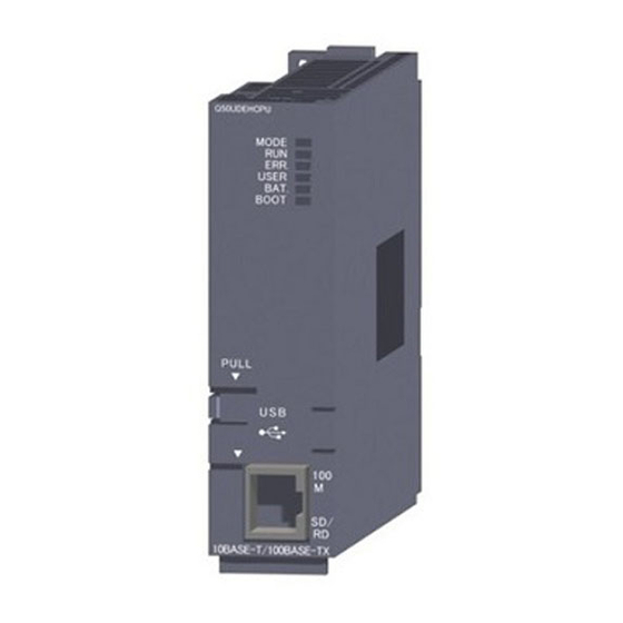
CHAPTER 2 SYSTEM CONFIGURATION Applicable System This section provides information on the available CPU module and notes on system configuration. 2.2.1 Applicable Modules and the Number of Available Modules (1) Applicable modules and base units, and No. of modules (a) When mounted with a CPU module The table below shows the CPU modules and base units applicable to the QJ61CL12 and quantities for each CPU model. - Page 20 Applicable CPU module Base unit (*2) No. of modules (*1) CPU type CPU model Main base unit Extension base unit Q03UDECPU Q04UDEHCPU Q06UDEHCPU Q10UDEHCPU Universal model QCPU Q13UDEHCPU Up to 64 Q20UDEHCPU Q26UDEHCPU Q50UDEHCPU Q100UDEHCPU Safety CPU QS001CPU × × (*3) Q06CCPU-V C Controller module Q06CCPU-V-B...
- Page 21 CHAPTER 2 SYSTEM CONFIGURATION (2) Application to multiple CPU system When using the QJ61CL12 in a multiple CPU system, refer to the following. QCPU User's Manual (Multiple CPU System) (a) QJ61CL12 available for multiple CPU system The function version of the first released QJ61CL12 is B, and it supports multiple CPU systems. (b) Parameters of intelligent function modules Write the parameters of intelligent function modules to only the control CPU of QJ61CL12.
-
Page 22: Precautions For System Configuration
2.2.2 Precautions for system configuration (1) QJ61CL12 position Install the QJ61CL12 on either end of the trunk line. Since T-branch connection is available, the module can be apparently installed on any position on the trunk line. However, the trunk line length is defined as the length between the terminating resistors. Master station Terminating resistor Branch line length... - Page 23 CHAPTER 2 SYSTEM CONFIGURATION (3) Installation conditions of a dedicated power supply and a power supply adapter The installation conditions of the power supplies depend on the connected devices and wiring length. For the conditions, refer to the user’s manual for the dedicated power supply or the power supply adapter. Always connect a dedicated power supply or a power supply adapter to the trunk line.
- Page 24 (b) At momentary power failure of remote I/O modules If momentary power failure occurs in the power supplied to remote I/O modules (24VDC), incorrect input may occur. • Cause The hardware of a remote I/O module internally converts 24VDC (module power supply) into 5VDC. If momentary power failure occurs in a remote I/O module, (Time until the internal power of the remote I/O module (5VDC) turns off) >...
- Page 25 CHAPTER 2 SYSTEM CONFIGURATION (5) Duplication of a remote station number • If remote station numbers are duplicated, the duplicating stations may cause malfunction (incorrect input/ output). Check that the remote station numbers are not duplicated before powering on the system. Remote Remote station...
-
Page 26: Check Methods Of Serial Number And Function Version
Check Methods of Serial Number and Function Version The serial No. and function version of the QJ61CL12 can be confirmed on the rating plate, the front of the module and GX Developer's system monitor. (1) How to check function version and serial No. of QJ61CL12 (a) Confirming the serial number on the rating plate The rating plate is situated on the side face of the QJ61CL12. - Page 27 CHAPTER 2 SYSTEM CONFIGURATION (c) Confirming the serial number on the system monitor (Product Information List) Open the monitor window in GX Developer. [Diagnostics] [System monitor] button Function version Serial No. Production number • Production number display Since the QJ61CL12 does not support the production number display, "-" is displayed. The serial No.
-
Page 28: Chapter 3 Specifications
CHAPTER 3 SPECIFICATIONS This chapter describes specifications of the QJ61CL12. For the general specifications of the QJ61CL12, refer to the following. QCPU User's Manual (Hardware Design, Maintenance and Inspection) Downloaded from ManualsNet.com search engine... -
Page 29: Performance Specifications
CHAPTER 3 SPECIFICATIONS Performance Specifications The following table lists the performance specifications of the QJ61CL12. Item Specifications Point mode 4-point mode 8-point mode 16-point mode Maximum link points 256 points 512 points 1024 points (the same I/O address used) (512 points) (1024 points) (2048 points) Link points per station... -
Page 30: Network Wiring Specifications
3.1.1 Network wiring specifications The following table lists the network wiring specifications of CC-Link/LT. Item Specifications Remarks Transmission speed 2.5Mbps 625kbps 156kbps ⎯ ⎯ Station-to-station distance No limit Maximum number of modules on a ⎯ branch line The cable length between terminating Trunk line length 100m 500m... -
Page 31: I/O Signals To/From Cpu Module
CHAPTER 3 SPECIFICATIONS I/O Signals to/from CPU Module This section describes I/O signals of the QJ61CL12 for the CPU module. Input signals (X) are assigned to the remote input area, and output signals (Y) are assigned to the remote output area. No special I/O signal is required to operate the QJ61CL12. -
Page 32: I/O Signals In 8-Point Mode Setting
3.2.2 I/O signals in 8-point mode setting The following tables list I/O signals in 8-point mode. Remote input (X) Input number XnF to Xn0 Station No.2 Station No.1 X(n+1F)F to X(n+1F)0 Station No.64 Station No.63 Remote output (Y) Output number YnF to Yn0 Station No.2 Station No.1... -
Page 33: Buffer Memory
CHAPTER 3 SPECIFICATIONS Buffer Memory The buffer memory is used for data communication between the QJ61CL12 and the CPU module and is read or written by GX Developer or sequence programs. When the system is powered off or the CPU module is reset, the contents of the buffer memory will return to the default setting. - Page 34 (2) Faulty station information (buffer memory address: 4 to 7 (Un\G4 to 7)) The data link status of remote stations is stored. Address (decimal) Station No.16 Station No.15 Station No.14 Station No.3 Station No.2 Station No.1 Station No.32 Station No.31 Station No.30 Station No.19 Station No.18...
- Page 35 CHAPTER 3 SPECIFICATIONS (5) External switch information (buffer memory address: 17 (Un\G17)) The switch status of the number of occupied I/O points setting, transmission speed setting, point mode setting, and test mode are stored. Name Description Status of operation setting switch SW3 to SW1 Number of occupied I/O b2 to b0 000: 16 pts.
- Page 36 (8) Data link last station information (buffer memory address: 20 (Un\G20)) The last station number of data-link-available remote stations is stored. Name Description b6 to b0 Data link last station number The last station number of data-link-available remote stations is stored. ⎯...
-
Page 37: Point Mode Setting And The Number Of Occupied I/O Points Setting
CHAPTER 3 SPECIFICATIONS Point Mode Setting and the Number of Occupied I/O Points Setting This section describes concepts of the point mode setting and the number of occupied I/O points setting required for system configuration. The number of points that the master station can control per remote station occupying one station is set for the point mode setting. - Page 38 • Even if the same remote module is used, the number of occupied stations varies depending on the point mode setting. When 4-point mode is set for a 16-point module, four stations are occupied. In the same way, two stations are occupied in 8-point mode and one station is occupied in 16-point mode. •...
- Page 39 CHAPTER 3 SPECIFICATIONS • I/O number assignment is described using the I/O assignment table in APPENDICES. The following table lists the I/O number assignment when 8-point mode is set and 64 points is set for the number of occupied I/O points in the system shown in the example on the previous page. Station Station Model...
-
Page 40: Last Station Number Setting
Last Station Number Setting The last station number is set to perform data link up to the last remote station in connection with the network and not to perform data link with unconnected stations. This setting is optional but useful to optimize link scan time. For the setting, Page 47, Section 4.4. -
Page 41: Data Link Processing Time
CHAPTER 3 SPECIFICATIONS Data Link Processing Time This section describes the link scan time, transmission delay time, and automatic return time. 3.7.1 Link scan time The link scan time of CC-Link/LT is described as below. [Link scan time (LS)] LS = a + (b × N) × c [µs] a: Constant b: Constant c: Constant... -
Page 42: Transmission Delay Time
3.7.2 Transmission delay time The transmission delay time (time that data reaches to a destination) is described as below. (1) Master station Remote station (Input) ← The following formula calculates the time after a signal is input to a remote station until the CPU module device (X) turns on (off). -
Page 43: Automatic Return Time
CHAPTER 3 SPECIFICATIONS 3.7.3 Automatic return time The automatic return time is the time taken for a module recovered from an error to automatically restart data link. [Calculation formula] 37401 + A + B + C + LS [µs] A: Constant B: Constant C: Constant LS: Link scan time (... -
Page 44: Chapter 4 Procedure Before Operation
CHAPTER 4 PROCEDURE BEFORE OPERATION This chapter describes a procedure from module installation to a data link start. Procedure Before Operation The following steps should be performed for data link of the CC-Link/LT. Start Mount QJ61CL12 on base unit. Install a remote module into a control panel or equipment. - Page 45 CHAPTER 4 PROCEDURE BEFORE OPERATION Continued from previous page Check operation with LEDs (QJ61CL12) When the data link is normal: The L RUN LED is on. When the data link is faulty : The L ERR. LED is on or flashing. When the setting is incorrect: The ERR.
-
Page 46: Installation
Installation This section describes handling precautions on the steps from the unpacking to the installation of the QJ61CL12. (1) Setting method For details on the implementation of the module, refer to the following. QCPU User's Manual (Hardware Design, Maintenance and Inspection) (2) Handling precautions •... -
Page 47: Part Names
CHAPTER 4 PROCEDURE BEFORE OPERATION Part Names This section describes the names of the parts, LED indications and setting methods of the switches. Downloaded from ManualsNet.com search engine... - Page 48 Name Description LED indicator An indicator to check the module status Description ON: Normal module operation OFF: Hardware failure ON: Incorrect switch setting ERR. Flashing: Switch setting changed during operation <Normal operation> ON: Data link being executed OFF: Data link stopped L RUN <In test mode>...
-
Page 49: Switch Setting Of Intelligent Function Module
CHAPTER 4 PROCEDURE BEFORE OPERATION Switch Setting of Intelligent Function Module The switch setting of the intelligent function module is performed in "I/O assignment settings" of GX Developer. (1) Setting Item Set the intelligent function module switches in 16-bit data. When the switches are not set, Switch 1 is set to "0"... - Page 50 (2) Operating procedure Start settings on the I/O assignment setting window of GX developer. [Parameter] [PLC Parameter] [I/O Assignment] (a) I/O assignment setting window Set the following to the slot where QJ61CL12 is installed. The "Type" setting is indispensable; set other items as needed. Item Description Type...
-
Page 51: Connecting Modules Using Connection Cables
CHAPTER 4 PROCEDURE BEFORE OPERATION Connecting Modules Using Connection Cables This section describes how to connect modules using connection cables in a CC-Link/LT system. • The cables can be wired regardless of station number order. • Install the QJ61CL12 on either end of the trunk line. Connect a terminating resistor on the QJ61CL12 side within 20cm from the module. -
Page 52: Connecting A Dedicated Flat Cable Connector
4.5.1 Connecting a dedicated flat cable connector This section describes how to connect a dedicated flat cable connector. (1) Components The components are shown below. Component 1: Cover Component 2: Body Component 3: Dedicated flat cable Orange Downloaded from ManualsNet.com search engine... - Page 53 CHAPTER 4 PROCEDURE BEFORE OPERATION (2) Procedures The procedures are as illustrated below. (a) Processing cable end 1) Correctly place the end of the 2) Close the cover so that the flat cable 3) Assemble the cover with the body and dedicated flat cable in the cover.
- Page 54 (c) Building T-branch connection 8) Connect dedicated flat cable connectors from where T-branch connection is to be built as illustrated below. Dedicated flat cable connector Dedicated flat cable connector Branch line Trunk line Downloaded from ManualsNet.com search engine...
-
Page 55: Connecting A Vctf Cable Connector/Flexible Cable Connector
CHAPTER 4 PROCEDURE BEFORE OPERATION 4.5.2 Connecting a VCTF cable connector/flexible cable connector This section describes how to connect a VCTF cable connector/flexible cable connector. (1) Components The components are shown below. Component 1: Cover Component 2: Body (light blue) Component 3: VCTF cable/flexible cable For VCTF cable connection: Green... - Page 56 (2) Procedures The procedures are as illustrated below. (a) Processing cable end 1) Place each wire end of the VCTF 2) Close the cover so that the VCTF 3) Assemble the cover with the body cable/flexible cable on the guide having cable/flexible cable may be held and press them using pliers.
- Page 57 CHAPTER 4 PROCEDURE BEFORE OPERATION 5)-2 When using a connector for T-branch connection After removing the sheath by 7cm or more, branch the cable using a connector in the same way as the T-branch connection method for a dedicated flat cable. VCTF cable/flexible cable (trunk line) VCTF cable/flexible cable (branch line) VCTF...
-
Page 58: Using Cables Of Different Types Together
4.5.3 Using cables of different types together This section describes use of cables of different types. (1) Trunk line Cables of different types cannot be used together. (2) Branch line Cable types can be different only if the cables are used on different branches. When a module with cable (e.g. - Page 59 CHAPTER 4 PROCEDURE BEFORE OPERATION (3) System configuration example of when a dedicated flat cable is used for the trunk line QJ61 CL12 Remote Remote module module Remote module Power supply 20cm or less adapter Module Remote with cable module Remote Remote module...
- Page 60 (5) System configuration example of when a flexible cable is used for the trunk line Connecting terminating resistor on QJ61CL12 side Terminating resistor (CL9-TERM) QJ61 Connection CL12 Flexible cable Flexible cable connector Flexible cable connector (for master module) (for terminating resistor) Remote Remote module...
-
Page 61: Connecting Terminating Resistors
CHAPTER 4 PROCEDURE BEFORE OPERATION 4.5.4 Connecting terminating resistors Use the CL9-TERM (gray) for the terminating resistors. For a system configuration using dedicated flat cables only, the CL9-RYVK (black) can also be used. Note that terminating resistors of the same model must be used for both ends of the trunk line. (1) Connecting a terminating resistor on the QJ61CL12 side The following figure illustrates how to connect a terminating resistor. -
Page 62: Checking Wiring
4.5.5 Checking wiring Check wiring between remote I/O stations and external devices. For the QJ61CL12, the start I/O number is set to X/Y00 and the point mode is set to 8-point mode. QJ61CL12 (X/Y00-, 8-point mode) CL2X8-D1B2 CL2Y8-TP1B2 Input module Output module (Station No.1, number of (Station No.2, number... -
Page 63: Installing/Removing A Remote Station
CHAPTER 4 PROCEDURE BEFORE OPERATION Installing/Removing a Remote Station A remote station on CC-Link/LT cannot be installed or removed while the CPU module is in the RUN status. Install or remove a remote station in either of the following status: •... -
Page 64: Chapter 5 Programming
CHAPTER 5 PROGRAMMING This section describes the programming of the QJ61CL12. When applying the program example introduced in this chapter to an actual system, ensure the applicability and confirm that it will not cause system control problems. System Configuration Example The system in which two remote I/O stations are connected is used as an example in this section. -
Page 65: Devices Available For Users
CHAPTER 5 PROGRAMMING Devices Available for Users The following table lists the devices available for users. Device Description CC-Link/LT control start contact Data link stop instruction contact Data link restart instruction contact Data link error output Error (all stations) output Remote I/O error output Remote station connection error output Control start flag... -
Page 66: Chapter 6 Troubleshooting
CHAPTER 6 TROUBLESHOOTING This chapter describes troubleshooting of CC-Link/LT. Station Status if an Error Occurs The following table lists station status if an error occurs. Master station Remote station Data link status Remote input Remote output Input Output The CPU module on the master station is faulty and stopped (data Maintained Maintained... -
Page 67: Visual Check
CHAPTER 6 TROUBLESHOOTING Visual Check Check the following: (1) Checking LEDs of the master station Check that no error occurs in the module using LEDs by the following procedure. For LED indication and module status, Page 45, Section 4.3. Power on the system and check the RUN LED of the master station. If the RUN LED does not turn on, troubleshoot with reference to the following. -
Page 68: Troubleshooting Of The Master Station
Troubleshooting of the Master Station The troubleshooting procedures for the master station are shown according to the LED status. 6.3.1 The RUN LED does not turn on Check the following. Check item Action The module is incorrectly mounted. Remove the module and mount it again. Change the system configuration so that the internal current consumption may be within the rated output current. -
Page 69: The Err. Led Is On Or Flashing
CHAPTER 6 TROUBLESHOOTING 6.3.3 The ERR. LED is on or flashing Check the following. (1) The ERR. LED is on Check item Action Correct the setting then power off and on the system or reset the CPU module. The transmission speed setting switch is incorrectly set. Page 45, Section 4.3) Correct the setting then power off and on the system or reset the CPU module. -
Page 70: The L Err. Led Is On Or Flashing
6.3.4 The L ERR. LED is on or flashing Check the following. (1) The L ERR. LED is on Check item Action Please consult your local Mitsubishi service center or The test mode switch is on. representative, explaining a detailed description of the problem. - Page 71 CHAPTER 6 TROUBLESHOOTING (2) The L ERR. LED is flashing Check item Action Please consult your local Mitsubishi service center or Error (all stations) (bit 1) of Detailed error information (buffer representative, explaining a detailed description of the memory address: 16 (Un/G16)) is not on. problem.
-
Page 72: Troubleshooting Of Remote I/O Stations
Troubleshooting of Remote I/O Stations The troubleshooting procedures for the remote I/O stations are shown according to the LED status. For troubleshooting of a remote device station, refer to the following. User's manual for the remote device station used 6.4.1 The PW LED does not turn on Check the following. -
Page 73: The L Run Led Does Not Turn On
CHAPTER 6 TROUBLESHOOTING 6.4.2 The L RUN LED does not turn on Check the following. After changing a remote station number, power off and on the system. Check item Action After data link is established, the transmission speed setting Power off and on the system. of the master station was changed. -
Page 74: Input Data Cannot Be Read From A Remote I/O Station
6.4.4 Input data cannot be read from a remote I/O station Check the following. Check item Action The master station does not recognize the relevant remote Correct the wiring of the communication cable. I/O station. ( Page 74, Section 6.6) Page 49, Section 4.5) Correct the wiring between the remote I/O station and the The input LED of the relevant remote I/O station is not on. -
Page 75: Error Codes
CHAPTER 6 TROUBLESHOOTING Error Codes If the QJ61CL12 detects an error, the error details are stored in Detailed error information (buffer memory address: 16 (Un\G16)). For error details, Page 32, Section 3.3.2 (4). Downloaded from ManualsNet.com search engine... -
Page 76: Cc-Link/Lt Diagnostics Using Gx Developer
CC-Link/LT Diagnostics Using GX Developer After all modules are connected using connection cables, whether the modules are ready for data link or not can be checked. This function is also available when the QJ61CL12 is installed to a remote I/O station of MELSECNET/H. (1) Monitoring the own station Monitor the own station (station connected to the peripheral) status. - Page 77 CHAPTER 6 TROUBLESHOOTING (2) Monitoring other stations Monitor other stations (stations not connected to the peripheral) status. (a) Operating procedure Open the monitor window in GX Developer. [Diagnostics] [CC-Link / CC-Link/LT Diagnostics] button (b) Monitored items Item Description Station Displays the start station number of each station. Displays a station type.
- Page 78 (3) Loop test The operating states of connected remote stations are checked on the window. Normally operating stations and abnormal stations are shown in "blue" and "red" respectively (a) Operating procedure Open the testing window in GX Developer. [Diagnostics] [CC-Link / CC-Link/LT Diagnostics] button Click the button to make test on all of the connected stations.
- Page 79 CHAPTER 6 TROUBLESHOOTING (4) H/W information The operating status and the setting status of the QJ61CL12 are displayed. (a) Operating procedure Open the "Module's Detailed Information" window in GX Developer. [Diagnostics] [System monitor] Module name Error history display is not available for CC-Link/LT. Click the button.
-
Page 80: Self-Loopback Test
Self-loopback Test This test checks whether the module alone operates normally or not. Follow the steps shown below. Start Connect cables and supply 24VDC through a dedicated power supply or a power supply adapter. After checking the following items, power on the system. -
Page 81: Appendices
APPENDICES APPENDICES Appendix 1 External Dimensions The following figure shows the external dimensions of the QJ61CL12. 23 (0.91) 90 (3.54) 27.4 (1.08) Unit: mm (inch) Downloaded from ManualsNet.com search engine... -
Page 82: Appendix 2 I/O Assignment Tables
Appendix 2 I/O Assignment Tables The following is the I/O Assignment Sheet for the case that the start I/O number of the QJ61CL12 is X/Y00. Copy the following tables and use them for recording I/O assignment for a CC-Link/LT system. Appendix 2.1 In 4-point mode Station... -
Page 83: Appendix 2.2 In 8-Point Mode
APPENDICES Appendix 2.2 In 8-point mode Station Station Model Input Output Model Input Output Downloaded from ManualsNet.com search engine... -
Page 84: Appendix 2.3 In 16-Point Mode
Appendix 2.3 In 16-point mode Station Station Model Input Output Model Input Output Downloaded from ManualsNet.com search engine... -
Page 85: Index
INDEX ......17 ....38,47 Applicable modules Last station number setting . - Page 86 ..... . 49 Terminating resistors ....40 Transmission delay time .
-
Page 87: Warranty
WARRANTY Please confirm the following product warranty details before using this product. 1. Gratis Warranty Term and Gratis Warranty Range If any faults or defects (hereinafter "Failure") found to be the responsibility of Mitsubishi occurs during use of the product within the gratis warranty term, the product shall be repaired at no cost via the sales representative or Mitsubishi Service Company. - Page 88 Microsoft, Windows, Windows NT, and Windows Vista are registered trademarks of Microsoft Corporation in the United States and other countries. Pentium is a trademark of Intel Corporation in the United States and other countries. Ethernet is a trademark of Xerox Corporation. All other company names and product names used in this manual are trademarks or registered trademarks of their respective companies.
- Page 89 Downloaded from ManualsNet.com search engine...
- Page 90 SH-080351E-I(1110)MEE MODEL: QJ61CL12-U-SY-E MODEL CODE: 13JR62 HEAD OFFICE : TOKYO BUILDING, 2-7-3 MARUNOUCHI, CHIYODA-KU, TOKYO 100-8310, JAPAN NAGOYA WORKS : 1-14 , YADA-MINAMI 5-CHOME , HIGASHI-KU, NAGOYA , JAPAN When exported from Japan, this manual does not require application to the Ministry of Economy, Trade and Industry for service transaction permission.