Table of Contents
Advertisement
Quick Links
Trademarks
®
Autel
and MaxiIM
registered in China, the United States and other countries. All other marks
are trademarks or registered trademarks of their respective holders.
Copyright Information
No part of this manual may be reproduced, stored in a retrieval system or
transmitted, in any form or by any means, electronic, mechanical,
photocopying, recording, or otherwise without the prior written permission of
Autel.
Disclaimer of Warranties and Limitation of Liabilities
All information, specifications and illustrations in this manual are based on
the latest information available at the time of printing.
Autel reserves the right to make changes at any time without notice. While
information of this manual has been carefully checked for accuracy, no
guarantee is given for the completeness and correctness of the contents,
including but not limited to the product specifications, functions, and
illustrations.
Autel will not be liable for any direct, special, incidental, indirect damages or
any economic consequential damages (including the loss of profits).
IMPORTANT
Before operating or maintaining this unit, please read this manual carefully,
paying extra attention to the safety warnings and precautions.
For Services and Support
www.autel.com
support@autel.com
For technical assistance in all other markets, please contact your local selling
agent.
®
are trademarks of Autel Intelligent Technology Corp., Ltd.,
i
Advertisement
Table of Contents

Related Manuals for Autel MaxiIM IM608


Summary of Contents for Autel MaxiIM IM608
- Page 1 All information, specifications and illustrations in this manual are based on the latest information available at the time of printing. Autel reserves the right to make changes at any time without notice. While information of this manual has been carefully checked for accuracy, no...
- Page 2 Safety Information For your own safety and the safety of others, and to prevent damage to the device and vehicles upon which it is used, it is important that the safety instructions presented throughout this manual be read and understood by all persons operating or coming into contact with the device.
- Page 3 Safety Instructions The safety messages herein cover situations Autel is aware of. Autel cannot know, evaluate or advise you as to all of the possible hazards. You must be certain that any condition or service procedure encountered does not jeopardize your personal safety.
- Page 4 Refer to the service manual for the vehicle being serviced and adhere to all diagnostic procedures and precautions. Failure to do so may result in personal injury or damage to the test equipment. To avoid damaging the test equipment or generating false data, make sure the vehicle battery is fully charged and the connection to the vehicle DLC is clean and secure.
-
Page 5: Table Of Contents
CONTENTS 1 USING THIS MANUAL ................. 1 ....................1 ONVENTIONS 2 GENERAL INTRODUCTION ................ 3 IM IM608 D ............... 3 ISPLAY ABLET – W ..........7 LASH IRELESS IAGNOSTIC NTERFACE XP400 P ....................10 ..................78 CCESSORIES 3 GETTING STARTED .................. 83 .................... - Page 6 ......................161 ....................162 ANGUAGE ..................163 RINTING ETTING ................. 164 OTIFICATION ENTER ..................... 165 PDATE ......................167 BOUT ..................167 YSTEM ETTINGS 10 REMOTE DESK ..................169 11 DATA MANAGER ..................171 ....................171 PERATIONS 12 SHOP MANAGER ..................176 ..................
-
Page 7: Using This Manual
Using this Manual This manual contains device usage instructions. Some illustrations shown in this manual may contain modules and optional equipment that are not included in your system. Conventions The following conventions are used. Bold Text Bold text is used to highlight selectable items such as buttons and menu options. - Page 8 Example: IMPORTANT Keep the cable away from heat, oil, sharp edges and moving parts. Replace damaged cables immediately. Hyperlink Hyperlinks, or links, that take you to other related articles, procedures, and illustrations are available in electronic documents. Blue italic text indicates a selectable hyperlink and blue underlined text indicates a website link or an email address link.
-
Page 9: General Introduction
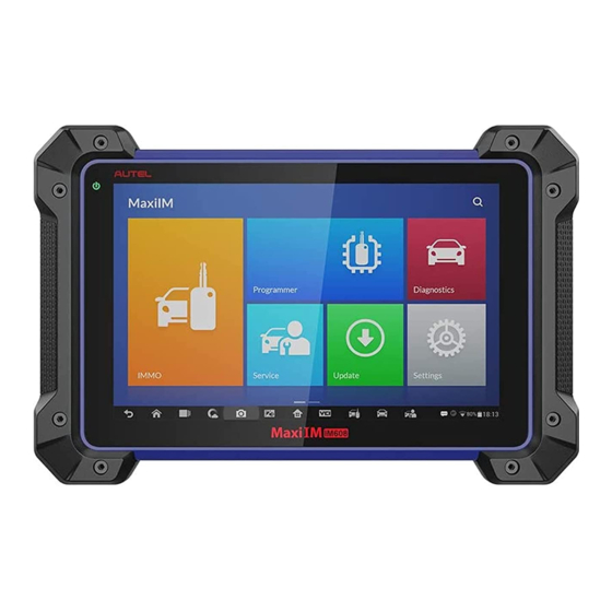
General Introduction Autel presents the MaxiIM IM608 Pro as the most advanced and smart key programming tool that combines the most powerful IMMO and programming functions with OE-level diagnostics and advanced service functions in one Android based 10.1-inch touchscreen tablet. - Page 10 Ambient Light Sensor – detects ambient brightness. Power LED – indicates battery level & charging or system status. Microphone The power LED displays green, yellow or red depending on power level and operating state. A. Green Illuminates green when the Display Tablet is charging and the battery level is above 90%.
- Page 11 Loudspeaker Camera Lens Camera Flash Figure 2-3 Display Tablet Top View 10. DC Power Supply Input Port 11. Headphone Jack 12. USB Port 13. HDMI (high-definition multimedia interface) Port 14. USB Port 15. Mini USB Port 16. Lock/Power Button – turns the device on & off with long press, or locks the screen with short press.
- Page 12 External Power Supply The Display Tablet can be powered from a wall socket using the AC/DC power adapter. The AC/DC power supply also charges the internal battery pack. Technical Specifications Table 2-1 Specifications Item Description Operating System Android 4.4.2, KitKat Samsung Exynos hexa-core Processor (1.3GHz Processor Quad-core ARM Cortex-A7 + 1.7GHz Dual-core...
-
Page 13: Maxiflash - Wireless Diagnostic Interface
Item Description Power 6.5 W Consumption Operating Temp. 0 to 50° C (32 to 122° F) Storage Temp. -20 to 60° C (-4 to 140° F) Dimensions ( 300 mm (11.81”) x 220 mm (8.66”) x 50 mm (1.97”) WxHxD Weight NW: 1.42 kg (3.13 lb.) GW: 8.655 kg (19.08 lb.) - Page 14 Functional Description Figure 2-4 MaxiFlash Views Power Port – connects the device and the power source with the adapter. Vehicle Connector – connects the device to the vehicle’s DLC via a standard high density DB-26 MVCI – OBDII cable. USB Port Vehicle LED Connection LED Power LED...
- Page 15 Color Description Illuminates solid green when properly Green connected with the display tablet via the USB cable. Connection Illuminates solid blue when connected with the Blue display tablet via wireless (BT) connection. Illuminates solid green when powered on. Green Flashes red when system failure occurs. power illuminates amber...
-
Page 16: Xp400 Pro
Name Value Weight 0.29kg (0.64lb) XP400 Pro The XP400 Pro has the following functions: (1) Read transponder data (including Mercedes Benz infrared smart key), and generate exclusive keys. (2) Read/write on-board EEPROM chip data, and read/write MCU/ECU chip data. (3) Read/write remote control transponder data and detect key frequency. Compatible with the key Programming diagnostic tablet or a computer with installed key Programming software, the XP400 Pro can read/write transponder data quickly and accurately. - Page 17 USB Port – provides data communication and 5V DC power supply. DC Port – provides 12V DC power supply. DB 26-Pin Port – connects with the Mercedes Benz infrared collector, ECU cable, MCU cable and MC9S12 cable. Cross Signal Pins – holds the MCU spare cable or DIY signal interface. Vehicle Key Slot –...
- Page 18 Color Definition Note Blue CANH Brown BOOTM Yellow White Table 2-5 Definitions of MCU Cable Color Definition Note Red and White VPP1 Red and Black VPP2 Red and Yellow +12V Red and Blue VPPR Black Green and White White Brown Gray Blue Orange...
- Page 19 Color Definition Note Shielded Black Twisted Shielded White Twisted Table 2-6 Definitions of MC9S12 Cable Color Definition Note Black Green XCLKS Blue Yellow RESET Shielded Black Twisted Shielded White Twisted Cross-shaped Signal Pin The Cross-shaped signal pin is used to place MCU spare cable or DIY signal cable to read or write MCU and ECU chips.
- Page 20 Mercedes Infrared Slot Holds Mercedes vehicle key to read or write Mercedes vehicle key information. Status Indicator The Status Indicator shows the current operating status of the XP400 Pro. Table 2-7 Description of the Status Indicator Indicator Status Description Light Green Powered on and default Flash Green Communication...
- Page 21 Manufacturer Chip Model Note AT25XXX AT26XXX AT34XXX AT45DXX AT59CXX AT93CXX CAT10XX CAT24XXX CAT25XXX CAT35CXXX CATALYST/ONSEMI CAT59CXX CAT64LCXX CAT93CXX PM25LDXXX PM25LVXXX CHINGIS/PMC PM25WXXX EN25BXX EN25DXXX EN25FXX EN25MXX EN25QXXX...
- Page 22 Manufacturer Chip Model Note EN25TXX ESMT F25L0XX XL[S]24CXX XL[S]93CXX EXEL XL[S]93LCXX PM24CXXX PM24CLXXX PM25XXX FM93CXX FM93CSXX FAIRCHILD/NSC/RAMTRON NM24CXX NM34XXX NM93XX NM93CXX NM93CSXX FUJITSU MB85RCXX BAWXXXXXX ER59XXX GIGADEVICE GD25QXX GRUNDIG GRX-XXX HOLTEK HT93CXX...
- Page 23 Manufacturer Chip Model Note NVMXXXX MDAXXXX KHIC KH25LXXXX MACRONIX MX25LXX 24AAXX 24[F][L]CXX 25AAXXX 25LCXXX MICROCHIP 93C/AA/LCXX[A] 93C/AA/LCXX[B] 93C/AA/LCXX[C] M25PXXX MICRON M25QXXX MITSUBISHI M6M800X1 UPD625X M25PXXX NUMONYX M25QXXX MSM16XXX PCT25VF032B PHILIPS PCA85XX PIONEER PDXXXX...
- Page 24 Manufacturer Chip Model Note BR24CXX BR90XX ROHM BR93XXX KM93CXX SAMSUNG KS24XXXX S-24XXX SEIKO S-93XXX SONY CXK10XX S25FLXX SPANSION S99-50084 SST25LF0X0A SST25VFXXX M24CXX M25P[E/X]XX M34XXX M35XXX M8571 M93C/SXX M95XXX ST24XXX ST25XXX...
- Page 25 Manufacturer Chip Model Note ST93C/CSX6/X7 ST950XX ST95P0X W25PXXX WINBOND W25XXXX X24XXX XICOR X504X MCU Coverage Table 2-9 MCU Coverage Manufacturer Chip Model Note ATTINYXXX AT90XXXXX AT90S2313 AT90S8515 AT90CAN32 ATMEL AT90CAN64 AT90CAN128 ATMEGA48XX 48/48P/48PB ATMEGA8 ATMEGA88XX 88/88P/88PB...
- Page 26 Manufacturer Chip Model Note ATMEGA16XX 16/162/163/164(P)/165( P)/168(P/PB)/169(P) ATMEGA32XX 32/323/324(P/PB)/325( P)/328(P/PB)/329(P)/32 90(P) ATMEGA33XX 00/00P ATMEGA64XX 64/644(P)/645(P)/6450( P)/649(P)/6490(P) ATMEGA103 ATMEGA128X 128/1280/1281/1284(P) ATMEGA256X 60/61 ATMEGA8515 ATMEGA8535 MC68HC05B4 MC68HC05B6 MC68HC05B8 MC68HC05B16 MC68HC05B32 FREESCALE MC68HC05H12 MC68HC05L28 MC68HC05P3 MC68HC05X16...
- Page 27 Manufacturer Chip Model Note MC68HC05X32 MC68HC705B16 MC68HC705B16N MC68HC705B32 MC68HC705D9 MC68HC705E6 MC68HC705E6 MC68HC705P3 MC68HC705X32 MC68HC11A1 MC68HC11A8 MC68HC11E1 MC68HC11E9 MC68HC11E20 MC68HC11E32 MC68HC11EA9 MC68HC11F1 MC68HC11K4 MC68HC11KA2 MC68HC11KA4 MC68HC11KG4...
- Page 28 Manufacturer Chip Model Note MC68HC11KS2 MC68HC11KW1 MC68HC11L6 MC68HC11P2 MC68HC11PA8 MC68HC11PH8 MC68HC711E9 MC68HC711E20 MC68HC711EA9 MC68HC711PH8 MC68HC08ASxxA MC68HC08ASxxA MC68HC908AB32 MC68HC908APxxA MC68HC908AP64 MC68HC908AZxx MC68HC908AZxxA MC68HC908GP32 MC68HC908GRxx MC68HC908GTxx MC68HC908GZxx...
- Page 29 Manufacturer Chip Model Note MC68HC908JB8 MC68HC908JB16 MC68HC908JK3 MC68HC908JL3 MC68HC908JL16 MC68HC908KX2 MC68HC908LJxx MC68HC908LKxx MC68HC908QC4 MC68HC908QC8 MC68HC908QC16 MC68HC908QY2 MC68HC912D60 MC68HC912D60A MC68HC912D60C MC68HC912D60P MC68HC912DG128 MC68HC912DG128A MC68HC912DG128C MC68HC912DG128P MC68HC912DJ128A...
- Page 30 Manufacturer Chip Model Note MC68HC912DT128 MC68HC912DT128A MC68HC912DT128C MC68HC912DT128P MC9RS08KA1 MC9RS08KA2 MC9RS08LA8 MC9S08AC8 MC9S08AC16 MC9S08AC32 MC9S08AC48 MC9S08AC60 MC9S08AC96 MC9S08AC128 MC9S08AW8 MC9S08AW16 MC9S08AW32 MC9S08AW48 MC9S08AW60 MC9S08DV16 MC9S08DV32...
- Page 31 Manufacturer Chip Model Note MC9S08DV48 MC9S08DV60 MC9S08DV96 MC9S08DV128 MC9S08DN16 MC9S08DN32 MC9S08DN48 MC9S08DN60 MC9S08DZ16 MC9S08DZ32 MC9S08DZ48 MC9S08DZ60 MC9S08DZ96 MC9S08DZ128 MC9S08EL16 MC9S08EL32 MC9S08FL8 MC9S08FL16 MC9S08GB32 MC9S08GB60 MC9S08GT16...
- Page 32 Manufacturer Chip Model Note MC9S08GT32 MC9S08GT60 MC9S08JM8 MC9S08JM16 MC9S08JM32 MC9S08JM60 MC9S08JS8 MC9S08JS16 MC9S08LC36 MC9S08LC60 MC9S08LG16 MC9S08LG32 MC9S08LH36 MC9S08LH64 MC9S08LL8 MC9S08LL16 MC9S08LL36 MC9S08LL64 MC9S08MM32 MC9S08MM32A MC9S08MM64...
- Page 33 Manufacturer Chip Model Note MC9S08MP12 MC9S08MP16 MC9S08QA2 MC9S08QA4 MC9S08QB4 MC9S08QB8 MC9S08QD2 MC9S08QD4 MC9S08QE4 MC9S08QE8 MC9S08QE16 MC9S08QE32 MC9S08QE64 MC9S08QE96 MC9S08QE128 MC9S08QG4 MC9S08QG8 MC9S08RC8 MC9S08RC16 MC9S08RC32 MC9S08RC60...
- Page 34 Manufacturer Chip Model Note MC9S08RD8 MC9S08RD16 MC9S08RD32 MC9S08RD60 MC9S08RE8 MC9S08RE16 MC9S08RE32 MC9S08RE60 MC9S08RG32 MC9S08RG60 MC9S08SC4 MC9S08SE4 MC9S08SE8 MC9S08SF4 MC9S08SG4 MC9S08SG8 MC9S08SG16 MC9S08SG32 MC9S08SH4 MC9S08SH8 MC9S08SL8...
- Page 35 Manufacturer Chip Model Note MC9S08SL16 MC9S08SU8 MC9S08SU16 MC9S08SV8 MC9S08SV16 MC9S12A32 MC9S12A64 MC9S12A128 MC9S12A256 MC9S12A512 MC9S12B64 MC9S12B128 MC9S12B256 MC9S12C32 MC9S12C64 MC9S12C96 MC9S12C128 MC9S12D32 MC9S12D64 MC9S12DB128 MC9S12DG128...
- Page 36 Manufacturer Chip Model Note MC9S12DG256 MC9S12DJ64 MC9S12DJ128 MC9S12DJ256 MC9S12DJ512 MC9S12DP256 MC9S12DP512 MC9S12DT128 MC9S12DT256 MC9S12DT512 MC9S12GC16 MC9S12GC32 MC9S12GC64 MC9S12GC96 MC9S12GC128 MC9S12KG32 MC9S12KG64 MC9S12KG128 MC9S12KG256 MC9S12KT128 MC9S12KT256...
- Page 37 Manufacturer Chip Model Note MC9S12KL64 MC9S12KL128 MC9S12H128 MC9S12H256 MC9S12HN64 MC9S12HA32 MC9S12HA48 MC9S12HA64 MC9S12HY32 MC9S12HY48 MC9S12HY64 MC9S12HZ64 MC9S12HZ128 MC9S12HZ256 MC9S12P32 MC9S12P64 MC9S12P96 MC9S12P128 MC9S12XA128 MC9S12XA256 MC9S12XA512...
- Page 38 Manufacturer Chip Model Note MC9S12XB128 MC9S12XB256 MC9S12XD64 MC9S12XD128 MC9S12XD256 MC9S12XDG128 MC9S12XDG256 MC9S12XDG512 MC9S12XDP512 MC9S12XDQ256 MC9S12XDT256 MC9S12XDT384 MC9S12XDT512 MC9S12XEA128 MC9S12XEA256 MC9S12XEG128 MC9S12XEG256 MC9S12XEG384 MC9S12XEP768 MC9S12XEP100 MC9S12XEQ384...
- Page 39 Manufacturer Chip Model Note MC9S12XEQ512 MC9S12XES384 MC9S12XET256 MC9S12XET512 MC9S12XF128 MC9S12XF256 MC9S12XF384 MC9S12XF512 MC9S12XHY128 MC9S12XHY256 MC9S12XHZ256 MC9S12XHZ384 MC9S12XHZ512 MC9S12XS64 MC9S12XS128 MC9S12XS256 MPC5601D MPC5602B MPC5602D MPC5603B MPC5603C...
- Page 40 Manufacturer Chip Model Note MPC5604B MPC5604C MPC5605B MPC5606B MPC5607B MPC5601P MPC5602P MPC5603P MPC5604P MPC5604E MPC5602S MPC5604S MPC5606S MB90F038S MB90F342 MB90F345 MB90F346 FUJITSU MB90F347 MB90F349 MB90F352 MB90F357...
- Page 41 Manufacturer Chip Model Note MB90F387 MB90F423 MB90F428 MB90F438L MB90F439 MB90F455 MB90F456 MB90F457 MB90F462 MB90F497 MB90F498G MB90F523B MB90F543 MB90F546 MB90F548 MB90F549 MB90F553A MB90F594A MB90F654A MB90F867 MB95F108AM...
- Page 42 Manufacturer Chip Model Note MB95F108B MB95F116MA MB95F118B MB95F118M MB95F128 MB95F128MB MB95F136MB MB95F156M MB95F166 MB95F168MA MB96F348 MB96F385 MB96F386 MB96F387 MB96F673 MB96F675 MB96F683 MB96F685 MB96F693 MB96F695 MB96F696...
- Page 43 Manufacturer Chip Model Note MB96F6A5 MB96F6A6 XC164CS-16F XC164CS-32F XC2060M-104F XC2060N-40F XC2080-96F XC2336A-56F XC2336A-72F XC2361A-56F XC2361A-72F XC2363A-56F INFINEON XC2363A-72F XC2364A-56F XC2364A-72F XC2364A-104F XC2365A-56F XC2365A-72F XC2365A-104F XC2336B-24F XC2336B-40F...
- Page 44 Manufacturer Chip Model Note XC2361B-24F XC2361B-40F XC2363B-24F XC2363B-40F XC2364B-24F XC2364B-40F XC2365B-24F XC2365B-40F XC2765X-72F XC2765X-104F PIC12F508 PIC12F509 PIC12F510 PIC12F609 PIC12F615 PIC12F617 MICROCHIP PIC12F629 PIC12F635 PIC12F675 PIC12F683 PIC12F752...
- Page 45 Manufacturer Chip Model Note PIC12(L)F1501 PIC12(L)F1552 PIC12(L)F1571 PIC12(L)F1572 PIC12(L)F1612 PIC12(L)F1822 PIC12(L)F1840 PIC12HV609 PIC12HV615 PIC16F505 PIC16F506 PIC16F54 PIC16F610 PIC16F616 PIC16F631 PIC16F636 PIC16F639 PIC16F677 PIC16F684 PIC16F685 PIC16F687...
- Page 46 Manufacturer Chip Model Note PIC16F688 PIC16F689 PIC16F690 PIC16F707 PIC16F72 PIC16F722 PIC16F723 PIC16F724 PIC16F726 PIC16F727 PIC16F73 PIC16F74 PIC16F76 PIC16F77 PIC16F818 PIC16F819 PIC16F83 PIC16F84 PIC16F87 PIC16F870 PIC16F871...
- Page 47 Manufacturer Chip Model Note PIC16F872 PIC16F873 PIC16F874 PIC16F876 PIC16F877 PIC16F88 PIC16F882 PIC16F883 PIC16F884 PIC16F886 PIC16F887 PIC16F913 PIC16F914 PIC16F916 PIC16F917 PIC16F946 PIC16F1454 PIC16F1455 PIC16F1459 PIC16(L)F707 PIC16(L)F722...
- Page 48 Manufacturer Chip Model Note PIC16(L)F723 PIC16(L)F724 PIC16(L)F726 PIC16(L)F727 PIC16(L)F88 PIC16(L)F1454 PIC16(L)F1455 PIC16(L)F1459 PIC16(L)F1503 PIC16(L)F1507 PIC16(L)F1508 PIC16(L)F1509 PIC16(L)F1512 PIC16(L)F1513 PIC16(L)F1516 PIC16(L)F1517 PIC16(L)F1518 PIC16(L)F1519 PIC16(L)F1526 PIC16(L)F1527 PIC16(L)F1554...
- Page 49 Manufacturer Chip Model Note PIC16(L)F1559 PIC16(L)F1566 PIC16(L)F1567 PIC16(L)F1613 PIC16(L)F1614 PIC16(L)F1615 PIC16(L)F1618 PIC16(L)F1619 PIC16(L)F1703 PIC16(L)F1704 PIC16(L)F1705 PIC16(L)F1707 PIC16(L)F1708 PIC16(L)F1709 PIC16(L)F1713 PIC16(L)F1716 PIC16(L)F1717 PIC16(L)F1718 PIC16(L)F1719 PIC16(L)F1823 PIC16(L)F1824...
- Page 50 Manufacturer Chip Model Note PIC16(L)F1825 PIC16(L)F1826 PIC16(L)F1827 PIC16(L)F1828 PIC16(L)F1829 PIC16(L)F18313 PIC16(L)F18323 PIC16(L)F18324 PIC16(L)F18325 PIC16(L)F18326 PIC16(L)F18344 PIC16(L)F18345 PIC16(L)F18346 PIC16(L)F1847 PIC16(L)F1902 PIC16(L)F1903 PIC16(L)F1904 PIC16(L)F1906 PIC16(L)F1907 PIC16(L)F1933 PIC16(L)F1934...
- Page 51 Manufacturer Chip Model Note PIC16(L)F1936 PIC16(L)F1937 PIC16(L)F1938 PIC16(L)F1939 PIC16(L)F1946 PIC16(L)F1947 PIC16HV610 PIC16HV616 PIC18F242 PIC18F248 PIC18F252 PIC18F258 PIC18F442 PIC18F448 PIC18F452 PIC18F458 PIC18F1220 PIC18F1230 PIC18F1320 PIC18F1330 PIC18F2220...
- Page 52 Manufacturer Chip Model Note PIC18F2221 PIC18F2320 PIC18F2321 PIC18F2410 PIC18F2420 PIC18F2423 PIC18F2450 PIC18F2455 PIC18F2458 PIC18F2480 PIC18F2510 PIC18F2515 PIC18F2520 PIC18F2523 PIC18F2525 PIC18F2550 PIC18F2553 PIC18F2580 PIC18F2585 PIC18F2610 PIC18F2620...
- Page 53 Manufacturer Chip Model Note PIC18F2680 PIC18F2682 PIC18F2685 PIC18F4220 PIC18F4221 PIC18F4320 PIC18F4321 PIC18F4410 PIC18F4420 PIC18F4423 PIC18F4450 PIC18F4455 PIC18F4458 PIC18F4480 PIC18F4510 PIC18F4515 PIC18F4520 PIC18F4523 PIC18F4525 PIC18F4550 PIC18F4553...
- Page 54 Manufacturer Chip Model Note PIC18F4580 PIC18F4585 PIC18F4610 PIC18F4620 PIC18F4680 PIC18F4682 PIC18F4685 PIC18F6527 PIC18F6622 PIC18F6627 PIC18F6628 PIC18F6722 PIC18F6723 PIC18F8527 PIC18F8622 PIC18F8627 PIC18F8628 PIC18F8722 PIC18F8723 PIC18F23K20 PIC18F24K20...
- Page 55 Manufacturer Chip Model Note PIC18F25K20 PIC18F26K20 PIC18F43K20 PIC18F44K20 PIC18F45K20 PIC18F46K20 PIC18(L)F13K22 PIC18(L)F13K50 PIC18(L)F14K22 PIC18(L)F14K50 PIC18(L)F24K50 PIC18(L)F25K50 PIC18(L)F26K50 PIC18(L)F45K50 PIC18(L)F46K50 PIC18(L)F24J10 PIC18(L)F24J11 PIC18(L)F24J50 PIC18(L)F25J10 PIC18(L)F25J11 PIC18(L)F25J50...
- Page 56 Manufacturer Chip Model Note PIC18(L)F26J11 PIC18(L)F26J13 PIC18(L)F26J50 PIC18(L)F26J53 PIC18(L)F27J13 PIC18(L)F27J53 PIC18(L)F44J10 PIC18(L)F44J11 PIC18(L)F44J50 PIC18(L)F45J10 PIC18(L)F45J11 PIC18(L)F45J50 PIC18(L)F46J11 PIC18(L)F46J13 PIC18(L)F46J50 PIC18(L)F46J53 PIC18(L)F47J13 PIC18(L)F47J53 PIC24F08KA101 PIC24F08KA102 PIC24F16KA101...
- Page 57 Manufacturer Chip Model Note PIC24F16KA102 CR16MCS9 CR16MCT9 R5F21112 R5F21113 R5F21114 R5F21122 R5F21123 R5F21124 R5F21244 R5F21245 R5F21246 RENESAS R5F21247 R5F21248 R5F21254 R5F21255 R5F21256 R5F21257 R5F21258 R5F21262 R5F21264...
- Page 58 Manufacturer Chip Model Note R5F21265 R5F21266 R5F21272 R5F21274 R5F21275 R5F21276 R5F212A7 R5F212A8 R5F212AA R5F212AC R5F212B7 R5F212B8 R5F212BA R5F212BC R5F212C7 R5F212C8 R5F212CA R5F212CC R5F212D7 R5F212D8 R5F212DA...
- Page 59 Manufacturer Chip Model Note R5F212DC R5F21354 R5F21355 R5F21356 R5F21357 R5F21358 R5F2135A R5F2135C R5F21546E R5F21547E R5F21548E R5F2154AE R5F2154CE R5F21546F R5F21547F R5F21548F R5F2154AF R5F2154CF R5F21546G R5F21547G R5F21548G...
- Page 60 Manufacturer Chip Model Note R5F2154AG R5F2154CG R5F21546H R5F21547H R5F21548H R5F2154AH R5F2154CH R5F363A6 R5F363AE R5F363AK R5F363AM R5F363B6 R5F363BE R5F36406 R5F3640E R5F3640K R5F3640M R5F364A6 R5F364AE R5F364AM R5F36506...
- Page 61 Manufacturer Chip Model Note R5F3650E R5F3650K R5F3650M R5F3650N R5F36CA6 R5F36CAE R5F36CAK R5F36CAM R5F64110 R5F64111 R5F64112 R5F64114 R5F64115 R5F64116 R5F6411E R5F6411F R5F64165 R5F64166 R5F64167 R5F64168 R5F64169...
- Page 62 Manufacturer Chip Model Note R5F64175 R5F64176 R5F64177 R5F64178 R5F64179 R5F6417A R5F6417B R5F64185 R5F64186 R5F64187 R5F64188 R5F64189 R5F64206 R5F64207 R5F6420A R5F6420B R5F64210 R5F64211 R5F64212 R5F64213 R5F64216...
- Page 63 Manufacturer Chip Model Note R5F64217 R5F64218 R5F64219 R5F6421A R5F6421B R5F6421C R5F6421D R5F6421E R5F6421F R5F6421G R5F6421H R5F6442F R5F6442H R5F6445F R5F6445H R5F64116J R5F64116K R5F64116L R5F64116M R5F64117J R5F64117K...
- Page 64 Manufacturer Chip Model Note R5F64117L R5F64117M R5F64118J R5F64118K R5F64118L R5F64118M R5F64524JFD R5F64524LFD R5F64524KFD R5F64525JFD R5F64525LFD R5F64525KFD R5F6452MJFD R5F6452MLFD R5F6452MKFD R5F6452NJFD R5F6452NLFD R5F6452NKFD M30620FC M30624FG M30873FH...
- Page 65 Manufacturer Chip Model Note M30875FH M30876FJ M30878FJ M30879FK M30879FL M3087BFK M3087BFL M30880FW M30880FH M30880FJ M30882FW M30882FH M30882FJ R7F701002 R7F701003 R7F701006 R7F701007 R7F701008 R7F701009 R7F701010 R7F701011...
- Page 66 Manufacturer Chip Model Note R7F701012 R7F701013 R7F701014 R7F701015 R7F701016 R7F701017 R7F701018 R7F701019 R7F701020 R7F701021 R7F701022 R7F701023 R7F701024 R7F701025 R7F701028 R7F701029 R7F701030 R7F701032 R7F701033 R7F701034 R7F701040...
- Page 67 Manufacturer Chip Model Note R7F701041 R7F701042 R7F701043 R7F701044 R7F701045 R7F701046 R7F701047 R7F701048 R7F701049 R7F701050 R7F701051 R7F701052 R7F701053 R7F701054 R7F701055 R7F701056 R7F701057 R7F701A03 R7F701A23 R7F701542 R7F701543...
- Page 68 Manufacturer Chip Model Note R7F701546 R7F701547 R7F701557 R7F701560 R7F701561 R7F701562 R7F701563 R7F701566 R7F701567 R7F701577 R7F701580 R7F701581 R7F701582 R7F701583 R7F701586 R7F701587 R7F701597 R7F701602 R7F701603 R7F701610 R7F701611...
- Page 69 Manufacturer Chip Model Note R7F701612 R7F701613 R7F701620 R7F701621 R7F701622 R7F701623 uPD70F3230 uPD70F3231 uPD70F3232 uPD70F3233 uPD70F3234 uPD70F3235 uPD70F3236 uPD70F3237 uPD70F3238 uPD70F3239 uPD70F3333 uPD70F3334 uPD70F3335 uPD70F3336 uPD70F3340...
- Page 70 Manufacturer Chip Model Note uPD70F3341 uPD70F3342 uPD70F3343 uPD70F3344 uPD70F3345 uPD70F3346 uPD70F3347 uPD70F3348 uPD70F3349 uPD70F3350 uPD70F3351 uPD70F3352 uPD70F3353 uPD70F3354 uPD70F3355 uPD70F3356 uPD70F3357 uPD70F3358 uPD70F3364 uPD70F3365 uPD70F3366...
- Page 71 Manufacturer Chip Model Note uPD70F3367 uPD70F3368 uPD70F3370A uPD70F3371 uPD70F3372 uPD70F3373 uPD70F3374 uPD70F3375 uPD70F3376A uPD70F3377A uPD70F3378 uPD70F3379 uPD70F3380 uPD70F3381 uPD70F3382 uPD70F3383 uPD70F3384 uPD70F3385 uPD70F3402 uPD70F3403 uPD70F3403A...
- Page 72 Manufacturer Chip Model Note uPD70F3421 uPD70F3422 uPD70F3423 uPD70F3424 uPD70F3425 uPD70F3426 uPD70F3427 uPD70F3433 uPD70F3438 uPD70F3451 uPD70F3452 uPD70F3453 uPD70F3454 uPD70F3461 uPD70F3464 uPD70F3465 uPD70F3466 uPD70F3469 uPD70F3470 uPD70F3471 uPD70F3472...
- Page 73 Manufacturer Chip Model Note uPD70F3474 uPD70F3475 uPD70F3476 uPD70F3477 uPD70F3478 uPD70F3479 uPD70F3480 uPD70F3481 uPD70F3482 uPD70F3483 uPD70F3486 uPD70F3487 uPD70F3488 uPD70F3505A uPD70F3506 uPD70F3507 uPD70F3508 uPD70F3509 uPD70F3522 uPD70F3523 uPD70F3524...
- Page 74 Manufacturer Chip Model Note uPD70F3525 uPD70F3526 uPD70F3529 uPD70F3548 uPD70F3549 uPD70F3550 uPD70F3551 uPD70F3552 uPD70F3553 uPD70F3554 uPD70F3555 uPD70F3556 uPD70F3557 uPD70F3558 uPD70F3559 uPD70F3560 uPD70F3561 uPD70F3570 uPD70F3571 uPD70F3572 uPD70F3573...
- Page 75 Manufacturer Chip Model Note uPD70F3574 uPD70F3575 uPD70F3576 uPD70F3577 uPD70F3578 uPD70F3579 uPD70F3580 uPD70F3582 uPD70F3583 uPD70F3584 uPD70F3585 uPD70F3592 uPD70F3610 uPD70F3611 uPD70F3612 uPD70F3613 uPD70F3614 uPD70F3615 uPD70F3616 uPD70F3617 uPD70F3618...
- Page 76 Manufacturer Chip Model Note uPD70F3619 uPD70F3620 uPD70F3621 uPD70F3622 uPD70F3623 uPD70F3624 uPD70F3625 uPD70F3626 uPD70F3627 uPD70F3628 uPD70F3629 uPD70F3630 uPD70F3631 uPD70F3632 uPD70F3633 uPD70F3634 uPD70F3635 uPD70F3636 uPD70F3637 uPD70F3638 uPD70F3700...
- Page 77 Manufacturer Chip Model Note uPD70F3701 uPD70F3702 uPD70F3703 uPD70F3704 uPD70F3706 uPD70F3707 uPD70F3709 uPD70F3710 uPD70F3711 uPD70F3712 uPD70F3715 uPD70F3716 uPD70F3717 uPD70F3718 uPD70F3719 uPD70F3720 uPD70F3721 uPD70F3722 uPD70F3723 uPD70F3724 uPD70F3739...
- Page 78 Manufacturer Chip Model Note uPD70F3740 uPD70F3741 uPD70F3742 uPD70F3743 uPD70F3744 uPD70F3745 uPD70F3746 uPD70F3747 uPD70F3750 uPD70F3752 uPD70F3755 uPD70F3757 uPD70F3778 uPD70F3779 uPD70F3780 uPD70F3781 uPD70F3782 uPD70F3783 uPD70F3784 uPD70F3785 uPD70F3786...
- Page 79 Manufacturer Chip Model Note uPD70F3809 uPD70F3810 uPD70F3811 uPD70F3812 uPD70F3813 uPD70F3814 uPD70F3815 uPD70F3816 uPD70F3817 uPD70F3818 uPD70F3819 uPD70F3820 uPD70F3821 uPD70F3822 uPD70F3823 uPD70F3824 uPD70F3825 uPD70F3826 uPD70F3827 uPD70F3828 uPD70F3829...
- Page 80 Manufacturer Chip Model Note uPD70F3830 uPD70F3831 uPD70F3832 uPD70F3833 uPD70F3834 uPD70F3835 uPD70F3836 uPD70F3837 uPD70F3925 uPD70F3926 uPD70F3927 uPD70F3931 uPD70F3932 uPD70F3933 uPD70F3934 uPD70F3935 uPD70F3936 uPD70F3937 uPD70F3938 uPD70F3939 uPD70F4000...
- Page 81 Manufacturer Chip Model Note uPD70F4001 uPD70F4002 uPD70F4003 uPD70F4004 uPD70F4005 uPD70F4006 uPD70F4007 uPD70F4008 uPD70F4009 uPD70F4010 uPD70F4011 uPD70F4012 uPD70F4177 uPD70F4178 uPD70F4179 uPD70F4180 uPD76F0117 uPD76F0192 SAMSUNG S3F9488 SILABS C8051FXXX SPC5607B...
- Page 82 Manufacturer Chip Model Note SPC560BXX SPC560CXX SPC560DXX SPC560PXX SPC560APXX ST10F2XX STM8AF5XXX STM8AF6XXX STM8AL31XX STM8AL3LXX STM8L051XX STM8L052XX STM8L101XX STM8L151XX STM8L152XX STM8L162XX STM8S003XX STM8S005XX STM8S007XX STM8S103XX STM8S105XX...
- Page 83 Manufacturer Chip Model Note STM8S207XX STM8S208XX STM8S903XX STM32F030XXX STM32F031XXX STM32F050XXX STM32F051XXX STM32F100XXX STM32F101XXX STM32F103XXX STM32F205RXX MSP430F1XX2 MSP430F123 MSP430F13X MSP430F14XX MSP430F15XX MSP430F16XX MSP430F20XX MSP430F21XX MSP430F22XX MSP430F23X...
-
Page 84: Accessories Kit
Manufacturer Chip Model Note MSP430F24XX MSP430F4XX Technical Specifications Table 2-10 Specifications Item Description Operating Temperature -10℃ ~ 70℃ (14℉ ~ 158℉) Storage Temperature -20℃ ~ 85℃ (-4℉ ~ 185℉) Port Type B-USB, DB26, DC12 Input Voltage 5 VDC, 12VDC Operating Current <... - Page 85 Figure 2-6 Main Cable Other Included Accessories USB Cable Mini USB Cable Connects the Display Tablet to the PC. AC/DC Adapter (12V) Light Fuse 6*30mm (2pcs) Cigarette Lighter AAC001 MED17 Cable APC101 (USB Cable) APB129 EEPROM Adapter APB125 Mercedes Infrared Collector APB103 MCU_PLCC52...
- Page 86 APB104 MCU_FQFP64 APB105 MCU_FQFP80 APB106 MCU_FQFP112 APB107 MCU_FQFP114 APB108 MCU_FQFP176 APB109 MCU_FQFP32 APB110 MCU_FQFP48 APB111 MCU_SO28 APA002 EEPROM Socket...
- Page 87 APA101 Signal Cable APA103 EEPROM Clamp APA107 ECU Cable APA108 MCU Cable APA109 MC9S12 Cable Connect Cable Quick Guide Device connection and software update instructions. APB113 PCF79XX Adapter (Optional) APB114 EWS3 Adapter (Optional) APB115 NEC Adapter Plate (Optional) APB118 NEC Steering Lock Adapter (Optional)
- Page 88 APB119 TB28FXXX Adapter (Optional) APB120 TMS370 Adapter (Optional) APB121 AM29FXXX Adapter Plate (Optional) APB122 AM29FXXX Adapter 1 (Optional) APB123 AM29FXXX Adapter 2 (Optional) APB126 M35080&D80 Adapter (Optional) APB127 MC68HC(7)05BXX Adapter (Optional) APB128 MC68HC05X32 Adapter (Optional) NOTE Optional Accessories can be purchased separately.
-
Page 89: Getting Started
Getting Started Ensure the tablet is sufficiently charged or is connected to the external power supply (see Power Sources on page 5). NOTE The images and illustrations depicted in this manual may differ from the actual ones. Powering Up Long press the Lock/Power button on the top right of the tablet to power on the unit. - Page 90 NOTE The tablet screen is locked by default when first powered on. It is recommended to lock the screen to protect the information in the system and reduce the power consumption. The touch screen navigation is menu driven enabling quick access to functions and features by tapping on options headings and answering dialog windows.
- Page 91 Button Name Description Accesses the organization system for saved Data Manager data files. See Data Manager on page 171 for details. Accesses Shop manager database to store workshop, customer information and vehicle Shop Manager test history. See Shop Manager on page 176 for details.
- Page 92 Button Name Description Brightness/ Adjust the brightness and volume of the tool. Volume MaxiIM Returns to MaxiIM Job Menu. Home Returns to VCI Manager screen. IMMO Returns to the IMMO screen. Shortcut Diagnostic Returns to the Diagnostic screen. Shortcut Service Returns to the Service screen.
-
Page 93: Powering Down
Button Name Description Enables/disables Airplane Mode when Airplane Mode pressed. Launches the Android System Settings System Settings screen when pressed. Powering Down All vehicle communications must be terminated before shutting down the Display Tablet. A warning message displays if you attempt to shut down the Display Tablet when it is communicating with the vehicle. -
Page 94: Immo
Remote Control Learning, Remote Control Add, etc. Establish Vehicle Communication The IMMO operations require connecting the MaxiIM IM608 tablet to the test vehicle through the MaxiFlash using the main cable and the included USB cable (2m). To establish proper vehicle communication to the tablet, you need to perform the following steps: Connect the MaxiFlash to the vehicle’s DLC for both communication and... - Page 95 OBD II Vehicle Connection This type of connection only requires the main cable without any additional adapter. To connect to an OBD II vehicle Connect the main cable’s female adapter to the Vehicle Data Connector on the MaxiFlash, and tighten the captive screws. Connect the cable’s 16-pin male adapter to the vehicle’s DLC, which is generally located under the vehicle dashboard.
- Page 96 To connect the cigarette lighter Plug the DC power connector of the cigarette lighter into the DC power supply input port on the device. Connect the male connector of the cigarette lighter into the vehicle’s cigarette lighter receptacle. NOTE After the MaxiFlash is successfully connected to the vehicle, the Power LED on the device illuminates, and a brief beep sound will be heard.
- Page 97 automatically starts scanning for available VCI devices around for BT pairing. The found devices are listed in the Setting section on the right side of the screen. NOTE If no VCI device is found, this may indicate that the signal strength of the transmitter is too weak to be detected.
- Page 98 Autel or local distributor for technical support.
-
Page 99: Getting Started
Getting Started Ensure a communication link is established between the test vehicle and the tablet via the main cable, and the XP400 Pro is connected to the tablet with the supplied USB cable. Vehicle Menu Layout When the tablet is properly connected to the vehicle, the platform is ready to start vehicle diagnosis. -
Page 100: Vehicle Identification
Displays a dropdown list; tap Auto Detect for auto VIN detection; tap Manual Input to enter VIN Scan manually. Displays all the vehicle makes in the vehicle menu. Displays the stored test vehicle history records. This option provides you direct access to the previously History tested vehicle recorded during previous test sessions. - Page 101 except Auto VIN Scan and Manual VIN Input methods, technicians can also manually select vehicle manufacturer, instrument information step by step to locate the desired IMMO part, but it is a little different from Automatic Selection and Manual Selection. Besides, as Programming does not require connection with the vehicle, therefore, Auto VIN Scan is not applicable for this application, and technicians can manually select the part information follow the onscreen instructions to display the function menu.
- Page 102 to confirm the vehicle profile. If the VIN does not match with the test vehicle’s VIN, enter VIN manually or tap Read to acquire VIN again. Tap Yes to confirm the vehicle profile or NO if the information is not correct.
-
Page 103: Navigation
Automatic Selection The Auto VIN Scan can be selected after selecting the test vehicle manufacturer. To perform Automatic Selection Tap the Diagnostic application button from the MaxiIM Job Menu. The Vehicle Menu displays. Tap the manufacturer button of the test vehicle. Tap Automatic Selection and the VIN information will be automatically acquired. - Page 104 IMMO Screen Layout Figure 4-4 Sample Mode Selection Screen The IMMO screens typically include four sections. Operation Toolbar Status Information Bar Main Section Functional Buttons Operation Toolbar The Operation Toolbar contains a number of buttons such as print and save. The table below provides a brief description of the operations.
- Page 105 Button Name Description Prints a copy of the displayed data. See Printing Print Setting for additional information on page 163. Help Displays operational instructions or tips. Tap this button to open a sub menu, tap Save This Page to take a screenshot. Save All saved data is stored in the Data Manager application for later reviews.
- Page 106 Tap the Data Logging button. The button displays blue during the active recording process. Tap the Data Logging button again to end recording. A submission form will display for inputting of report information. Tap the Send button to submit the report form via the Internet. A confirmation message displays when the report has been successfully sent.
-
Page 107: Immo
Confirmation Messages This type of messages usually displays as an “Information” screen to inform the user that a selected action cannot be reversed or when an action has been initiated and confirmation is needed to continue. When a user-response is not required to continue, the message displays briefly. - Page 108 After a mode is selected and the tablet establishes communication with the vehicle, the corresponding function menu or selection menu displays. Smart Mode The Smart Mode provides guided functions with step-by-step instructions. Once the test vehicle is identified, a vehicle profile will display, select Yes to continue.
- Page 109 Read the vehicle key status carefully and press OK to display the function menu. Figure 4-7 Sample Function Menu in Smart Mode The functions vary by IMMO parts, please follow the onscreen instructions to select the correct IMMO part. Take Key Learning as an example. Select Key Learning from the function menu.
- Page 110 When Read IMMO data completes, the tablet will prompt a “Do you need to make dealer key?” message, select Yes to confirm, or select NO to quit the operation. Figure 4-9 Sample Key Learning Screen 2 Follow the onscreen instruction to place a Blank Key in the XP400 Pro key slot and press OK to continue.
- Page 111 Figure 4-10 Sample Key Learning Screen 3 Follow the onscreen instructions to insert the key to be learned into the vehicle ignition switch. Figure 4-11 Sample Key Learning Screen 4 10. When Key Learning is completed successfully, the following screen displays.
- Page 112 Figure 4-12 Sample Key Learning Screen 5 Expert Mode Expert Mode provides skilled technicians a convenient way to perform individual IMMO functions they need. All the function options in this mode are separated segments. If needed, technicians can only perform one segment function instead of a whole process provided in Smart Mode.
- Page 113 For Instrument CAN and Engine, the tool supports auto detect. Figure 4-14 Sample Auto Detect Screen Tap Auto Detect and the screen displays the functions menu. Figure 4-15 Sample Function Screen Read IMMO Data Select Read IMMO Data from the function menu. The tablet will start to read IMMO information.
- Page 114 Figure 4-16 Sample Read IMMO Data Screen After the IMMO data is read, technicians can perform other IMMO functions with the read data in Expert Mode. Learn Key Select Learn Key from the function menu. The tool will confirm whether the vehicle has Kessy, tap Yes or No according to the situation to continue.
- Page 115 Figure 4-18 Sample Learn Key Screen 1 Insert in sequence the keys that need to be learned into the vehicle. The keys should be changed at an interval of less than 5s. Figure 4-19 Sample Learn Key Screen 2 Once the keys are successfully learned, the screen displays the message “Key learning completed”, tap OK to exit.
- Page 116 Figure 4-20 Sample Learn Key Screen 3...
-
Page 117: Programming
Programming The Programming application requires connection between the tablet and the XP400 Pro, and no vehicle connection is required. This application can access the key chip, read, retrieve and write key information, as well as other key related functions. Programming Select the vehicle manufacturer in the vehicle menu, and then follow the onscreen instructions to select the instrument information to display the function menu. - Page 118 Figure 5-2 Sample Select Chip Type Screen The screen displays the types of EEPROM supported. Select the right type. Figure 5-3 Sample Chip Type Screen Select Read Operation on the next menu.
- Page 119 Figure 5-4 Sample Operations Menu The chip data screen displays. Select Save to save the data, or select Cancel to exit. Figure 5-5 Sample Read Operation Screen Type the file name and select Confirm, the chip data will be saved on the tablet.
- Page 120 Figure 5-6 Sample Save Data Screen Select Write Operation from the operations menu. The tablet will open the default folder, select the saved data and click Confirm to write it into a black chip. And a “Chip written successfully.” message displays. Figure 5-7 Sample Write Operation Screen Key Read &...
- Page 121 Figure 5-8 Sample Key Select Screen Once the key type is successfully detected, the screen displays the key type, tap OK to enter the operation interface. Figure 5-9 Sample Key Type Screen The screen displays the supported functions which usually include Read out key ID, Read out key information, Write page.
- Page 122 Figure 5-10 Sample Functions Screen Tap Read out key ID to read the key ID. Figure 5-11 Sample Key ID Screen Tap Read out key information to read the information.
- Page 123 Figure 5-12 Sample Read Out Key Information Screen Tap Write page data to write the data. Figure 5-13 Sample Write Page Data Screen Remote Detection Tap Remote Detection from the menu, the function menu displays.
- Page 124 Figure 5-14 Sample Remote Detection Function Screen Put the key into suitable area and press down any key button. The screen displays the frequency of the key. Tap Read out remote information to check the information. Figure 5-85 Sample Frequency Display Screen Figure 5-15 Sample Remote Information Screen...
-
Page 125: Diagnostics
Diagnostics The Diagnostics application can retrieve ECU information, read & erase DTCs, and view live data. The Diagnostics application can access the electronic control unit (ECU) for various vehicle control systems, including engine, transmission, antilock brake system (ABS), airbag system (SRS). Diagnosis The Diagnostics application enables a data link to the electronic control system of the test vehicle for vehicle diagnosis via OBD II connection. - Page 126 Auto Scan The Auto Scan function performs a comprehensive scanning over all the ECUs in the vehicle to locate systems’ faults and retrieve DTCs. The sample operation interface of Auto Scan displays as below: Figure 6-1 Sample Auto Scan Operation Screen Navigation Bar Main Section Functional Buttons...
- Page 127 Column 4 – to perform further diagnosis or testing on a specific system item, tap the button to the right of that item. A Function Menu screen will display. Functional Buttons A brief description of the operations of the Auto Scan’s Functional Buttons’ are displayed in the table below.
- Page 128 Figure 6-2 Sample Function Menu Screen The Function Menu options vary slightly for different vehicles. The function menu may include: ECU Information – provides the retrieved ECU information in detail. An information screen opens upon selection. Read Codes – displays detailed information of DTC records retrieved ...
- Page 129 To perform a diagnostic function Establish communication with the test vehicle. Identify the test vehicle by selecting from the menu options. Select the Diagnosis section. Locate the required system for testing by Auto Scan or through menu driven selections in Control Units. Select the desired diagnostic function from the Function Menu.
- Page 130 Read Codes This function retrieves and displays the DTCs from the vehicle’s control system. The Read Codes screen varies for each vehicle being tested. On some vehicles, freeze frame data can also be retrieved for viewing. The sample Read Codes screen displays as below: Figure 6-4 Sample Read Codes Screen Diagnostics Toolbar Buttons –...
- Page 131 Erase Codes After reading the retrieved codes from the vehicle and certain repairs have been carried out, you can decide to erase the codes from the vehicle using this function. Before performing this function, make sure the vehicle’s ignition key is in the ON (RUN) position with the engine off. ...
- Page 132 Figure 6-5 Sample Live Data Screen Diagnostics Toolbar Buttons – taps the drop-down button at the top center of the screen and the toolbar buttons will display. See Table 4-2 Operation Toolbar Buttons on page 98 for detailed descriptions of the operations for each button.
- Page 133 Tap the drop-down button on the right side of the parameter name to open a sub menu. There are four buttons to configure the data display mode, and a Help button for access to additional information. Each parameter item displays the selected mode independently. Analog Gauge Mode –...
- Page 134 Under this mode, there are three control buttons available on the top right side of the screen. To edit the waveform color and line thickness in a data graph Select 1 to 3 parameter items to display in Waveform Graph mode.
- Page 135 NOTE In this mode, Graph Merge can only display up to three parameter items. To cancel Graph Merge mode, tap the drop-down button on the right side of the parameter name, and select a data display mode. Show – taps this option to switch between the two options; one displays the selected parameter items, the other displays all the available items.
- Page 136 To set threshold limits for the parameter values Tap the Setting functional button at the bottom of the Live Data screen. Tap the Selected navigation button. Select a parameter item on the left column, or enter the item name in the Search bar.
- Page 137 To perform setting for live data record Tap the Setting functional button at the bottom of the Live Data screen. Tap the Record navigation button. Tap the button on the right of Trigger Type bar and select the required trigger mode. Tap the button on the right of Duration bar and select a length of time.
- Page 138 Figure 6-7 Sample Active Test Screen The functional buttons at the lower right corner of the Active Test screen manipulate the test signals. The operational instructions are displayed on the main section of the test screen. Simply follow the on-screen instructions and make appropriate selections to complete the tests.
-
Page 139: Generic Obd Ii Operations
the suggested limit value, you must adjust the vehicle condition to meet the requirement. The last part displays the instruction of how to use the functional button at the lower right corner of the screen to manipulate the teach-in operations. Figure 6-8 Sample Special Functions Screen Read the information carefully and check the vehicle condition accordingly, when you are sure that the vehicle is ready to perform the adaptation, simply... - Page 140 Functions of the diagnostics toolbar buttons at the top of the screen are the same as those available for specific vehicle diagnostics. See Table 4-2 Operation Toolbar Buttons on page 98 for details. General Procedure To access the OBD II/EOBD diagnostics functions Tap the Diagnostics application button from the MaxiIM Job Menu.
- Page 141 NOTE Some functions are supported only on certain vehicle makes. Function Descriptions This section describes the various functions of each diagnostic option: DTC & FFD When this function is selected, the screen displays a list of Stored Codes and Pending Codes. When the Freeze Frame data of certain DTCs are available for viewing, a snowflake button will display on the right side of the DTC item.
- Page 142 cycle, but need to be met on two or more consecutive drive cycles before the DTC actually sets. The intended use of this service is to assist the service technician after a vehicle repair and after clearing diagnostic information, by reporting test results after a driving cycle. If a test failed during the driving cycle, the DTC associated with that test is reported.
-
Page 143: Exiting Diagnostics
Live Data This function displays the real time PID data from ECU. Displayed data includes analog inputs and outputs, digital inputs and outputs, and system status information broadcast on the vehicle data stream. Live data can be displayed in various modes, see Live Data on page 123 for detailed information. - Page 144 NOTE Damage to the vehicle electronic control module (ECM) may occur if communication is disrupted. Make sure all connections, such as USB cable and wireless connection, are properly connected at all times during testing. Exit all tests before disconnecting the test connection or powering down the tool.
-
Page 145: Service
Service The Service section is specially designed to provide you with quick access to the vehicle systems for various scheduled service and maintenance performances. The typical service operation screen is a series of menu driven executive commands. By following the on-screen instructions to select appropriate execution options, enter correct values or data, and perform necessary actions, the system will guide you through the complete performance for various service operations. - Page 146 NOTE All required work must be carried out before the service indicators are reset. Failure to do so may result in incorrect service values and cause DTCs to be stored by the relevant control module. For some vehicles, the scan tool can perform added functionality to reset additional service lights (maintenance cycle, service interval).
- Page 147 Follow the step-by-step on-screen instruction to complete the service. Take Auto oil reset as an example. Tap Auto oil reset on the Oil Reset function list to start the operation. The screen will notify you to turn the ignition switch to position 2, the engine must be off.
-
Page 148: Electronic Parking Brake (Epb) Service
Ensure that the EPB control system is reactivated after the maintenance work has been completed. NOTE Autel accepts no responsibility for any accident or injury arising from the maintenance of the Electronic Parking Brake system. To perform EPB functions Tap the Service application button from the MaxiIM Job Menu. - Page 149 Figure 7-4 Sample EPB Function List Follow the step-by-step on-screen instruction to complete the service. Press OK button to exit. Calibration of the angle sensor This service function would calibrate the angle sensor, it must be conducted after the following repairs: ...
- Page 150 Figure 7-5 Sample Calibration of the Angle Sensor Screen 1 Ensure the vehicle is unloaded and is on a flat surface. The vehicle shall be parked as vibration-free as possible during calibration. Wait for about 20s. Press Start to start the calibration. Figure 7-6 Sample Calibration of the Angle Sensor Screen 2 Once the calibration is complete, the screen will display the message “Calibration completed”.
- Page 151 Figure 7-7 Sample Calibration of the Angle Sensor Screen 3 Read the DTCs to check the calibration of the angle sensor. If DTC PBM- U210054 has been generated, the calibration has failed. Tap Start to check the DTCs. Figure 7-8 Sample Calibration of the Angle Sensor Screen 4...
- Page 152 Once the calibration is successful. The screen displays the message “Calibration success”. Tap Exit to end the operation. Figure 7-9 Sample Calibration of the Angle Sensor Screen 5 The BMS (Battery Management System) allows the scan tool to evaluate the battery charge state, monitor the close-circuit current, register the battery replacement, and activate the rest state of the vehicle.
- Page 153 capacity (mAh), the vehicle may require reprogramming the new battery type in addition to performing the battery reset. Consult the vehicle manual for additional vehicle-specific information. Reset the information to zero This option allows displaying the mileage reading of last battery replacement, registering the battery replacement after replacing a new battery and informing the power management system that a new battery has been fitted to the vehicle.
- Page 154 Figure 7-10 Sample BMS Function List The stored power supply information is reset using this service. Resetting to zero should only be performed when replacing the (main) battery. Once you confirm all the information displayed, tap Continue to proceed. Figure 7-11 Sample BMS Function Screen 1 Tap Start to reset the information to zero.
- Page 155 Figure 7-12 Sample BMS Function Screen 2 Once the reset is completed, the screen displays. Tap Continue. Figure 7-13 Sample BMS Function Screen 3 For the Battery Monitoring Sensor (BMS) to calculate the correct battery charging level, the vehicle must be in Sleep mode for a minimum of 4h after reset.
-
Page 156: Steering Angle Sensor (Sas) Service
Figure 7-14 Sample BMS Function Screen 4 Steering Angle Sensor (SAS) Service Steering Angle Sensor Calibration permanently stores the current steering wheel position as the straight-ahead position in the steering angle sensor EEPROM. Therefore, the front wheels and the steering wheel must be set exactly to the straight-ahead position before calibration. - Page 157 NOTE Autel accepts no responsibility for any accident or injury arising from servicing the SAS system. When interpreting DTCs retrieved from the vehicle, always follow the manufacturer’s recommendation for repair. All software screens shown in this manual are examples, actual test screens may vary for each vehicle being tested.
- Page 158 activation conditions. This indicates that the function should also be activated at high temperatures, poor battery voltage, engine off and active DTCs that normally have prevented the function from activation for the customer. Upon forced activation, the steering wheel heating can be turned off only by pressing the Cancel button, or by stopping the test.
-
Page 159: Dpf Service
Tap Forced activation to start the test. Figure 7-17 Sample SAS Function Screen 2 Once the activation is completed, the screen displays as follow. Tap Forced activation to start the test again or tap ESC to exit. Figure 7-18 Sample SAS Function Screen 3 DPF Service The DPF function allows you to carry out numerous functions to the Diesel Particulate Filter system without having to send your car to a main dealer. - Page 160 The tool will manage DPF regeneration, DPF component replacement teach- in and DPF teach-in after replacing the engine control unit. ECM monitors driving style and selects a suitable time to employ regeneration. Cars driven a lot at idling speed and low load will attempt to regenerate earlier than cars driven more with high load and high speed.
- Page 161 If the vehicle needs to be driven in order to perform a DPF service, ALWAYS have a second person help you. One person should drive the vehicle while the other person observes the screen on the Tool. Trying to drive and observe the Scan Tool at the same time is dangerous, and could cause a serious traffic accident.
- Page 162 Figure 7-20 Sample DPF Function Screen 1 Tap Start to reset the counter. Figure 7-21 Sample DPF Function Screen 2 Wait for 3 seconds, once the reset is complete, the screen displays “The function is implemented”. Tap Start to reset again or tap ESC to exit.
- Page 163 Figure 7-22 Sample DPF Function Screen 3...
-
Page 164: Update
Update The Update application allows you to download the latest released software. The updates can improve the MaxiIM applications’ capabilities, typically by adding new tests, new models, or enhanced applications to the database. The Display Tablet automatically searches for available updates for all of the MaxiIM software when it is connected to the internet. - Page 165 Left Side – displays the MaxiIM device model information and serial number. Right Side – displays an update progress bar indicating the completion status. Main Section Left Column – displays vehicle logos and update software version information; tap the About button displays a function list in PDF showing more details about the software.
- Page 166 resume from the break point. When the updating process is completed, the firmware will be installed automatically. The previous version will be replaced.
-
Page 167: Settings
Settings Selecting Settings application opens a setup screen, on which you can adjust default setting and view information about the MaxiIM system. There are seven options available for the MaxiIM system settings: Unit Language Printing Setting Notification Center ... -
Page 168: Language
Figure 9-1 Sample Unit Screen Tap the Home button on the top left corner to return to the MaxiIM Job Menu. Or select another setting option for system setup. Language This option allows you to adjust the display language for the MaxiIM system. ... -
Page 169: Printing Setting
Job Menu. Or select another setting option for system setup. NOTE The Autel Printer runs automatically after the installation. Before printing make sure the Display Tablet is connected to the same network with the computer, either via Wi-Fi or LAN. And the computer is connected to a printer. -
Page 170: Notification Center
Tap the Print button on the toolbar of the Display Tablet. A temporary document will be created and sent to the computer. If the Auto Print option in the Autel Printer is selected, the Autel Printer will print the received document automatically. ... -
Page 171: Auto Update
Tap the ON/OFF button to enable or disable the Notifications function. If the function is enabled the button turns blue, or if disabled the button turns gray. Figure 9-4 Sample Notification Center Screen Tap the Home button on the top left corner to return to the MaxiIM Job Menu. - Page 172 Tap the Auto Update option on the left column. The three auto update items list on the right. Switch the ON the button on the right of item that you want to auto update. Figure 9-5 Sample Auto Update Screen –...
-
Page 173: About
NOTE Internet connection is necessary for auto update, otherwise it would not work even if you have already switch it on. Make sure the tool is connected to the Internet for the time you have set. About The About option provides information of the MaxiIM diagnostic device regarding the product name, version, hardware, and serial number, etc. - Page 174 device settings such as sound and display, as well as system security settings, and check the associated information about the Android system, etc. You may refer to Android documentation for additional information about Android system settings.
-
Page 175: Remote Desk
The Remote Desk application launches the TeamViewer Quick Support program, which is a simple, fast and secure remote control screen. You can use the application to receive ad-hoc remote support from Autel’s support center, colleagues, or friends, by allowing them to control your MaxiIM tablet on their PC via the TeamViewer software. - Page 176 Tap the Remote Desk application on the MaxiIM Job Menu. The TeamViewer screen displays and the device ID is generated and shown. Your partner must install the Remote Control software to his/her computer by downloading the TeamViewer full version program online (http://www.teamviewer.com), and then start the software on his/her computer at the same time, in order to provide support and take control of the Display Tablet remotely.
-
Page 177: Data Manager
Data Manager The Data Manager application is used to store, print, and review the saved files. Most operations are controlled through the toolbar. Selecting the Data Manager application opens the file system menu. Different file types are sorted separately under different options, there are five types of information files to be viewed or played back. - Page 178 Figure 11-2 Sample Image Screen Toolbar Buttons – used to edit, print and delete the image files. See the following table for detailed information. Main Section – displays the stored images. Table 11-1 Toolbar Buttons in Image Button Name Description Back Returns to the previous screen.
- Page 179 Please download the Autel PC Suite from www.autel.com > Support > Downloads > Autel Update Tools, and install to your PC. The Autel PC Suite consists of Autel Printer, and Autel PC Suite. Double click on Setup.exe item. Select the installation language and the printer driver installation wizard will load momentarily.
- Page 180 Click on Install and the printer driver program will be installed onto the computer. Click on Finish to complete the whole installation procedure. To delete selected images Select Data Manager application from the MaxiIM Job Menu. Select Image to access the JPG database. Tap the Enter Edit button to display the editing toolbar.
- Page 181 Figure 11-3 Sample Data Playback Screen Drop-down Toolbar – tap the button at the top center of the screen to open the Drop-down Toolbar. Main Section – displays the recorded data frames. Navigation Toolbar – allows you to manipulate data playback. Use the Navigation Toolbar buttons to playback the record data from frame to frame.
-
Page 182: Shop Manager
Shop Manager The Shop Manager application helps you to manage the workshop information, customer information records, and keep test vehicle history records, which can be a great assist in dealing with daily workshop business and improves customer service. There are three main functions available: ... -
Page 183: Vehicle History
Button Name Description Touching this button opens a note form, History which allows you to create audio record, Notes attach picture or video, or edit text notes, etc. Touching this button opens the Vehicle Vehicle History screen which displays the correlated History test vehicle records. - Page 184 Main Section – displays all the vehicle history records information. To activate a test session for the recorded vehicle Tap the Shop Manager application on the MaxiIM Job Menu. Select Vehicle History Tap the Diagnostics button at the bottom of the thumbnail of a vehicle record item.
- Page 185 Figure 12-2 Sample Historical Test Record Sheet To edit the Historical Test record sheet Tap the Shop Manager application on the MaxiIM Job Menu. Select Vehicle History. Select the specific vehicle history record thumbnail from the main section. The Historical Test record sheet displays. Tap the Edit button to start editing.
-
Page 186: Workshop Information
Workshop Information The Workshop Information form allows you to edit, input and save the detailed workshop information, such as shop name, address, phone number and other remarks, which, when printing vehicle diagnostic reports and other associated test file, will appear as the header of the printed documents. Figure 12-3 Sample Workshop Information Sheet ... - Page 187 To create a customer account Tap the Shop Manager application on the MaxiIM Job Menu. Select Customer Manager. Tap the Add Account button. An empty information form displays, tap each field to input the appropriate information. NOTE The items that must be filled are indicated as required fields. Tap the cross mark beside the Name chart to add a photo.
- Page 188 Select Customer Manager. Select a customer account by tapping the corresponding name card. A Customer Information sheet displays. Tap the Edit button on the top toolbar to start editing. Tap the Delete Customer Information button. A confirmation message displays. Tap OK to confirm the command, and the account is deleted. Tap Cancel to cancel the request.
- Page 189 Figure 12-4 Sample History Notes Screen Functional Buttons – navigates and make various controls of the function. Main Section – displays the note list on the left column and the detail information of the selected note on the right column. ...
-
Page 190: Vci Manager
VCI Manager This application pairs the tablet with the MaxiFlash, checks the communication status and update the VCI software. Figure 13-1 Sample VCI Manager Screen Connection Mode – there are three connection modes available for selection. The connection state is displayed alongside. ... -
Page 191: Bt Pairing
BT Pairing The MaxiFlash needs to be connected to a vehicle, so that it is powered during the synchronization procedure. Ensure the tablet has sufficient battery life or is connected to an external power supply. To pair the MaxiFlash with the Tablet Power on the tablet. - Page 192 button to update. Otherwise, the tablet will display “Your software is up to date”. Figure 13-2 Sample Update Screen...
-
Page 193: Maintenance And Service
Maintenance and Service Maintenance Instructions The following shows how to maintain your devices, together with precautions to take. Use a soft cloth and alcohol or a mild window cleaner to clean the touch screen of the tablet. Do not use any abrasive cleansers, detergent, or automotive chemicals to the tablet. -
Page 194: Troubleshooting Checklist
Your device may have not been connected to the charger properly. Check the connector. NOTE If your problems persist, please contact Autel’s technical support personnel or your local selling agent. About Battery Usage Your tablet is powered by a built-in Lithium-ion Polymer battery. This means that, unlike other forms of battery technology, you can recharge your battery while some charge remains without reducing your tablet’s autonomy due to... - Page 195 DANGER The built-in Lithium-ion Polymer battery is factory replaceable only; incorrect replacement or tampering with the battery pack may cause an explosion. Do not use a damaged battery charger. Do not disassemble or open crush, bend or deform, puncture or shred. ...
-
Page 196: Compliance Information
Compliance Information FCC Compliance This device complies with Part 15 of the FCC rules and Industry Canada’s license-exempt RSSs. Operation is subject to the following two conditions: This device may not cause harmful interference. This device must accept any interference received, including interference that may cause undesired operation. - Page 197 -- Reorient or relocate the receiving antenna. -- Increase the separation between the equipment and receiver. -- Connect the equipment into an outlet on a circuit different from that to which the receiver is connected. -- Consult the dealer or an experienced radio/TV technician for help. Changes or modifications not expressly approved by the party responsible for compliance could void the user’s authority to operate the equipment.
- Page 198 This product is declared to conform to the essential requirements of the following Directives and carries the CE mark accordingly: EMC Directive 2014/30/EU R&TTE Directive 2014/53/EU Low Voltage Directive 2014/35/EU...
-
Page 199: Warranty
Warranty Limited One Year Warranty Autel Intelligent Technology Corp., Ltd. (the Company) warrants to the original retail purchaser of this MaxiIM Diagnostic Device, that should this product or any part thereof during normal consumer usage and conditions, be proven defective in material or workmanship that results in product failure... - Page 200 IMPORTANT All contents of the product may be deleted during the process of repair. You should create a back-up copy of any contents of your product before any repair services.
Need help?
Do you have a question about the MaxiIM IM608 and is the answer not in the manual?
Questions and answers