Table of Contents
Advertisement
Quick Links
Trademarks
®
®
Autel
, MaxiSys
®
MaxiCOM
and MaxiCheck
registered in China, the United States, and other countries. All other marks are
trademarks or registered trademarks of their respective holders.
Copyright Information
No part of this manual may be reproduced, stored in a retrieval system or transmitted, in
any form or by any means, electronic, mechanical, photocopying, recording, or otherwise
without the prior written permission of Autel.
Disclaimer of Warranties and Limitation of Liabilities
All information, specifications and illustrations in this manual are based on the latest
information available at the time of printing.
Autel reserves the right to make changes at any time without notice. While information of
this manual has been carefully checked for accuracy, no guarantee is given for the
completeness and correctness of the contents, including but not limited to the product
specifications, functions, and illustrations.
Autel will not be liable for any direct, special, incidental, indirect damages or any
economic consequential damages (including the loss of profits) as a result of using this
product.
IMPORTANT
Before operating or maintaining this unit, please read this manual carefully, paying extra
attention to the safety warnings and precautions.
For Services and Support
pro.autel.com
www.autel.com
1-855-288-3587 (North America)
+86 (0755) 8614-7779 (China)
support@autel.com
For technical assistance in all other markets, please refer to
manual.
®
, MaxiDAS
, MaxiScan
®
are trademarks of Autel Intelligent Technology Corp., Ltd.,
®
®
, MaxiTPMS
, MaxiRecorder
i
®
, MaxiPRO
Technical Support
®
,
in this
Advertisement
Table of Contents

Related Manuals for Autel MaxiCOM MK900


Summary of Contents for Autel MaxiCOM MK900
- Page 1 All information, specifications and illustrations in this manual are based on the latest information available at the time of printing. Autel reserves the right to make changes at any time without notice. While information of this manual has been carefully checked for accuracy, no guarantee is given for the completeness and correctness of the contents, including but not limited to the product specifications, functions, and illustrations.
- Page 2 Safety Instructions The safety messages herein cover situations Autel is aware of. Autel cannot know, evaluate or advise you as to all of the possible hazards. You must be certain that any condition or service procedure encountered does not jeopardize your personal safety.
- Page 3 DANGER When an engine is operating, keep the service area WELL VENTILATED or attach a building exhaust removal system to the engine exhaust system. Engines produce carbon monoxide, an odorless, poisonous gas that causes slower reaction time and can lead to serious personal injury or loss of life.
-
Page 4: Table Of Contents
CONTENTS USING THIS MANUAL ....................1 ......................1 ONVENTIONS GENERAL INTRODUCTION ..................3 COM T ....................3 ABLET ..................6 ECHNICAL PECIFICATIONS ....................... 7 CCESSORY GETTING STARTED ....................8 ......................8 OWER ..................... 11 OWER DIAGNOSTICS ......................12 ....................12 ETTING TARTED .................. - Page 5 (IMMO) S ................48 MMOBILIZER ERVICE OEM AUTHORIZATION ..................50 DATA MANAGER ....................51 ....................52 EHICLE ISTORY ..................54 ORKSHOP NFORMATION ......................55 USTOMER ........................ 56 MAGE ....................57 LOUD EPORT PDF F ......................57 ILES ...................... 57 EVIEW ....................
- Page 6 10.2 ................... 68 UPPORT CREEN AYOUT REMOTE DESKTOP ....................71 MAXIVIEWER ..................... 73 QUICK LINK ......................75 MAXIVIDEO ......................76 AUTEL USER CENTER ..................77 MAINTENANCE AND SERVICE ................79 16.1 ................79 AINTENANCE NSTRUCTIONS 16.2 ................80 ROUBLESHOOTING HECKLIST 16.3...
-
Page 7: Using This Manual
Using this Manual This manual provides device usage instructions. Some illustrations shown in this manual may contain modules and optional equipment that are not included in your system. Conventions The following conventions are used: Bold Text Bold text is used to highlight selectable items such as buttons and menu options. Example: ... - Page 8 Procedures An arrow icon indicates a procedure. Example: To power down the tablet Press and hold the Power/Lock button. Tap Power off. The tablet will turn off in a few seconds.
-
Page 9: General Introduction
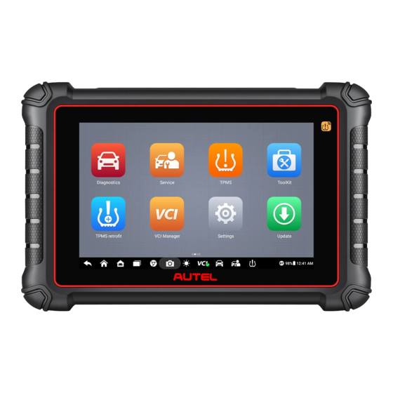
General Introduction When it comes to ultra-portability, the MaxiCOM tablet is your perfect companion. Installed with a fast quad-core processor, the MaxiCOM tablet offers maximum convenience and swift diagnosis. The intuitive user screen makes using the device effortless through an 8-inch LCD touchscreen that displays at 1280 x 800 quality. Together with the ability to quickly read and clear DTCs for all available modules of the majority of the makes and models on the market, the MaxiCOM tablet provides you with superior special functions, including Oil Reset, EPB (Electronic Parking Brake), SAS... - Page 10 A. Green Illuminates green when the tablet is charging and the battery level is above 90%. Illuminates green when the tablet is powered on and the battery level is above 15%. B. Yellow Illuminates yellow when the tablet is charging and the battery level is below 90%. C.
- Page 11 11. Power/Lock Button — press and hold to turn the device on/off, or tap to lock the screen. 2.1.2 Power Sources The tablet can receive power from any of the following sources: Internal battery pack Vehicle power External power supply 2.1.2.1 Internal Battery Pack The tablet can be powered via the internal rechargeable battery, which if fully charged...
-
Page 12: Technical Specifications
2.2 Technical Specifications Item Description Recommended Use Indoor Operating System Android Processor Quad-core processor Memory 4 GB RAM & 64 GB ROM Display 8-inch LCD touchscreen with 1280 x 800 resolution Type-C USB USB 2.0 Connectivity Wi-Fi ... -
Page 13: Accessory Kit
2.3 Accessory Kit Main Cable Connects the tablet to the vehicle’s ODBII port (DLC). USB Type-C Cable Use with the power adapter to provide power supply to the tablet. Power Adapter Together with the USB Type-C cable, connects the tablet to the external DC power port for power supply. -
Page 14: Getting Started
Getting Started Ensure the tablet is sufficiently charged or is connected to an external power supply (see Power Sources). Power Up Press and hold the Power/Lock button on the top-right corner of the tablet to power on the unit. The power LED will illuminate green. The system boots up and displays the lock screen. - Page 15 Accesses the system settings menu and general Settings tablet menu. See Settings. Accesses system software update menu. Update See Update. Synchronizes Autel's online service database with Support the tablet. See Support. Configures your unit to receive remote support using Remote the TeamViewer application.
- Page 16 Button Name Description Allows you to register an account, view, and edit your Autel User personal profile and link your device. Center Autel User Center. 3.1.2 Locator and Navigation Buttons Operations of the Navigation buttons at the bottom of the screen are described in the...
-
Page 17: Power Down
Button Name Description Display Brightness Automatically adjusts the display brightness. Diagnostic Shortcut Returns to the Diagnostics screen. Service Shortcut Returns to the Service screen. 3.1.3 System Status Icons As the tablet is working with the Android operating system, you may refer to Android documents for more information. -
Page 18: Diagnostics
Diagnostics The Diagnostics application can access the electronic control unit (ECU) for various vehicle control systems, including engine, transmission, antilock brake system (ABS), and airbag system (SRS). Getting Started Before using the Diagnostics application for the first time, make sure to establish a communication link between the tablet and the test vehicle using the main cable. -
Page 19: Vehicle Identification
Table 4-1 Top Toolbar Buttons Button Name Description Home Returns to the Job Menu. Tap to display a dropdown list: Tap Auto Detect for auto VIN detection. Tap Manual Input to enter VIN manually. Tap Scan VIN/License to scan the vehicle’s VIN or ... - Page 20 Manual Input Scan VIN/License Automatic Selection Manual Selection 4.2.1 Auto Detect The MaxiCOM diagnostics system features the latest VIN-based Auto Detect function to identify vehicles with just one tap, enabling you to quickly identify the exact vehicle and scan its available systems for fault codes. ...
- Page 21 Figure 4-3 Auto Detect Screen Tap Yes to confirm the vehicle profile or No if the information is not correct. Figure 4-4 Vehicle Profile Confirmation Screen The tablet will establish communication with the vehicle and read the control unit information. Choose Auto Scan to scan all the available systems or tap Control Unit to access a specific system to diagnose.
- Page 22 Figure 4-5 Diagnostic Menu Screen 4.2.2 Manual Input For vehicles that do not support the Auto Detect function, you may manually enter the vehicle VIN. To perform Manual Input Tap the Diagnostics application button from the Job Menu. The Vehicle Menu displays.
- Page 23 Tap OK. Once the vehicle is identified, the Vehicle Diagnostics screen will display. Tap the “cross” ( ) button at the top-right corner of the pop-up to exit Manual Input. 4.2.3 Scan VIN/License MaxiCOM tablet also supports the Scan VIN/License function. Enabling this function will automatically turn on the camera.
- Page 24 Select one of the three options and position the tablet to align the VIN, license number or the barcode within the scanning frame. The scan result will display on the Recognition Result screen. Tap OK to confirm the result, and then the vehicle information confirmation screen will display on the tablet.
- Page 25 4.2.4 Automatic Selection The vehicle VIN can also be automatically acquired after a vehicle manufacturer is selected. To perform Automatic Selection Tap the Diagnostics application button from the Job Menu. The Vehicle Menu displays. Select a manufacturer button. Tap Automatic Selection and the VIN information will be automatically acquired.
-
Page 26: Diagnostics Screen Layout
Diagnostics Screen Layout After the test vehicle is identified, the diagnostic menu will appear. This section consists of various commonly used functions, including Auto Scan and Control Unit. The available functions displayed vary depending on the test vehicle. Figure 4-11 Diagnostic Screen The diagnostics screen typically includes four sections. - Page 27 Button Name Description Saves and prints a copy of the displayed data. Print Printing Settings for additional information. Provides instructions or tips for operations of various Help diagnostics functions. Tap to open a sub menu. Tap Take a Screenshot to save the current page. ...
- Page 28 Status Information Bar The Status Information Bar at the top of the Main Section displays the following items: Menu Title — displays the menu heading of the Main Section. Battery Icon — indicates the battery status of the vehicle. Main Section The Main Section varies depending on the stage of operations, which displays vehicle identification selections, the main menu, test data, messages, instructions, and other diagnostics information.
-
Page 29: Diagnosis
Diagnosis The Diagnostics application enables a data link to the electronic control system of the test vehicle for vehicle diagnosis. The application performs functional tests and retrieves vehicle diagnostics information such as trouble and event codes and live data for various vehicle control systems, such as engine, transmission, and ABS. - Page 30 Main Section Column 1 — displays the system numbers. Column 2 — displays the scanned systems. Column 3 — displays the scan results. Fault(s) | #: Indicates there is/are fault code(s) detected; “#” indicates the quantity of detected faults. ...
- Page 31 Figure 4-13 Function Menu Screen Available functions may vary by vehicle. The function menu may include: ECU Information — displays detailed ECU information. Select to view the information screen. Trouble Codes — contains Read Codes and Erase Codes. The former displays ...
- Page 32 Figure 4-14 ECU Information Screen Diagnostics Toolbar Buttons — see Table 4-2 Diagnostics Toolbar Buttons detailed descriptions for the operations for each button. Main Section — the left column displays the item names, and the right column shows the specifications or descriptions. Function Button —...
- Page 33 Diagnostics Toolbar — see Table 4-2 Diagnostics Toolbar Buttons for details. Main Section Column 1 — displays the retrieved codes from the vehicle. Column 2 — indicates the status of the retrieved codes. Column 3 — displays detailed descriptions for the retrieved codes. ...
- Page 34 Gesture scrolling allows you to quickly move through the data list. Drag your finger(s) up or down to reposition the parameters being displayed if the data occupies more than one screen. The figure below shows a typical Live Data screen: Figure 4-16 Live Data Screen Diagnostics Toolbar Buttons —...
- Page 35 Figure 4-17 Display Mode Screen Each parameter item displays its selected mode independently. Analog Gauge Mode — displays the parameters in gauge charts. Text Mode — the default mode that displays the parameters as a text list. NOTE Status parameters, such as a switch reading like ON, OFF, ACTIVE, and ABORT, can only be displayed in Text Mode.
- Page 36 Settings Button (SetY) — sets the minimum and maximum values of the Y axis. Scale Button — changes the scale values. There are two scale buttons, displayed above the waveform graph to the right side, which can be used to change the scale values of the X axis and Y axis of the graph.
- Page 37 Figure 4-19 Waveform Edit Screen Digital Gauge Mode — displays the parameters in the form of a digital gauge graph. Trigger Settings On the Trigger Settings screen, you can set a standard range by filling in a minimum value and a maximum value. When exceeding this range, the trigger function will be executed and the tablet will automatically record and save the generated data.
- Page 38 Two buttons and two input boxes are available in the Trigger Settings screen. Trigger — switches the trigger on and off. The trigger is ON by default. Buzzer Alarm — switches the alarm on and off. The alarm function makes a beeping sound to alert you when the data reading reaches the preset minimum or maximum values.
- Page 39 This mode only supports quantitative parameters that can be represented digitally. If non-digital parameters are selected, a message will display advising the user that the selected parameters are not supported in this mode and to select 2 to 5 digital parameters. Tap Got It to return to the previous screen and select supported parameters.
- Page 40 Flag — displays when the Record function is applied. Tap to set flags to mark points of interest when recording data. Notes can be added during playback in Review or Data Manager. Select the preset flag to open a popup window and display a virtual keyboard to enter notes.
- Page 41 Figure 4-21 Active Test Screen The function buttons in the lower-right corner of the Active Test screen manipulate the test signals. Operational instructions are displayed in the main section of the test screen. Follow the on-screen instructions and make appropriate selections to complete the tests. Tap the ESC button to exit the test when finished.
-
Page 42: Generic Obdii Operations
Figure 4-23 Special Function Screen 2 List Tab Page: Column 1 — displays the description of the function being performed or the live data corresponding to the special function. Column 2 — displays the execution status such as Completed or Activated or the corresponding live data values. - Page 43 Protocol — select to open a submenu of available protocols. A communications protocol is a standardized way of data communication between an ECM and a diagnostic tool. Global OBD may use several different communications protocols. Select a specific protocol under the Protocol option. Wait for the OBDII Diagnostics Menu to appear.
- Page 44 Figure 4-25 DTC & FFD Menu Screen Current Codes Current codes are emissions-related DTCs from the ECU of the vehicle. OBDII/EOBD codes are prioritized according to their emissions severity, with higher- priority codes overwriting lower-priority ones. The priority of the code determines the illumination of the Malfunction Indicator Lamp (MIL) and the codes erase procedure.
- Page 45 Ready” or “Not Complete”. A confirmation screen will appear when the Clear Codes option is selected to prevent accidental loss of data. Select Yes on the confirmation screen to continue or No to exit. I/M Readiness This function is used to check the readiness of the monitoring system. It is an excellent function to use prior to having a vehicle inspected for local emissions compliance.
-
Page 46: Diagnostic Reports
Diagnostic Reports 4.6.1 Pre-Scan and Post-Scan Functions After performing pre-scan and post-scan functions by entering the same maintenance order number, tap Data Manager > Vehicle History to select the historical test record named with the maintenance order number. Both the pre-scan and post-scan results will be displayed in the same historical test record, which can be generated as a PDF report for easy data comparison. - Page 47 Figure 4-26 History Screen Select a record and tap the button on the upper-right corner. Figure 4-27 Historical Test Screen Tap Get Report. Enter the license plate and current mileage. Tap Save. Via the functions on the Diagnostics Toolbar The diagnostic report can also be viewed from such diagnostic function screens as Auto scan and Trouble codes.
- Page 48 Tap the button in the diagnostics toolbar and select Save Report. Enter the license number and current mileage. Tap Save > View Report and then select a report to view. Figure 4-28 Trouble Codes Screen 4.6.2.2 Diagnostics Report Viewing All the saved reports can be viewed in the Data Manager application.
- Page 49 4.6.2.3 Diagnostics Report Cloud Sharing Tap Data Manager > Cloud Report to enter the Report List screen. Figure 4-29 Report List 1 NOTE Note that if the report displays , it means the report has been uploaded to the cloud successfully, and you can share the report with others;...
-
Page 50: Exiting Diagnostics
Exiting Diagnostics The Diagnostics application remains open as long as there is an active communication with the vehicle. You must exit the diagnostics operation to stop all communications with the vehicle before closing the Diagnostics application. NOTE Damage to the vehicle electronic control module (ECM) may occur if communication is disrupted. -
Page 51: Service
Service The Service application is specially designed to provide quick access to the vehicle systems for various scheduled service and maintenance tasks. The typical service operation screen is a series of menu-driven commands. Follow the on-screen instructions to select appropriate options, enter values or data, and perform necessary actions. -
Page 52: Battery Management System (Bms) Service
Ensure that the EPB control system is reactivated after the maintenance work has been completed. NOTE Autel accepts no responsibility for any accident or injury arising from the maintenance of the EPB system. Battery Management System (BMS) Service The BMS (Battery Management System) allows the tool to evaluate the battery charge state, monitor the closed-circuit current, register the battery replacement, and activate the rest state of the vehicle. -
Page 53: Steering Angle Sensor (Sas) Service
NOTE AUTEL accepts no responsibility for any accident or injury arising from servicing the SAS system. When interpreting DTCs retrieved from the vehicle, always follow the manufacturer’s recommendation for repair. ... -
Page 54: Tire Pressure Monitor System (Tpms) Service
Before performing a forced DPF regeneration using the tool, check the following items: The fuel light is not on. No DPF-relevant faults stored in system. The vehicle has the specified engine oil. The oil for diesel is not contaminated. IMPORTANT Before diagnosing a problem vehicle and attempting to perform an emergency regeneration, it is important to obtain a full diagnostic log and read out relevant measured... - Page 55 transponder sends a signal with a unique identification code to the reader, which relays it to a receiver in the vehicle's computer control module. If the code is correct, the computer allows the fuel supply and ignition systems to operate and start the car. If the code is incorrect or absent, the computer disables the system, and the car will be unable to start until the correct key is placed in the ignition.
-
Page 56: Oem Authorization
OEM Authorization The OEM Authorization application allows to unlock the gateway ECU (CGW) for some vehicles to perform advanced diagnostics tests. NOTE Make sure the tablet is connected to the Internet before launching the OEM Authorization application. To unlock the gateway ECU (CGW) Connect the Diagnostics Platform to the vehicle using the Main Cable. -
Page 57: Data Manager
Data Manager The Data Manager application allows you to store, print, and review the saved files, manage the workshop information, customer information records and keep test vehicle history records. Selecting the Data Manager application opens the file system menu. There are nine main functions available. -
Page 58: Vehicle History
Button Name Description Tap to view the local reports on your tablet. If the report is successfully Cloud Report uploaded to cloud, you can also share the report with others. Tap to review the reports stored as PDF format. Review Data Tap to review the recorded data. - Page 59 Top Toolbar Buttons — navigation and application controls. Main Section — displays all vehicle test records. To activate a test session for the recorded vehicle Tap Data Manager on the Job Menu. Select Vehicle History to open the screen. Tap Diagnostics or Service to select diagnostic test records or service test records.
-
Page 60: Workshop Information
To edit the Test History Tap Data Manager on the Job Menu. Select Vehicle History. Select the specific vehicle record thumbnail from the main section. The vehicle test record sheet will appear. Tap Edit (a pen icon) to edit the record. Tap each item to enter information or attach data files or images. -
Page 61: Customer
To edit your Workshop Information Tap the Data Manager application on the Job Menu. Select Workshop Information. Tap on each field to enter information. Tap Done to save the updated workshop information record, or tap Cancel to exit without saving. Customer The Customer function allows you to create and edit customer accounts. -
Page 62: Image
To delete a customer account Tap Data Manager on the Job Menu. Select Customer. Select a customer account by tapping the corresponding name card. A Customer Information record will appear. Tap Edit on the top toolbar to edit the record. Tap the Delete button on the top of the screen. -
Page 63: Cloud Report
Tap to display the editing toolbar to delete, print or Edit email images. Tap to close the editing toolbar or cancel file search. Cancel Print Tap to print the selected image. Delete Tap to delete the selected image. Email Tap to send the selected image to an email address. ... -
Page 64: Data Logging
On the Review Data main screen, select a record file to play back. Figure 7-6 Data Playback Screen Main Section — displays the recorded data frames. Navigation Toolbar — allows you to manipulate data playback. Use the Navigation Toolbar buttons to play back the recorded data from frame to frame. Tap Back to exit data playback. -
Page 65: Settings
Settings Selecting Settings application opens a setup screen, on which you can adjust default settings and view information about the MaxiCOM system. The following options are available for the MaxiCOM system settings: Unit Language Printing Settings Report Settings ... -
Page 66: Language
To install the MaxiSys Printer driver program Download the Maxi PC Suite software from www.autel.com > Support > Downloads > Autel Update Tools, and install it to your windows-based computer. Double click the Setup.exe item. Select the installation language and the wizard will load. -
Page 67: Report Settings
This section below describes how to receive files from the tablet and perform printing through the computer. NOTE Make sure the tablet is connected to the same network with your computer, either via Wi-Fi or LAN, before printing. Make sure the computer installed with the Printing Services program is connected to a printer. -
Page 68: Push Notifications
Push Notifications This option allows you to manage notifications. The Notification Preferences option is turned on by default and cannot be turned off by users so that certain system notifications such as system security warnings will not be blocked. To manage other notifications Tap the Settings application on the Job Menu. -
Page 69: Vehicle List
To safeguard the rights and interests of both software developers and users, we have provided a list of legal terms and statement information. Please take the time to read them attentively before utilizing the Autel software. 8.10 System Settings This function provides you with direct access to the Android system settings interface,... - Page 70 To check the MaxiCOM product information in About Tap Settings on the Job Menu. Tap About on the left column. The product information screen will appear on the right. Tap the Home button on the top-left corner to return to the Job Menu, or select another setting option for the system setup.
-
Page 71: Update
Member Center —tap to enter the Member Center screen. Refresh — refreshes the available update list. Information Bar — displays your Autel ID, the tablet model information, subscription validity period and other related information. Tap Renew to extend subscription. Main Section — displays the available updates. -
Page 72: Update Procedures
Ensure the tablet is connected to a power source with stable access to the Internet. NOTE Make sure the tablet is registered before activating the Update application. See Autel User Center for details. Tap Update on the Job Menu, or tap the update notification message when received. The Update application screen displays. -
Page 73: Member Center
When the updating process is completed, the software will be installed automatically. The previous version will be replaced. Member Center The Member Center section provides settings related to account management, rights collection, and event participation. Figure 9-3 Member Center Screen... -
Page 74: Support
10.1 Product Registration In order to get access to the Support platform and obtain update and other services from Autel, you are required to register the tablet the first time you use it. See Autel User Center for detailed information. - Page 75 User Information — displays detailed information of your registered online Autel account, such as your Autel ID, Name, Address, and other contact information. Device Information — displays the registered product information, including the serial number, registration date, expire date, and warranty period.
- Page 76 10.2.3 Training The Training section provides quick links to Autel’s online video library. Select a video channel by language to see all available online tutorial videos on topics such as product usage techniques and vehicle diagnostics practice. 10.2.4 The FAQ section provides comprehensive references for all questions frequently asked and answered about the use of Autel’s online member account, and shopping and...
-
Page 77: Remote Desktop
You can use the application to receive remote support from Autel’s support center, colleagues or friends, by allowing them to control your tablet on their PC via the TeamViewer software. - Page 78 A prompt will appear asking you to allow remote control on your device. Tap Allow to accept or Deny to reject. Refer to the associated TeamViewer documents for additional information.
-
Page 79: Maxiviewer
MaxiViewer The MaxiViewer application allows you to search the functions supported by our tools and the version information. There are two ways of searching, either by searching the product and the vehicle or searching the functions. To Search by the vehicle Tap the MaxiViewer application on the Job Menu. - Page 80 Figure 12-2 Function Viewer Screen 2...
-
Page 81: Quick Link
Quick Link The Quick Link application provides you with convenient access to Autel’s official website and many other well-known sites in automotive service industry to provide technical help, knowledge bases, forums, and training and expertise consultations. Figure 13-1 Quick Link Screen ... -
Page 82: Maxivideo
MaxiVideo The MaxiVideo application configures the MaxiCOM diagnostics device to operate as a digital video scope by simply connecting the tablet to a MaxiVideo Camera. This function allows you to examine difficult-to-reach areas normally hidden from sight, with the ability to record digital still images and videos, which offers you an economical solution to inspect machinery, facilities, and infrastructure in a safe and quick way. -
Page 83: Autel User Center
Tap Autel User Center from the Job Menu. The following screen displays. Figure 15-1 Autel User Center Screen If you already have an Autel ID, you can log in with your phone number and verification code, or tap Log In with Password to log in with your Autel ID and password. - Page 84 If you have an Autel account, sign in with your account ID and password and skip to step 7. If you are a new member to Autel, click the Register button to create your Autel Enter the required personal information in the input fields.
-
Page 85: Maintenance And Service
Maintenance and Service To ensure that the MaxiCOM tablet performs at its optimum level, we advise that the product maintenance instructions covered in this section is read and followed. 16.1 Maintenance Instructions The following shows how to maintain your devices, together with precautions to take. ... -
Page 86: Troubleshooting Checklist
Your device may have not been connected to the charger properly. Check the connector. NOTE If your problems persist, please contact Autel’s technical support personnel or your local selling agent. 16.3 About Battery Usage Your tablet is powered by a built-in Lithium-ion Polymer battery. This means that, unlike other forms of battery technology, you can recharge your battery while some charge remains without reducing your tablet’s autonomy due to the “battery memory effect”... -
Page 87: Service Procedures
Technical Support If you have any question or problem on the operation of the product, please contact us (see the following contact info) or your local distributor. Autel China Headquarters Phone: +86 (0755) 8614-7779 (Monday-Friday, 9AM-6PM Beijing Time) ... - Page 88 Email: imea-support@autel.com Address: 906-17, Preatoni Tower (Cluster L), Jumeirah Lakes Tower, DMCC, Dubai, UAE Web: www.autel.com Autel Latin America Mexico: Phone: +52 33 1001 7880 (Spanish in Mexico) Email: latsupport@autel.com Address: Avenida Americas 1905, 6B, Colonia Aldrete, Guadalajara, Jalisco,...
- Page 89 Web: www.autel.com/br 16.4.2 Repair Service If it becomes necessary to return your device for repair, please download the repair service form from www.autel.com, and fill it in. The following information must be included: Contact name Return address ...
-
Page 90: Compliance Information
Compliance Information FCC Compliance FCC ID: WQ8-DS900DV2231 This device complies with Part 15 of the FCC rules and Industry Canada’s license- exempt RSSs. Operation is subject to the following two conditions: This device may not cause harmful interference. This device must accept any interference received, including interference that may cause undesired operation. - Page 91 Changes or modifications not expressly approved by the party responsible for compliance could void the user’s authority to operate the equipment. IC WARNING This device complies with Industry Canada’s licence-exempt RSS standard(s). Operation is subject to the following two conditions: (1) this device may not cause interference, and (2) this device must accept any interference, including interference that may cause undesired operation of the device.
- Page 92 CE COMPLIANCE This product is declared to conform to the essential requirements of the following Directives and carries the CE mark accordingly: RED Directive 2014/53/EU...
-
Page 93: Warranty
Warranty 18.1 Limited One Year Warranty Autel Intelligent Technology Corp., Ltd. (the Company) warrants to the original retail purchaser of this MaxiCOM diagnostic device, that should this product or any part thereof during normal consumer usage and conditions, be proven defective in material or...
Need help?
Do you have a question about the MaxiCOM MK900 and is the answer not in the manual?
Questions and answers