Table of Contents
Advertisement
Quick Links
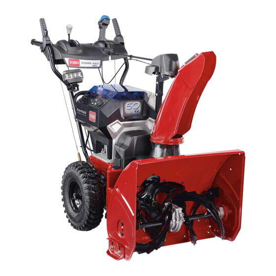
Power Max
Model No. 39924—Serial No. 400000000 and Up
Introduction
This machine is intended to be used by residential
homeowners. It is designed primarily for removing
snow from paved surfaces, such as driveways and
sidewalks, and other surfaces for traffic on residential
or commercial properties. It is not designed for
removing materials other than snow. It is designed to
use Toro Flex-Force lithium-ion battery pack Model
88675 (2 provided with Model 39924), 88660, 88650,
88640, 88625, or 88620. These battery packs are
designed to be charged only by battery charger
Models 88602 (provided with Model 39926), 88605,
or 88610. Using this product for purposes other than
its intended use could prove dangerous to you and
bystanders.
Read this information carefully to learn how to operate
and maintain your product properly and to avoid
injury and product damage. You are responsible for
operating the product properly and safely.
Visit www.Toro.com for product safety and operation
training materials, accessory information, help finding
a dealer, or to register your product.
Whenever you need service, genuine Toro parts, or
additional information, contact an Authorized Service
Dealer or Toro Customer Service and have the model
and serial numbers of your product ready.
identifies the location of the model and serial numbers
on the product. Write the numbers in the space
provided.
Important:
With your mobile device, you can
scan the QR code on the serial number decal (if
equipped) to access warranty, parts, and other
product information.
© 2021—The Toro® Company
8111 Lyndale Avenue South
Bloomington, MN 55420
®
e24 60V Snowthrower
This manual identifies potential hazards and has
safety messages identified by the safety-alert symbol
Figure 1
(Figure
serious injury or death if you do not follow the
recommended precautions.
This manual uses 2 words to highlight information.
Important calls attention to special mechanical
information and Note emphasizes general information
worthy of special attention.
Register at www.Toro.com.
Figure 1
1. Model and serial number location
Model No.
Serial No.
2), which signals a hazard that may cause
Figure 2
Safety-alert symbol
Original Instructions (EN)
Printed in Mexico
All Rights Reserved
Form No. 3450-403 Rev B
Operator's Manual
g344085
g000502
*3450-403*
Advertisement
Table of Contents

Related Manuals for Toro Power Max 39924


Summary of Contents for Toro Power Max 39924
-
Page 1: Introduction
Whenever you need service, genuine Toro parts, or additional information, contact an Authorized Service This manual identifies potential hazards and has Dealer or Toro Customer Service and have the model safety messages identified by the safety-alert symbol and serial numbers of your product ready. -
Page 2: Table Of Contents
Contents WARNING CALIFORNIA Introduction ............... 1 Safety ............... 3 Proposition 65 Warning Safety and Instructional Decals ......6 The power cord on this product contains Setup ................ 9 lead, a chemical known to the State 1 Mounting the Battery Charger of California to cause birth defects (Optional) ............ -
Page 3: Safety
Charge the battery pack with only the battery including the following: charger specified by Toro. A charger suitable for I. Training 1 type of battery pack may create a risk of fire when used with another battery pack. - Page 4 68°C (154°F) or incinerate come into contact with the liquid, flush with it. Replace the battery pack with a genuine Toro water. If the liquid contacts your eyes, seek battery pack only; using another type of battery medical help.
- Page 5 Do not dispose of the battery in a fire. The cell may explode. Check with local codes for possible special disposal instructions. SAVE THESE INSTRUCTIONS...
-
Page 6: Safety And Instructional Decals
Safety and Instructional Decals Safety decals and instructions are easily visible to the operator and are located near any area of potential danger. Replace any decal that is damaged or missing. decal94-8072 94-8072 decal121-6823 121-6823 decal121-6817 121-6817 1. Fast 3. Slow 2. - Page 7 decal137-6249 137-6249 1. Squeeze the lever to engage the traction drive. 4. Cutting/dismemberment of fingers or hand, impeller blade—keep away from moving parts; keep all guards and shields in place; remove the key from the ignition before servicing the machine. 2.
- Page 8 decal137-9456 137-9456 1. Read the Operator’s 3. Do not expose to rain. Manual. 2. Keep away from open fire or flames. decal137-9461 137-9461 1. Battery charge status decal133-8061 133-8061...
-
Page 9: Setup
Setup Important: The battery pack is not fully charged when you purchase it. Before using the machine for the first time, refer to Charging the Battery Pack (page 18). Mounting the Battery Charger (Optional) Parts needed for this procedure: Mounting hardware (not included) Procedure If desired, mount the battery charger securely on a wall using the wall-mount key holes on the back of the charger. -
Page 10: Installing The Chute
Installing the Chute No Parts Required Procedure g359038... -
Page 11: Installing The Upper Handle
Installing the Upper Handle No Parts Required Procedure g344102 Installing the Traction-Control Linkage No Parts Required Procedure g344089... -
Page 12: Installing The Chute-Control Rod
Installing the Chute-Control Rod No Parts Required Procedure g344086... -
Page 13: Installing The Snow-Cleanout Tool
Installing the Snow-Cleanout Tool No Parts Required Procedure g344095 Checking the Tire Pressure No Parts Required Procedure g344084... -
Page 14: Checking The Skids And Scraper
Move the speed selector to Position R1; refer to Operating the Speed Selector (page 19). Squeeze the left (traction) lever to the handgrip (Figure 10). Checking the Skids and Scraper No Parts Required Procedure Refer to Checking and Adjusting the Skids and g001011 Scraper (page 23). -
Page 15: Product Overview
Product Overview g347780 Figure 12 1. Battery charge lights 3. Key switch in O position 2. ECO button g344092 Figure 13 g372038 1. Snow-cleanout tool (attached to the handle) Figure 11 1. Handgrip (2) 10. Discharge chute 2. Auger/impeller lever 11. -
Page 16: Specifications
A selection of Toro approved attachments and accessories is available for use with the machine to enhance and expand its capabilities. Contact your Authorized Service Dealer or authorized Toro distributor or go to www.Toro.com for a list of all g348180 approved attachments and accessories. Figure 15... -
Page 17: Checking The State Of Charge
Checking the State of Charge You can view the state of charge of each installed battery; turn the key to the A position (Figure CCESSORY 16). The position of each set of lights corresponds to the related battery cavity. If the battery state of charge is too low and needs to be charged, or if there is no battery in the corresponding cavity, the battery presence light does not turn on. -
Page 18: Charging The Battery Pack
Charging the Battery Pack To remove the battery pack, slide the battery backward out of the charger. Important: The battery pack is not fully charged Refer to the following table to interpret the LED when you purchase it. Before using the tool for indicator light on the battery charger. -
Page 19: Operating The Traction Drive
Operating the Traction Operating the Speed Drive Selector The speed selector has 6 forward and 2 reverse CAUTION gears. To change speeds, release the traction lever and shift the speed-selector lever to the desired If the traction drive is not properly adjusted, position (Figure 21). -
Page 20: Operating The Quick Stick
Important: When you engage both the auger/impeller lever and the traction lever, the traction lever locks the auger/impeller lever down, freeing your right hand. To release both levers, simply release the left (traction) lever. If the auger and impeller continue to rotate when you release the auger/impeller lever, do not operate the machine. -
Page 21: Clearing A Clogged Discharge Chute
Clearing a Clogged Operating Tips Discharge Chute DANGER When the machine is in operation, the impeller WARNING and auger rotate and can injure or amputate If the auger/impeller is running but there is no hands or feet. snow coming out of the discharge chute, the •... -
Page 22: After Operation
Preventing Freeze-up after After Operation Shutting Off the Machine • In snowy and cold conditions, some controls and moving parts may freeze. Do not use excessive Release the traction and auger/impeller levers. force when trying to operate frozen controls. Turn the key to the O position and remove it If you have difficulty operating any control or part, from the control panel... -
Page 23: Maintenance
Maintenance Recommended Maintenance Schedule(s) Maintenance Service Maintenance Procedure Interval • Inspect the traction cable and adjust it if necessary. After the first 2 hours • Inspect the auger/impeller cable and adjust it if necessary. • Check the skids and the scraper and adjust them if necessary. •... -
Page 24: Checking And Adjusting The Traction Cable
Ensure that the scraper is 3 mm (1/8 inch) above and parallel to a level surface. Note: If the pavement is cracked, rough, or uneven, adjust the skids to raise the scraper. For gravel surfaces, adjust the skids further down to prevent the machine from picking up rocks. -
Page 25: Checking And Adjusting The Auger/Impeller Cable
Checking and Adjusting the Auger/Impeller Cable Service Interval: After the first 2 hours—Inspect the auger/impeller cable and adjust it if necessary. Yearly—Inspect the auger/impeller cable and adjust or replace it if necessary. Loosen the jam nut (Figure 31). Engage the auger/impeller lever and hold it in place (Figure 30). -
Page 26: Checking The Auger-Gearbox-Oil Level
Checking the Lubricating the Hex Shaft Auger-Gearbox-Oil Level Service Interval: Yearly—Lubricate the hex shaft. Lightly lubricate the hex shaft yearly with automotive Service Interval: Yearly—Check the auger-gearbox engine oil (Figure 33). oil and add oil if necessary. Move the machine to a level surface. Clean the area around the pipe plug (Figure 32). -
Page 27: Adjusting The Discharge-Chute Latch
Move the speed-selector lever forward and rearward a few times. Install the back cover and return the machine to the operating position. Adjusting the Discharge-Chute Latch If the discharge chute does not lock into the desired position or does not unlock so that you can move it to another position, adjust the discharge-chute latch. -
Page 28: Storage
If you are located outside of the US for the off-season, charge it until 2 or 3 LED and Canada, please contact your authorized Toro distributor. indicators turn green on the battery. Do not store a fully charged or fully depleted battery. When... -
Page 29: Troubleshooting
5. The auger/impeller drive belt is loose 5. Install and/or adjust the auger/impeller or is off the pulley. drive belt; refer to www.Toro.com for servicing information or take the machine to an Authorized Service Dealer. 6. The auger/impeller drive belt is worn 6. - Page 30 Problem Possible Cause Corrective Action The machine does not properly clear the 1. The skids and/or scraper are not 1. Adjust the skids and/or the scraper. snow off the surface. properly adjusted. 2. The pressure in the tires is not equal. 2.
- Page 31 While the exposure from Toro products may be negligible or well within the “no significant risk” range, out of an abundance of caution, Toro has elected to provide the Prop 65 warnings. Moreover, if Toro does not provide these warnings, it could be sued by the State of California or by private parties seeking to enforce Prop 65 and subject to substantial penalties.