Table of Contents
Advertisement
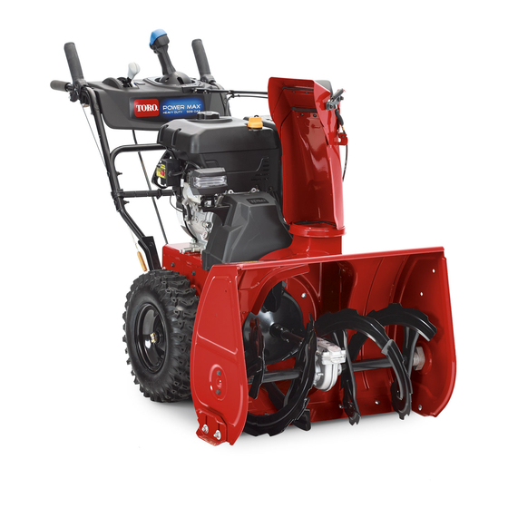
Power Max Heavy Duty 926/928/1028 OXE
Snowthrower
Model No. 38820—Serial No. 313000001 and Up
Model No. 38822—Serial No. 313000001 and Up
Model No. 38824—Serial No. 313000001 and Up
Introduction
This machine is intended to be used by residential
homeowners or professional, hired operators. It is
designed for removing snow from paved surfaces, such
as driveways and sidewalks, and other surfaces for
traffic on residential or commercial properties. It is not
designed for removing materials other than snow.
Read this information carefully to learn how to operate and
maintain your machine properly and to avoid injury and
machine damage. You are responsible for operating the
machine properly and safely.
You may contact Toro directly at www.Toro.com for machine
and accessory information, help finding a dealer, or to register
your machine.
Whenever you need service, genuine Toro parts, or additional
information, contact an Authorized Service Dealer or Toro
Customer Service and have the model and serial numbers of
your machine ready. Figure 1 identifies the location of the
model and serial numbers on the machine. Write the numbers
in the space provided.
© 2012—The Toro® Company
8111 Lyndale Avenue South
Bloomington, MN 55420
This manual identifies potential hazards and has safety
messages identified by the safety alert symbol (Figure 2),
which signals a hazard that may cause serious injury or death
if you do not follow the recommended precautions.
This manual uses 2 words to highlight information.
Important calls attention to special mechanical information
and Note emphasizes general information worthy of special
attention.
Register at www.Toro.com.
G016493
Figure 1
1. Model and serial number location
Model No.
Serial No.
Figure 2
1. Safety alert symbol
Original Instructions (EN)
All Rights Reserved *3369-561* A
Printed in the USA
Form No. 3369-561 Rev A
Operator's Manual
ST OP
1
Advertisement
Table of Contents

Related Manuals for Toro power max 926


Summary of Contents for Toro power max 926
-
Page 1: Introduction
You are responsible for operating the Figure 1 machine properly and safely. 1. Model and serial number location You may contact Toro directly at www.Toro.com for machine and accessory information, help finding a dealer, or to register your machine. Model No. -
Page 2: Table Of Contents
Training ..............3 Preparation............. 3 Operation............... 3 Clearing a Clogged Discharge Chute ......4 Maintenance and Storage.......... 4 Toro Snowthrower Safety ......... 4 Sound Pressure ............5 Sound Power ............5 Vibration..............5 Safety and Instructional Decals ......... 5 Setup ................7 1 Installing the Upper Handle........ -
Page 3: Training
Safety – Keep the nozzle in contact with the rim of the fuel tank or container opening at all times, until refueling is complete. Do not use a nozzle lock-open device. This machine meets or exceeds the ISO 8437 specifications of the International Standards –... -
Page 4: Clearing A Clogged Discharge Chute
Store fuel in an approved fuel container. Remove the key The following list contains safety information specific to Toro from the ignition switch before storing the machine. machines or other safety information that you must know. -
Page 5: Sound Pressure
Sound Pressure This machine has a sound pressure level at the operator’s left ear of 87.5 dBA (models 38820 and 38822) and 87.3 dBA (model 38824), and a sound pressure level at the operator’s right ear of 86.6 dBA (models 38820 and 38822) and 85.7 dBA (model 38824). - Page 6 112-6627 1. Left turn control 3. Warning—read the 5. Cutting/dismemberment 7. Auger/impeller Operator's Manual. hazard, impeller—keep drive—squeeze the lever to away from moving parts; engage; release the lever remove the ignition key and to disengage. read the instructions before servicing or performing maintenance.
-
Page 7: Setup
Setup Loose Parts Use the chart below to verify that all parts have been shipped. Procedure Description Qty. Handle bolts Curved washers Install the upper handle. Locknuts – No parts required Install the wheel clutch cable ends – No parts required Install the traction control linkage. -
Page 8: Installing The Upper Handle
Installing the Upper Handle Parts needed for this procedure: Handle bolts Curved washers Locknuts Procedure Figure 5 Note: Do not remove the rubber band on the cables until you have installed the upper handle. 1. Lift and rotate the upper handle and position it over the lower handle (Figure 4). -
Page 9: Installing The Traction Control Linkage
Figure 10 Figure 7 Note: The gap should be approximately the thickness 1. Wheel clutch lever of a pencil (1/4 inch or 6 mm). If it is greater, loosen the cable clamp nut, slide the cable jacket up slightly, 3. Remove the nut and washer from the handle, attach tighten the cable clamp nut, and check the gap again. -
Page 10: Installing The Chute Control Rod
Note: For easier installation, look down through the opening in the speed selector (Figure 14). Figure 14 Figure 12 1. Speed selector 1. Speed selector lever 3. Inner washer 2. Trunnion 4. Outer washer Note: To make installation easier, leave the flat washer on the trunnion (Figure 12). -
Page 11: Connecting The Wire To The Headlight
7. Hold the blue trigger cap down and rotate the Quick Stick in a circle to ensure that the chute and deflector operate smoothly. Connecting the Wire to the Headlight g018656 Figure 15 Parts needed for this procedure: 1. Short rod 2. -
Page 12: Filling The Engine With Oil
Filling the Engine with Oil No Parts Required Procedure Your machine comes with oil in the engine crankcase. Note: Before starting the engine, check the oil level and add oil if necessary. Use automotive detergent oil with an API service classification of SF, SG, SH, SJ, SL, or higher. -
Page 13: Checking The Traction Drive Operation
6. Squeeze the left hand (traction) lever to the hand-grip (Figure 21). The machine should move forward. If the machine does not move or moves rearward, complete the Checking the Traction Drive following: Operation A. Release the traction lever and stop the engine. B. -
Page 14: Product Overview
Product Overview Figure 24 1. Snow cleanout tool (attached to the handle) Operation Note: Determine the left and right sides of the machine from the normal operating position. Filling the Fuel Tank DANGER Gasoline is extremely flammable and explosive. A fire or explosion from gasoline can burn you and others. -
Page 15: Starting The Engine
Starting the Engine • For best results, use only clean, fresh, unleaded gasoline with an octane rating of 87 or higher ((R+M)/2 rating 1. Check the engine oil level. Refer to Checking the method). Engine Oil Level in Maintenance. • Oxygenated fuel with up to 10% ethanol or 15% MTBE 2. - Page 16 4. Firmly push in the primer with your thumb as indicated 5. Move the choke to the Choke position (Figure 29). by the chart below, holding the primer in for a second before releasing it each time (Figure 28). Number of primes Temperature 0°F ( -18°C) or above -10°F to 0°F (-23°C to -18°C)
-
Page 17: Stopping The Engine
Stopping the Engine 1. Move the throttle to the Slow position, and then to the Stop position (Figure 32) to kill the engine. The engine can also be stopped by pulling the ignition key outward to the middle position. g018812 Figure 31 1. -
Page 18: Operating The Traction Drive
Operating the Traction Drive CAUTION If the traction drive is not properly adjusted, the machine may move in the direction opposite of what you intended, causing injury and/or property damage. Figure 35 Carefully check the traction drive and adjust it properly, if necessary;... -
Page 19: Operating The Auger/Impeller Drive
Operating the Auger/Impeller Drive 1. To engage the auger/ impeller drive, squeeze the right hand (auger/ impeller) lever to the handgrip (Figure 38). Figure 39 Moving the Discharge Chute Figure 38 Hold the blue trigger cap down and move the Quick Stick to the left to move the discharge chute to the left;... -
Page 20: Unclogging The Discharge Chute
from freezing. Stop the engine, wait for all moving parts to stop, and remove all ice and snow from the machine. • With the engine off, pull the recoil starter handle several times and push the electric-starter button once to prevent the recoil starter and electric starter from freezing up. -
Page 21: Maintenance
• Have an Authorized Service Dealer inspect and replace the traction drive belt and/or the auger/impeller drive belt, if necessary. Important: You can find more information about maintaining and servicing your machine at www.Toro.com. Preparing for Maintenance 1. Move the machine to a level surface. -
Page 22: Checking And Adjusting The Traction Cable
Check the skids to ensure that the auger does not contact With the traction lever disengaged, check the pin in the the paved or gravel surface. Adjust the skids as needed to elongated slot in the left side of the machine above the compensate for wear. -
Page 23: Changing The Engine Oil
Changing the Engine Oil Service Interval: After the first 5 hours—Change the engine oil. Every 50 hours—Change the engine oil. Change the engine oil every 25 operating hours when operating the engine under a heavy load. If possible, run the engine just before changing the oil because warm oil flows better and carries more contaminants. -
Page 24: Replacing The Spark Plug
4. Set the gap between the electrodes on a new spark plug at 0.030 inch (0.76 mm) (Figure 51). Wait until the engine is cool to replace the spark plug. Use a Toro spark plug or equivalent (Champion® RN9YC or NGK BPR6ES). 1. Remove the boot (Figure 49). Figure 51 1. -
Page 25: Replacing The Drive Belts
Replacing the Drive Belts If the auger/impeller drive belt or the traction drive belt becomes worn, oil-soaked, or otherwise damaged, have an Authorized Service Dealer replace the belt. Replacing the Headlight Bulb Use a GE 899 37W halogen light bulb. Do not touch the Figure 52 bulb with your hands or allow dirt or moisture to come into contact with the bulb. -
Page 26: Storage
Storage WARNING • Gasoline vapors can explode. • Do not store gasoline more than 30 days. Figure 58 • Do not store the machine in an enclosure near an open flame. 5. Turn the base of the bulb clockwise until it is snug (Figure 59). -
Page 27: Troubleshooting
Troubleshooting Problem Possible Cause Corrective Action Electric starter does not turn (electric-start 1. The power cord is disconnected at the 1. Connect the power cord to the outlet models only) outlet or the machine. and/or the machine. 2. The power cord is worn, corroded, or 2. - Page 28 5. Unclog the discharge chute. 6. The auger/impeller drive belt is loose 6. Install and/or adjust the auger/impeller or is off the pulley. drive belt; refer to www.Toro.com for servicing information or take the machine to an Authorized Service Dealer.
- Page 29 Notes:...
- Page 30 Notes:...
- Page 31 The Information Toro Collects Toro Warranty Company (Toro) respects your privacy. In order to process your warranty claim and contact you in the event of a product recall, we ask you to share certain personal information with us, either directly or through your local Toro dealer.
- Page 32 Toro's option, under warranty at no cost for parts and labor. Frame failure due to misuse or abuse and failure or repair required due to rust or corrosion are not covered.