Table of Contents
Advertisement
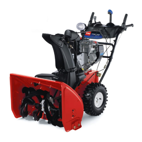
Power Max
Model No. 38637—Serial No. 280000001 and Up
Introduction
Read this information carefully to learn how to operate
and maintain your product properly and to avoid injury
and product damage. You are responsible for operating
the product properly and safely.
You may contact Toro directly at www.Toro.com for
product and accessory information, help finding a
dealer, or to register your product.
Whenever you need service, genuine Toro parts, or
additional information, contact an Authorized Service
Dealer or Toro Customer Service and have the model
and serial numbers of your product ready. Figure 1
identifies the location of the model and serial numbers
on the product. Write the numbers in the space
provided.
Figure 1
1. Model and serial number location
Model No.
Serial No.
This manual identifies potential hazards and has
safety messages identified by the safety alert symbol
(Figure 2), which signals a hazard that may cause serious
© 2008—The Toro® Company
8111 Lyndale Avenue South
Bloomington, MN 55420
®
828 OXE Snowthrower
injury or death if you do not follow the recommended
precautions.
1. Safety alert symbol
This manual uses 2 words to highlight information.
Important calls attention to special mechanical
information and Note emphasizes general information
worthy of special attention.
Replacement Engine Owner's Manuals may be
ordered through the engine manufacturer.
Register at www.Toro.com.
Form No. 3358-566 Rev C
Operator's Manual
Figure 2
Original Instructions (EN)
Printed in the USA
All Rights Reserved
Advertisement
Table of Contents

Related Manuals for Toro Power Max 828 OXE


Summary of Contents for Toro Power Max 828 OXE
- Page 1 Important calls attention to special mechanical additional information, contact an Authorized Service information and Note emphasizes general information Dealer or Toro Customer Service and have the model worthy of special attention. and serial numbers of your product ready. Figure 1 identifies the location of the model and serial numbers Replacement Engine Owner’s Manuals may be...
-
Page 2: Before Operating
Safety Before Operating Caution: Improper use may result in loss of fingers, hands, or feet. Read and understand the contents of this manual before operating the snowthrower There is a high-speed Become familiar with all controls and know impeller close to the how to stop the engine quickly opening. -
Page 3: Maintenance And Storage
• Do not clear snow across the face of slopes. Exercise The following list contains safety information specific extreme caution when changing direction on slopes. to Toro products or other safety information that you Do not attempt to clear steep slopes. must know. -
Page 4: Sound Pressure
• If a shield, safety device, or decal is damaged, • Purchase only genuine Toro replacement parts and accessories. illegible, or lost, repair or replace it before beginning operation. Also, tighten any loose fasteners. - Page 5 112-6625 Reorder part no. 112-6629 1. Cutting/dismemberment hazard, impeller—do not place your hand in the chute; stop the engine before leaving the operator’s position, use the tool to clear the chute. 112-6627 1. Left turn control 3. Warning—read the 5. Cutting/dismemberment 7.
-
Page 6: Loose Parts
Briggs Part No. 276925 Briggs Part No. 277566 1. Warning—read the 3. Warning—toxic gas 1. When starting a cold 2. When starting a warm Operator’s Manual. inhalation hazard. engine, close the choke engine, open the choke 2. Warning—fire hazard. 4. Warning—hot and press the primer two and do not press the surface/burn hazard. -
Page 7: Installing The Upper Handle
1. Installing the Upper Handle 2. Installing the Wheel Clutch Cable Ends Handle bolts Curved washers Procedure Locknuts 1. Unwrap the cable ends from the lower handle (Figure 5). Procedure Note: Do not remove the rubber band on the cables until you have installed the upper handle. -
Page 8: Installing The Traction Control Linkage
Important: Ensure that the curved side of the cable clamp is against the handle and that the cable is routed below the clamp bolt. The cable must be in a straight line from the cable clamp to the point where it attaches to the wheel clutch lever. -
Page 9: Installing Chute Control Rod
6. Lift up on the speed control rod and insert the trunnion into the hole in the speed selector lever (Figure 11). Note: If the trunnion does not fit into the hole when you lift up on the speed control rod, rotate the trunnion upward or downward on the speed control rod until it fits. -
Page 10: Filling The Engine With Oil
6. Filling the Engine with Oil Procedure Your snowthrower comes with 20 oz. of oil in the engine crankcase. Note: Before starting the engine, check the oil level and add oil if necessary. Figure 16 Max. fill: 20 oz. (0.55 l), type: automotive detergent oil 1. -
Page 11: Checking The Skids And Scraper
8. Checking the Skids and 4. Release the traction lever. Scraper 5. Move the speed selector to the Position 1; refer to Operating the Speed Selector. Procedure 6. Squeeze the left hand (traction) lever to the hand-grip (Figure 19). Refer to Checking and Adjusting the Skids and Scraper The snowthrower should move forward. -
Page 12: Product Overview
Product Overview Figure 22 1. Snow cleanout tool (attached to the handle) Operation Note: Determine the left and right sides of the machine from the normal operating position. Filling the Fuel Tank Gasoline is extremely flammable and explosive. Figure 20 A fire or explosion from gasoline can burn you and others. -
Page 13: Starting The Engine
Figure 25 1. Ignition key Figure 23 1. 1-1/2 inch (3.8 cm) 4. Firmly push in the primer with your thumb 2 times (15°F or -9°C or above) or 4 times (below 15°F or -9°C), holding the primer in for a second before releasing it each time (Figure 26). -
Page 14: Stopping The Engine
maximum, then wait one minute before trying to start it again). If the engine still does not start, take the snowthrower to an Authorized Service Dealer for service. 8. Disconnect the power cord from the power outlet first and then from the snowthrower (electric start only). -
Page 15: Operating The Traction Drive
Figure 32 Figure 31 2. To stop the traction drive, release the traction lever. Using the Wheel Clutch Levers 5. Pull the recoil starter 3 or 4 times. This helps prevent the recoil starter from freezing up. The wheel clutch levers allow you to momentarily disengage the drive to one or both wheels with the Operating the Traction Drive traction drive lever still engaged. -
Page 16: Operating The Speed Selector
Momentarily squeezing and releasing the left or right levers, simply release the left hand (traction) wheel clutch lever also allows for steering adjustments to lever. keep the snowthrower going in a straight line, especially 3. If the auger and impeller continue to rotate when in deep snow. -
Page 17: Unclogging The Discharge Chute
Unclogging the Discharge Chute If the auger/impeller is running but there is no snow coming out of the discharge chute, the discharge chute may be clogged. • To unclog the discharge chute, stay in the operating position and release the left hand (traction) lever. While running the auger/impeller, push down on the handles to raise the front of the snowthrower a few inches (centimeters) off the pavement. -
Page 18: Operating Tips
Operating Tips When the snowthrower is in operation, the impeller and auger can rotate and cut off or injure hands and feet. • Before adjusting, cleaning, inspecting, troubleshooting, or repairing the snowthrower, stop the engine and wait for all moving parts to stop. Disconnect the wire from the spark plug and keep it away from the plug to prevent someone from accidentally starting the engine. -
Page 19: Recommended Maintenance Schedule(S)
Important: You can find more information about maintaining and servicing your snowthrower at www.Toro.com. Important: Refer to your engine operator’s manual for additional maintenance procedures. For engine adjustments, repairs, or warranty service not covered in this manual, contact an Authorized Briggs &... -
Page 20: Checking And Adjusting The Traction Cable
Checking and Adjusting the Checking and Adjusting the Skids and Scraper Traction Cable Service Interval: Yearly—Check the skids and the Service Interval: After the first 2 hours—Inspect scraper and adjust them if necessary. the traction cable and adjust it if necessary. -
Page 21: Checking And Adjusting The Auger/Impeller Cable
Figure 43 Figure 45 1. Jam nut 2. Turnbuckle 1. Tab 2. 1/16 inch (1.5 mm) Checking and Adjusting the 4. If the auger/impeller cable is not properly adjusted, Auger/Impeller Cable do the following steps: 5. Loosen the jam nut (Figure 46). Service Interval: After the first 2 hours—Inspect the auger/impeller cable and adjust it if necessary. -
Page 22: Checking The Auger Gearbox Oil Level
Checking the Auger Gearbox Oil Level Service Interval: Yearly—Check the auger gearbox oil and add oil if necessary. Figure 48 1. Move the snowthrower to a level surface. 1. Oil drain cap 2. Clean the area around the pipe plug (Figure 47). 2. -
Page 23: Replacing The Spark Plug
4. Remove the bracket thumb screw and the bracket (Figure 52). Figure 50 1. Back cover 4. Move the speed selector lever to Position R2. 5. Dip your finger in automotive engine oil and lightly lubricate hex shaft. 6. Move the speed selector lever to Position 6. 7. -
Page 24: Adjusting The Discharge Chute Latch
If the auger/impeller drive belt or the traction drive belt becomes worn, oil-soaked, or otherwise damaged, go 2. Loosen the bolt on the cable clamp (Figure 55). to www.Toro.com for additional service information or have an Authorized Service Dealer replace the belt. Replacing the Headlight Bulb Use a GE 892 16W halogen light bulb. - Page 25 Figure 58 3. Remove the bulb straight out from the back of the headlight (Figure 59). Figure 62 Figure 59 4. Insert a new bulb into the back of the headlight (Figure 60). Figure 60 5. Turn the base of the bulb clockwise until it is snug (Figure 61).
-
Page 26: Preparing The Snowthrower For Storage
Storage 16. Touch up chipped surfaces with paint available from an Authorized Service Dealer. Sand affected areas before painting, and use a rust preventative to prevent the metal parts from rusting. 17. Tighten all loose screws, bolts, and locknuts. Repair •... -
Page 27: Troubleshooting
5. Unclog the discharge chute. 6. The auger/impeller drive belt is loose 6. Install and/or adjust the auger/impeller or is off the pulley. drive belt; refer to www.Toro.com for servicing information or take the snowthrower to an Authorized Service Dealer. - Page 28 Corrective Action 7. The auger/impeller drive belt is worn 7. Replace the auger/impeller drive belt; or broken. refer to www.Toro.com for servicing information or take the snowthrower to an Authorized Service Dealer. Discharge chute either does not lock into 1. The discharge chute latch is not 1.
- Page 29 Notes:...
- Page 30 Notes:...
- Page 31 Spypros Stavrinides Limited Cyprus 357 22 434131 Surge Systems India Limited India 91 1 292299901 T-Markt Logistics Ltd Hungary 36 26 525 500 Toro Australia Australia 61 3 9580 7355 Toro Europe BVBA Belgium 32 14 562 960 374-0102 Rev B...
- Page 32 Contact your seller to arrange service of the product. If for any reason materials or workmanship. The following time periods apply from the date it is impossible for you to contact your seller, you may contact any Toro of original purchase: Authorized Distributor to arrange service.