Toro Reelmaster 3100-D Series Operator's Manual
5, 8, and 11-blade 27-inch and 8-blade 32-inch dpa cutting unit
Hide thumbs
Also See for Reelmaster 3100-D Series:
- Service manual (385 pages) ,
- Operator's manual (104 pages) ,
- Installation instructions manual (16 pages)
Table of Contents
Advertisement
Quick Links
Register at www.Toro.com.
Original Instructions (EN)
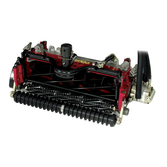
5, 8, and 11-Blade 27-inch and
8-Blade 32-inch DPA Cutting Unit
Reelmaster
®
3100-D Series Traction Unit
Model No. 03180—Serial No. 316000001 and Up
Model No. 03181—Serial No. 316000001 and Up
Model No. 03182—Serial No. 316000001 and Up
Model No. 03183—Serial No. 316000001 and Up
Form No. 3402-441 Rev B
*3402-441* B
Advertisement
Table of Contents

Related Manuals for Toro Reelmaster 3100-D Series


Summary of Contents for Toro Reelmaster 3100-D Series
- Page 1 3100-D Series Traction Unit Model No. 03180—Serial No. 316000001 and Up Model No. 03181—Serial No. 316000001 and Up Model No. 03182—Serial No. 316000001 and Up Model No. 03183—Serial No. 316000001 and Up *3402-441* B Register at www.Toro.com. Original Instructions (EN)
-
Page 2: Table Of Contents
You are responsible for operating the product properly and safely. You may contact Toro directly at www.Toro.com for product Contents safety and operation training materials, accessory information, help finding a dealer, or to register your product. -
Page 3: Safety
• To ensure optimum performance and continued safety unit is in safe operating condition. certification of the machine, use only genuine Toro • Wear appopriate clothing, including eye protection; replacement parts and accessories. Replacement parts substantial, slip-resistant footwear;... -
Page 4: Setup
Setup Loose Parts Use the chart below to verify that all parts have been shipped. Procedure Description Qty. Cutting unit Inspect the cutting unit. Use the kickstand when tipping the – No parts required cutting unit. – No parts required Adjust the rear shield. -
Page 5: Adjusting The Rear Shield
Figure 4 Figure 3 1. Rear shield 2. Cap screw 1. Cutting-unit kickstand Mounting the Counterweights Adjusting the Rear Shield No Parts Required No Parts Required Procedure Procedure All cutting units are shipped with the counterweight mounted to the left end of the cutting unit. Use the following diagram Under most conditions, the best dispersion is attained when to determine the position of the counterweights and reel the rear shield is closed (front discharge). -
Page 6: Installing The Fixed Plate Kit (Optional)
Installing the Fixed Plate Kit (Optional) Parts needed for this procedure: Fixed plate kit (not included) Procedure 1. Remove the nuts and washers securing the lift links to the cutting-unit side plate and carrier frame (Figure Figure 6 1. O-ring 3. - Page 7 Figure 9 1. Nuts 2. Fixed plate 3. Loosen the locknuts securing the height-of-cut brackets to the cutting-unit side plates (Figure 10). Figure 10 3. Adjusting screw 1. Height-of-cut bracket 2. Locknut 4. Remove the height-of-cut brackets and the roller from the cutting unit.
-
Page 8: Product Overview
After completing this procedure, always test the cutting its capabilities. Contact your Authorized Service Dealer or unit performance under your field conditions. You may Distributor or go to www.Toro.com for a list of all approved need to make further adjustments to obtain optimal cutting attachments and accessories performance. - Page 9 10. Test the cutting performance by inserting a long bedknife. strip of cutting performance paper (Toro Part No. Note: The position of the rear roller to the reel 125-5610) between reel and bedknife, perpendicular...
-
Page 10: Height-Of-Cut Chart Terms
Figure 15 1. Rear spacers 3. Aggressiveness of cut 2. Side-plate mounting flange g020698 Figure 14 1. Side-plate mounting cap screws Rear Spacers The number of rear spacers determines the aggressiveness Height-of-Cut Chart Terms of cut for the cutting unit. For a given height of cut, adding spacers, below the side plate mounting flange, increases the aggressiveness of the cutting unit. - Page 11 Adjusting the Height of Cut 35 mm (1.375 Less inches) Normal 1. Loosen the locknuts securing the height-of-cut brackets More to the cutting-unit side plates (Figure 16). 38 mm (1.500 Less inches) Normal More 41 mm (1.625 Less inches) Normal More 44 mm (1.750 Less...
- Page 12 Figure 19 1. Bedknife lip height* 6. To adjust the height of cut when fixed plate kits are installed on the cutting units, proceed as follows: • Remove the height-of-cut brackets and the front roller as described in Procedure 5 in the Setup section.
- Page 13 Toro Manual for Sharpening Reel and Rotary Mowers (Form No. 09168SL). Important: Light contact is preferred at all times.
-
Page 14: Maintenance
Maintenance 2. Using a rag or thickly padded glove, hold on to the reel blade and try to move the reel assembly side to side (Figure 24). Lubricating the Cutting Unit Each cutting unit has 6 grease fittings (Figure 22) that must be lubricated regularly with No. -
Page 15: Servicing The Bedknife
Checking the Top Grind Angle The angle that you use to grind your bedknives is very important. Use the angle indicator (Toro Part No. 131-6828) and the g027268 angle-indicator mount (Toro Part No. 131-6829) to check the angle that your grinder produces and then correct for Figure 26 any grinder inaccuracy. - Page 16 Figure 29 1. Angle-indicator mount 3. Bedknife 2. Edge of the magnet mated 4. Angle indicator with the edge of the bedknife 4. Place the angle indicator on the mount as shown in Figure Note: This is the angle that your grinder produces; it should be within 2 degrees of the recommended top grind angle.
-
Page 17: Servicing The Bedbar
Servicing the Bedbar Removing the Bedbar 1. Turn the bedbar-adjuster screws counterclockwise to back the bedknife away from the reel (Figure 30). Figure 32 1. Bedbar bolt 3. Steel washer 2. Nut 4. Nylon washer Assembling the Bedbar 1. Install the bedbar, positioning the mounting ears Figure 30 between the washer and the bedbar adjuster. -
Page 18: Servicing The Hd Dual Point Adjusters (Dpa)
Servicing the HD Dual Point 3. Align the keys on flange bushings to the slots in the frame and install the bushings (Figure 34). Adjusters (DPA) 4. Install a wave washer onto the adjuster shaft and slide 1. Remove all parts (refer to the Installation Instructions for the adjuster shaft into the flange bushings in the cutting the HD DPA Kit (Model No. -
Page 19: Servicing The Roller
Refer to your parts catalog or contact your (Figure 35) are available for servicing the roller. The Authorized Toro Distributor for assistance. Roller Rebuild Kit includes all the bearings, bearing Figure 35 1. Roller Rebuild Kit (Part No. 114-5430) 6. - Page 20 Notes:...
- Page 21 Notes:...
- Page 22 The method of transmission shall be electronic transmittal. This machinery shall not be put into service until incorporated into approved Toro models as indicated on the associated Declaration of Conformity and in accordance with all instructions, whereby it can be declared in conformity with all relevant Directives.
- Page 23 The Way Toro Uses Information Toro may use your personal information to process warranty claims, to contact you in the event of a product recall and for any other purpose which we tell you about. Toro may share your information with Toro's affiliates, dealers or other business partners in connection with any of these activities. We will not sell your personal information to any other company.
- Page 24 Countries Other than the United States or Canada Customers who have purchased Toro products exported from the United States or Canada should contact their Toro Distributor (Dealer) to obtain guarantee policies for your country, province, or state. If for any reason you are dissatisfied with your Distributor's service or have difficulty obtaining guarantee information, contact the Toro importer.