Table of Contents
Advertisement
Quick Links
NORTHSTAR AVIONICS
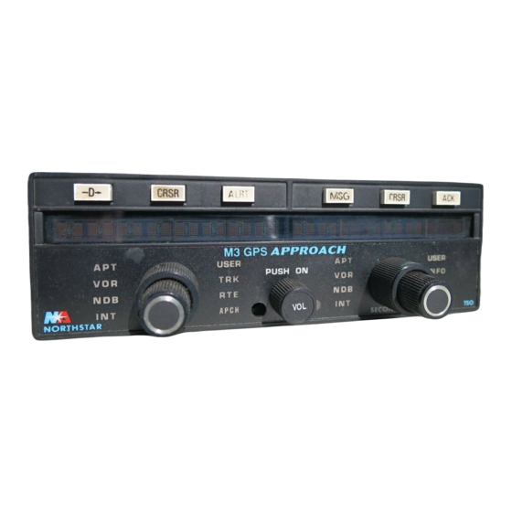
M3 GPS APPROACH
D
APT
VOR
NDB
INT
NORTHSTAR
Northstar Technologies
30 Sudbury Road
Acton, Massachusetts 01720
P/N 1200-02-01
P/N 1200-03-01
CRSR
ALRT
M3 GPS APPROACH
USER
TRK
RTE
APCH
PRIMARY
Installation Manual
Revision D
March 25, 1998
Part No. GM611
© 1996, 1997, 1998 Northstar Avionics,
a division of CMC Electronics, Inc.
MSG
APT
PUSH ON
VOR
NDB
INT
SECONDARY
CRSR
ACK
USER
INFO
COMM
SETUP
TSO
Sales: 978/897-0770
Service: 978/897-7251
Fax: 978/897-7241
Advertisement
Table of Contents

Related Manuals for NorthStar M3


Summary of Contents for NorthStar M3
- Page 1 APCH NORTHSTAR PRIMARY SECONDARY Installation Manual Revision D March 25, 1998 Part No. GM611 © 1996, 1997, 1998 Northstar Avionics, a division of CMC Electronics, Inc. Northstar Technologies Sales: 978/897-0770 30 Sudbury Road Service: 978/897-7251 Acton, Massachusetts 01720 Fax: 978/897-7241...
- Page 2 (Figure 7: P15 pin numbering) (ELT interference) (RMA # required for returns) Ordering information To receive additional copies of this publication, order the Northstar Avion- ics M3 GPS Approach Installation Manual (Part No. GM611). Additional technical information is available on Northstar’s web site: http://www.northstarcmc.com...
-
Page 3: Table Of Contents
Initial checkout - - - - - - - - - - - - - - - - - - - - - - - - - - - - - 22 Configuring the M3 - - - - - - - - - - - - - - - - - - - - - - - - - - - 23... - Page 4 — 36-Pin Connector (P16) - - - - - - - - - - - - - - - - - - - - - - - 16 Table 3 — M3 Annunciators - - - - - - - - - - - - - - - - - - - - - - - - - - 19 Table 4 —...
-
Page 5: Technical Information
The Northstar M3 GPS consists of a panel-mounted GPS receiver-naviga- tor, mounting tray, and GPS antenna. The unit is approved under TSO-C129, Class A1. Use of the M3 is subject to airworthiness approvals limited to en route, terminal area, and non-precision approach operation under Visual Flight Rules (VFR) or Instrument Flight Rules (IFR). -
Page 6: Technical Specifications
Section One—Technical Information The M3 may be interfaced to an altitude encoder, either by connecting the individual encoder wires directly to the M3 or by using a Northstar 2006 Altitude Serializer. Altitude information enhances GPS accuracy and availability. Interfacing an encoder is recommended for all installations and is required for IFR-approved installations. - Page 7 DO-160B Env. Cat....E1AB(JCYL)ASFDF-SZAAAAAAL2A Manufacturer and Part No..Canadian Marconi Company CMA-2052 M3 GPS INSTALLATION MANUAL Revision D PAGE 3...
- Page 8 Section One—Technical Information (This page intentionally left blank) PAGE 4 M3 GPS INSTALLATION MANUAL Revision D...
-
Page 9: Installation Instructions
All installation procedures should follow acceptable practices, methods, and techniques as described in Advisory Circulars (AC) 43.13-1A and 43.13-2A. Special installation Before inserting or removing the M3 from the mounting tray, turn off • power to the tray using the avionics master switch or circuit breaker, requirements even if the unit’s power switch is turned off. -
Page 10: Preparing The Antenna Cables
Type RG-59 coaxial cable is also acceptable. For typical RG-59 cable loss of 18 dB per 100 feet, the cable length should be at least 15 feet and not more than 80 feet. PAGE 6 M3 GPS INSTALLATION MANUAL Revision D... -
Page 11: Figure 1 - Final Assembly Of Rear Panel Coax Connector
Section Two—Installation Instructions Installing antenna TNC connectors are used at both ends of the antenna cable. The M3-end of the cable is assembled as shown in Figure 1, and attached to the rear of the cable connectors M3 mounting tray. - Page 12 Push cable assembly forward until contact snaps into place in insulator. Slide outer ferrule over braid and up against connector body. Crimp outer ferrule using Cavity A of die set. PAGE 8 M3 GPS INSTALLATION MANUAL Revision D...
-
Page 13: Installing The Gps Antenna
NOTE: If the Northstar AN155 GPS antenna is used, it is necessary to change a jumper wire inside the M3 unit to provide 12 volts to the antenna. Contact the Northstar factory for details. Mount the GPS antenna on the top of the fuselage as shown below in Figure 3. - Page 14 Visibility of the anti-collision light must not be impaired, however. Approved GPS Three GPS antennas are currently approved for use with the Northstar M3. These are available as Northstar Part Numbers AN120 (Figure 4), AN135 antennas (Figure 5), and AN155 (Figure 6).
-
Page 15: Figure 4 - An120 Antenna Dimensions
Section Two—Installation Instructions 4.30 MAX 1.750 1.000 .812 2.70 1.625 CI 405-7 FIGURE 4 — AN120 Antenna Dimensions M3 GPS INSTALLATION MANUAL Revision D PAGE 11... -
Page 16: Figure 5 - An135 Antenna Dimensions
Section Two—Installation Instructions FIGURE 5 — AN135 Antenna Dimensions PAGE 12 M3 GPS INSTALLATION MANUAL Revision D... -
Page 17: Installing The M3 In The Panel
The M3 is designed to be panel-mounted using the supplied mounting tray and hardware (see Figure 8). The M3 should be located so that the pilot and copilot have a clear view of, and access to, the unit. The preferred location is near the top of the center instrument stack. -
Page 18: Figure 7 - Mounting Tray (Rear View)
2. Supply clean, dry, forced cooling air to the air intake coupler. Cooling air is required for all installations. 3. Carefully slide the unit into the mounting tray. Unlike the Northstar H inch from its final position. M1, the M3 will stop approximately... -
Page 19: Table 1: 24-Pin Connector (P15)
Nav Flag – Ground Ground Ground RS-485 serial A out MESSAGE annunciator out Ground PARALLEL OFFSET annunciator out 5 volts out Ground RS-485 serial B out Power Ground WAYPOINT ALERT annunciator out Power Ground M3 GPS INSTALLATION MANUAL Revision D PAGE 15... -
Page 20: Table 2: 36-Pin Connector (P16)
Reserved—do not use LOC ENERGIZE Reserved—do not use SPARE annunciator out Reserved—do not use Reserved—do not use Altimeter input A1 To/From pointer ( From) Altimeter input A2 Ground Altimeter input A4 Ground PAGE 16 M3 GPS INSTALLATION MANUAL Revision D... -
Page 21: Figure 8 - M3 Mounting Tray (Exploded View)
Section Two—Installation Instructions FIGURE 8 — M3 Mounting Tray (exploded view) M3 GPS INSTALLATION MANUAL Revision D PAGE 17... -
Page 22: Figure 9 - M3 Wiring Diagram
19 20 21 22 23 24 25 26 27 28 29 30 31 32 33 34 35 36 ALTITUDE VALID Note: if ALTITUDE VALID is not provided by Altitude Encoder, connect P16-pin 27 to P15-pin 10 LOC ENERGIZE to autopilot (optional) FIGURE 9 — M3 Wiring Diagram PAGE 18 M3 GPS INSTALLATION MANUAL Revision D... -
Page 23: Wiring The M3
RAIM and the annunciator will flash. Pressing on the M3 MESSAGE MESSAGE panel will display the appropriate RAIM-related message. The RAIM annunciator simply serves as an indication of what message the M3 GPS INSTALLATION MANUAL Revision D PAGE 19... - Page 24 150 A or 150 mV full scale, will work. Nav Flag — Wire as shown in Figure 9. The M3 is designed to • directly drive a flag with a 1,000-Ohm input impedance. It should be wired through the switching mechanism.
- Page 25 Altitude encoder Interface to an encoding altimeter is required for IFR installations and is recommended for VFR use. The M3 has both a parallel and a serial inter- wiring face available: either may be used. The serial interface requires the North- star 2006 Altitude Serializer, which is already installed in many aircraft being upgraded from an M2 to an M3.
-
Page 26: Initial Checkout
Northstar C1 Installation Manual (Part No. GM620) for more information. The M3 doesn’t require any setup or initialization to work with the equip- ment connected to serial ports. Detailed serial data specifications are avail- able in the Northstar Serial Data Format Specification, V1.19 Firmware, Revision 2.2 (Part No. -
Page 27: Configuring The M3
Be sure to complete the entire proce- scale adjustment dure—only the fifth step causes the changes to be stored in the unit's memory. This procedure also verifies correct wiring and operation of the CDI interface and annunciators. M3 GPS INSTALLATION MANUAL Revision D PAGE 23... - Page 28 ZULU The M3 automatically sets its internal clock to the date and time obtained from the GPS system as soon as the time is available, after power has been turned on, and the satellites have been acquired. This process occurs every time the M3 is powered up and re-acquires GPS satellites.
- Page 29 To designate the altimeter data interface as serial or parallel, perform the following steps: 1. Supply power to the M3 and push in the power switch to turn the unit 2. Turn the large secondary knob to SETUP 3. Turn the small secondary knob all the way to the right to display: END OF FUNCTIONS 4.
-
Page 30: Limitations And Approval Procedures
To switch back to VFR-only mode, perform the above procedure, but enter VFR as the service code. Limitations and approval procedures The Northstar M3 GPS is designed to meet or exceed the Minimum Oper- ational Performance Standards (MOPS) of RTCA/DO-208 and has received Technical Standard Order approval under TSO-C129, Class A1. - Page 31 Section Two—Installation Instructions and acceptance of a Northstar M3 GPS installation. Installers seeking air- worthiness and operational approval must consider the following: Approvals shall be based upon compliance with Federal Aviation • Regulations (FAR) 21.33, 21.35, 23.1301, 23.1309, 23.1322, 23.1351, and 23.1431 appropriate for small airplanes or equivalent rules specific to make, model, and type, as well as other relevant FARs, Advisory Circulars, and FAA policy guidance.
- Page 32 Section Two—Installation Instructions (This page intentionally left blank) PAGE 28 M3 GPS INSTALLATION MANUAL Revision D...
-
Page 33: Factory Service Policies
Factory service policies Limited warranty policy Northstar Avionics, a division of CMC Electronics, Inc., warrants the M3 free from defects in materials and workmanship for a period of two (2) years from the date of shipment to an authorized dealer. This warranty applies to the original purchaser and/or subsequent owner. -
Page 34: General Service Procedures
Complete instructions are given in Section Three of the Northstar M3 GPS Approach Reference Manual. Press the button on the right side of the M3 to eject the card. Fully insert the new card, and replace the unit in the panel. -
Page 35: Do-160C Environmental Qualification Form
Product nomenclature: M3 Navigator (Part No. 1200-02-01 or 1200-03-01) Manufacturer: Northstar Avionics, 30 Sudbury Road, Acton, MA 01720 TSO Approval: The Northstar M3 is FAA-approved under TSO-C129, Class A1 Table 5: Environmental Qualification Form CONDITIONS SECTION/ DESCRIPTION OF CONDUCTED TESTS PARAGRAPH °... - Page 36 Remarks: 1. Tests described in Sections 4, 5, 6, 7, and 8 were conducted by Associated Testing Laboratories, Wayne, New Jersey. Test Reports No. T31438-001 and T21794-11 are on file at Northstar Avion- ics. 2. Tests described in Sections 15, 16, 17, 18, 19, 20, and 21 were conducted by Chomerics, Radia- tion Test Services.
-
Page 37: Stc Certificate 00464Ny
Appendix B—STC Certificate SA00464NY APPENDIX B STC CERTIFICATE SA00464NY M3 GPS INSTALLATION MANUAL Revision D PAGE 33... - Page 38 M3 GPS INSTALLATION MANUAL Revision D PAGE 34...
-
Page 39: Approved Flight Manual Supplement
Appendix C—Approved Fight Manual Supplement APPENDIX C APPROVED AIRPLANE FLIGHT MANUAL SUPPLEMENT (AFMS) M3 GPS INSTALLATION MANUAL Revision D PAGE 35... - Page 40 Appendix C—Approved Fight Manual Supplement PAGE 36 M3 GPS INSTALLATION MANUAL Revision D...
- Page 41 Appendix C—Approved Fight Manual Supplement M3 GPS INSTALLATION MANUAL Revision D PAGE 37...
- Page 42 Appendix C—Approved Fight Manual Supplement PAGE 38 M3 GPS INSTALLATION MANUAL Revision D...
- Page 43 Appendix C—Approved Fight Manual Supplement M3 GPS INSTALLATION MANUAL Revision D PAGE 39...
- Page 44 Appendix C—Approved Fight Manual Supplement PAGE 40 M3 GPS INSTALLATION MANUAL Revision D...
- Page 45 Appendix C—Approved Fight Manual Supplement M3 GPS INSTALLATION MANUAL Revision D PAGE 41...
- Page 46 Appendix C—Approved Fight Manual Supplement PAGE 42 M3 GPS INSTALLATION MANUAL Revision D...
- Page 47 Appendix C—Approved Fight Manual Supplement M3 GPS INSTALLATION MANUAL Revision D PAGE 43...
- Page 48 Appendix C—Approved Fight Manual Supplement PAGE 44 M3 GPS INSTALLATION MANUAL Revision D...
- Page 49 Appendix C—Approved Fight Manual Supplement M3 GPS INSTALLATION MANUAL Revision D PAGE 45...
- Page 50 Appendix C—Approved Fight Manual Supplement PAGE 46 M3 GPS INSTALLATION MANUAL Revision D...
-
Page 51: Specimen Form 337
APPROACH Navigator, Installation Manual, P/N GM611, Rev. B, July 1, 1996 (or later, as appropriate) (For VFR Installations:) The Northstar M3 Navigator is limited to VFR Navigation and was installed and tested in accordance with AC 20-138, Paragraph 7.c.(2). (For IFR Installations:) - Page 52 K. An electrical load analysis was performed in accordance with AC 43.13-1A, Chapter 11, Paragraph 428, and determined that the total load does not exceed 80% of the total rated alternator capacity. PAGE 48 M3 GPS INSTALLATION MANUAL Revision D...
-
Page 53: Stc Installation Documentation
APPENDIX E STC Installation Documentation INTERCONNECT WIRING DIAGRAM — NORTHSTAR M3 GPS Panel Light Bus RAIM Annunc. APPROACH Ann. Avionics Bus MESSAGE Ann. WAYPOINT Ann. “GPS” OFFSET Annun. 10-35 VDC Input 10-35 VDC Input Power Ground Power Ground A/C Ground... - Page 54 Notes: 1. All wire to be AWG 22 unless otherwise noted. 2. All wire per MIL-W-22759-16/MIL-C-27500. NORTHSTAR TECHNOLOGIES 30 SUDBURY ROAD, ACTON, MA 01720 DRAWING TITLE: NORTHSTAR M3 GPS INSTALLATION DRAWING NO.: 19960110 SHEET: 2/4 REV: B DRAWN BY: J.M.M.
- Page 55 FAA Advisory Circulars 43.13-1A, Chapter 11 and 43.13-2A, Chapters 1 and 2. Adequate cooling must be provided by the avionics cooling fan. The M3 circuit breaker is resettable trip-free type Klixon 7277-2-() labelled as specified and located within the main circuit-breaker panel.
- Page 56 Appendix E—STC Installation Documentation AN120 GPS ANTENNA INSTALLATION DRAWING FOR NORTHSTAR M3 GPS SYSTEM CABIN TOP (REF.) Counterbore Drill-four places Drill size "F" Number 41 drill bit Northstar AN120 GPS antenna (shown eight times scale size for clarity) NOTES: NORTHSTAR TECHNOLOGIES 1.