
Related Manuals for Kees van der Westen Mirage


Summary of Contents for Kees van der Westen Mirage
- Page 1 Technical manual Mirage Document ID: Sup-Mtm-Eng Date of issue: November 23, 2016 Revision date: Mirage technical manual page 0 of 65...
-
Page 2: Table Of Contents
Drain all water when freezing is possible ..................46 Technical information ......................... 48 Electric scheme Mirage 1-phase, Duette ..................48 Electric scheme Mirage 3-phase: Duette high power/Triplette ............49 Level control and water meters ......................50 Mains switch Duette .......................... 50 Mains switch Duette high power/Triplette .................. -
Page 3: Precaution
Precaution Installation of and maintenance on the Mirage should be done by a qualified technician. Parts of the machine can reach a temperature of close to 130 °C (266 °F). The steam/hot water boiler contains water and pressurised steam of 125 °C at 1.4 Bar overpressure (258 °F at 20 PSI), temperature and pressure in the coffee system reaches up to 96 °C at 12 Bar overpressure (205 °F at 175 PSI). -
Page 4: Parts Identification
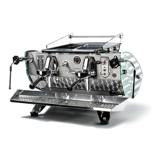
Special show model with touchpad operation for the left group and bastone operation for the right group. The Mirage Triplette is wider since it has an extra group in between the two groups shown here but its function is identical to a Duette. -
Page 5: Dimensions
79 cm 98 cm Approximate footprints of Mirage Duette (left) and Mirage Triplette (right). Black circles are rubber feet. Countertop feedthrough (dark grey circle; diameter 60 mm) is optimally positioned in light grey square. Note that steam wands will protrude a few centimetres left and right from machine. -
Page 6: Main Characteristics
22 and 40 cm (9” and 16”) behind the front feet (see machine side-view). The width of a Mirage (body without steam wand) Duette is 730 mm (28.7”), the width of a Triplette is 920 mm (36.2”). Ensure that this hole is not above the knock-box! Where 1 or 2 optional steam foot-pedals are used: There is a hole needed for the thin rubber tube(s) from under the machine to the foot pedal on the ground. -
Page 7: Abridged Machine Performance
Flow rate in the wide conduits of the Mirage’s thermo-siphon system is controlled by a flow restrictor (or jet). The restrictor is a fitting with a small opening which is either fixed or (optional) adjustable. - Page 8 WELCOME Figure W 2: Schematic hydraulics Mirage at idle. Sizes of restrictors may be different in your machine. Mirage technical manual page 7 of 65...
- Page 9 WELCOME Figure W 3. Schematic hydraulics Mirage when brewing. Sizes of restrictors may be different in your machine. Mirage technical manual page 8 of 65...
- Page 10 The expansion valve in the coffee water system, which is adjusted to 11-12 Bar at our workshop, in combination with a safety valve of 1.8 Bar on the steam boiler ensure that pressures inside the Mirage cannot exceed safety values.
-
Page 11: Notice
“Americanos”. All parts in the Mirage which spill water or steam in whatever circumstances are connected to the drain pipe on the back of the drip-tray. The group valves, expansion valve, pressure safety valve and anti-vacuum valve will thus not leak any water on your counter or the Mirage’s electronics or blow... -
Page 12: Water Quality
While too much mineral content will hasten damaging lime scale build-up inside your Mirage, an absence of minerals will give your espresso a flat taste while also harming the boilers inside the machine. As a rule of thumb, the amount of total dissolved solids (TDS) in your water should be 100-150 mg/l (=ppm). -
Page 13: Note On This Manual
Insanely Long Water FAQ, Originally Posted on alt.coffee. Note on this manual Work on the Mirage manual (touchpad version) is a continuing process. Photographs in the manual are taken in the shop from machines being built or from parts available, they range from 2012 to 2016. -
Page 14: Maintenance
“on”. In both cases there is a possibility that you touch a live wire. Danger We cannot be held responsible for damage and/or injuries resulting from actions performed on our machines by non-qualified personnel. Mirage technical manual page 13 of 65... -
Page 15: Handy Items While Performing Maintenance
O-ring. Two wooden blocks with approximate dimensions 15x5x20 cm (6x2x8 inch) to tilt the machine backwards for easier access to the bottom of the Mirage. Mirage technical manual page 14 of 65... - Page 16 Figure M 3. Temperature meter with sensor mounted in filter holder with adjustable flow and long tip temperature sensor. Filter holder with controlled outflow and quick response (QR) temperature sensor, separate QR- sensor and meter to check brewing temperature and hot water temperature. Mirage technical manual page 15 of 65...
-
Page 17: Remove Body Panels
2. Carefully pull aluminium side panel away from the machine, do not lose the rubber and stainless steel washer underneath the nuts. 3. When remounting, don’t forget the rubber and stainless steel washer and do not over tighten the nuts. Mirage technical manual page 16 of 65... - Page 18 4. When re-mounting, make sure that the lower cup warming tray does not scratch the back end of the machine. Put a little grease on the Allen bolts, do not over-tighten. 5. Replace upper cup warming tray. Mirage technical manual page 17 of 65...
- Page 19 Remove appropriate side panel first. Warning! It is essential to disconnect the Mirage from the power outlet before removing the upper side panels, especially the one on the left hand side. 1. Unscrew the 2.5 mm Allen bolts on the upper finishing strip a few turns.
-
Page 20: Boiler Temperature Vs Steam Power
"heat-on" control signal. °C water temperature 125 °C Graph M 1. Saturated steam pressure versus temperature (data from www.engineeringtoolbox.com). Note that most pressure gauges read overpressure (pressure as compared to atmospheric pressure). Mirage technical manual page 19 of 65... - Page 21 Changing the boiler temperature has little effect on coffee water temperature. If you want to change the temperature of the brewing process, you should alter the flow restrictor in the upper Banjo fitting (see next paragraph). Mirage technical manual page 20 of 65...
-
Page 22: Adjust Brew Temperature
1 full turn will result in a temperature change of 2-4 degrees Centigrade. When the knob is not firmly mounted on the needle, you can use a screw driver to adjust the needle. Mirage technical manual page 21 of 65... - Page 23 Use 19 mm spanner to make sure that housing of the adjustable restrictor is tight but do not over-tighten. b. Turn the knob clockwise or anti-clockwise to decrease resp. increase brew. 6. Replace cup-holder drip tray, do not mount bolts yet. Mirage technical manual page 22 of 65...
-
Page 24: Adjust Pump Pressure
When pump pressure exceeds approximately 12 Bar, the expansion valve will open. Increasing the pump pressure further will not result in higher coffee system pressure. Mirage technical manual page 23 of 65... -
Page 25: Check Water Treatment System
12 months to prevent bacterial growth. Note! Our machines do not show noticeable scaling for years provided that the water softener of these machines is regenerated as often as needed. Mirage technical manual page 24 of 65... -
Page 26: Anti-Vacuum Valve
Replacement anti-vacuum valve and copper O-ring ¼ Procedure 1. Turn Mirage “off”. 2. Open the steam valves, this will relieve the pressure in the hot water/steam boiler. 3. Remove cup warmer. 4. When all pressure is relieved, pull the black silicone (drain-) hose from the anti-vacuum valve (see Figure M 10). - Page 27 Figure M 10. Mirage Triplette without cup warmer showing location of level sensors, anti-vacuum valve, temperature probe, safety valve, mix block and hot water fitting. Mirage technical manual page 26 of 65...
-
Page 28: Grease Wands And Check Play Between Nut And Ball
6. Slide the spring and plunger back into the valve. 7. Slide the nut back over the wand, insert the red silicone O-ring (replace when necessary). 8. Replace the Teflon O-ring when necessary. Mirage technical manual page 27 of 65... - Page 29 10. Apply 2 drops of Loctite to the threads of the valve. Tighten nut with spanner, do not use excessive force. conical nut O-ring plunger and spring grease Figure M 12. Steam or hot water wand end with plunger removed. Grease parts as indicated. Mirage technical manual page 28 of 65...
-
Page 30: Check Tubing From Mix-Block To Fitting For Scale Build-Up
8. Mount tubing on the fitting on the mix-block, do not over-tighten. 9. Tighten nut on hot water fitting. 10. Dispense hot water and check for leakage, if necessary, tighten nuts a little more. 11. Replace cup warmer. Mirage technical manual page 29 of 65... -
Page 31: Check Restrictor In Mix-Block On Scale Build-Up
0.7 mm and is thus easily affected by any scale build up. While scale builds up, the temperature of the dispensed hot water will increase. Water mains of the Mirage should be shut for this operation, the machine does not have to cool down. Note! Do not drill the restrictor while it is installed in the mix-block. - Page 32 10. Remount the solenoid coil with spring washer and nut. The spring washer should be nearly flat but not over tightened as this will result in damage to the valve. 11. Remount cup warmer (put grease on Allen bolts). 12. Open water mains. Mirage technical manual page 31 of 65...
-
Page 33: Safety Valve On Steam Boiler
20 mm spanner, retain the fitting with a 20 mm spanner(see Figure M 14). Note! The valve is mounted with Loctite to ensure sealing, you may need a little extra torque to loosen it. 6. Clean inside threads of the fitting as well as possible. Mirage technical manual page 32 of 65... - Page 34 8. Turn mains switch to “2”, wait until pressure has built up. 9. Check valve and sealing for leakage. 10. Remount hose. 11. Mount cup warmer. Figure M 14. Use 2 spanners to remove the safety valve from the tube. Mirage technical manual page 33 of 65...
-
Page 35: Expansion Valve On Manifold
The expansion valve will release drops of water when pressure exceeds the set value, the released water is directed into the discharge. The expansion valve is mounted on the cold-water manifold on the left hand side of the Mirage and thus works on all groups simultaneously. - Page 36 11. Remount black silicone drain hose on expansion valve. 12. Remount side panel. Figure M 15. Showing expansion valve and way to make adjustments. Drain hose is removed from valve. Mirage technical manual page 35 of 65...
- Page 37 7. Turn outer part on expansion valve until approximately the same position as (6) above, then another 2 full turns. 8. Open water mains. 9. Continue with (4) in section “check expansion valve”. Mirage technical manual page 36 of 65...
-
Page 38: Rebuild Valves
6. Remove the two Allen bolts (5 mm), a spring will push the valve from its base (the base of the valve will remain on the Mirage). Be careful not to lose any parts. The Teflon O-ring will probably remain in the valve, pry out gently. - Page 39 Figure M 17. Exploded view of steam valve and assembly. The base of the valve will remain attached to the Mirage. Note position of longer Allen bolt on top side of assembled valve. On the Mirage, the longer Allen bolt is the lower one on the left hand side steam valve and the upper one on the right hand side steam valve (as seen from the Barista’s side).
-
Page 40: Clean Probes, Level And Safety
Two probes are mounted in the hot water/steam boiler. The probe with the orange wire checks the water safety level. Power to the heating elements in the Mirage is disconnected when water level is lower than this probe. The probe with the white wire checks the water level in the steam boiler for normal operation;... - Page 41 8. Connect the electrical wires to the probes: orange is safety level, white is operating level. 9. Switch Mirage “on”, the boiler may start to top up automatically. 10. Check for proper operation: a. no power to heating element until safety level is reached (pull orange wire from probe to check, the elements should be disengaged now) b.
-
Page 42: Replace All Solenoid Valves
MAINTENANCE MANUAL Replace all solenoid valves To be sure that the solenoid valves inside your Mirage keep operating properly, it is advised that you replace them every 5 years. The electrical coil outside, and spring and Viton sealing inside the valve are prone to wear and tear. - Page 43 Too much strain on the coil- tube will separate it from the valve. 7. Mount electrical plug on coil with rubber seal and screw. Mirage technical manual page 42 of 65...
- Page 44 10. Mount fittings on replacement valves with drop of Loctite, use new copper O-rings. Caution! The entrance to the valve is indicated by a little arrow pointing inwards, the fitting with particle screen and flow restrictor must be on this side. Mirage technical manual page 43 of 65...
- Page 45 Too much strain on the coil-tube will separate it from the valve. Mount and electrical plug with rubber seal on coil. Mirage technical manual page 44 of 65...
- Page 46 If the damage to the half-ball is not too severe, the tubing will seal, if it does not seal: replace tubing. 5. Remount body panels and cup warmer. Mirage technical manual page 45 of 65...
-
Page 47: Drain All Water When Freezing Is Possible
11. Open drain valve on steam/hot water boiler. 12. When water flow stops, tilt the Mirage by lifting the left side (e.g. by placing a block of wood under the front-left foot of the machine) to drain remaining water from the steam/hot water boiler until flow stops. - Page 48 (rather check for leakage next time the machine is filled and pressurised, then tighten when necessary). 26. Remount bottom panel. The discharge hose will probably remain loose when you want to transport the Mirage. Mirage technical manual page 47 of 65...
-
Page 49: Technical Information
ST25 temperature controller Figure T 1. Schematics of the 230VAC circuit in a Mirage Duette (3600W). NB: the control power from ST25 to SSR is 12VDC. Mirage technical manual page 48 of 65... -
Page 50: Electric Scheme Mirage 3-Phase: Duette High Power/Triplette
ST25 temperature controller Figure T 2. Schematics of the 230VAC circuit in the Mirage Duette high power (5200W) and Mirage Triplette (6400W). Wires on grey connector block are marked "I". "II" or "III" according to individual circuit. Compare to Figure T 5 and Figure T 6. NB: the control power from ST25 to SSR's is 12VDC. -
Page 51: Level Control And Water Meters
2 only Figure T 4. The 3x 3-way switch used in the Mirage Duette 1-phase. In position 1 power is fed onto the machine, but not onto the heating element. Only in position 2 is the element also connected to the power mains (phase via the SSR). -
Page 52: Mains Switch Duette High Power/Triplette
SSR’s) are in use. In position “1” connections are made between 1 and 11, 2 and 12, etc. In position “2” connections are made between 01 and 21, 02 and 22, etc. as well. Mirage technical manual page 51 of 65... -
Page 53: Triplette Connector Block: 3-Phase Or 1-Phase
In machines for most countries the mains cable is brown (phase), blue (neutral) and green/yellow (earth). Also shown is the USA/Canadian mains cable (split phase: 2-phase 115VAC with 180 degrees phase shift. Black is phase, white is counter-phase, green is earth.). Mirage technical manual page 52 of 65... -
Page 54: Problem Solving
PROBLEM SOLVING Problem solving Although we take the utmost care to include the best possible parts in the Mirage, some parts have been known to malfunction more often than others. Below we describe the most common electro- mechanical failures in the Mirage and the behaviour displayed by the machine when that part breaks down. - Page 55 When the transformer breaks down, the entire controller should be replaced. Replace controller Different versions of controllers are used in the Mirage which are not always compatible. When installing a new controller, make sure that you have the correct replacement. A new controller (the so- called LL√...
-
Page 56: Steam Boiler Temperature Controller
The steam boiler temperature controller is a Stork ST25 modified for Kees van der Westen espresso machines. The ST25 can function both as PID and as thermostat. In the Mirage it is used as a user- friendly, very precise thermostat. Fast response is obtained by measuring the temperature in the steam (instead of the water). - Page 57 Printed circuit board (PCB) inside the controller has shifted w.r.t. its casing, or switch on the PCB has bent out of reach of the push button. Check if PCB can be shifted back, otherwise replace controller. Mirage technical manual page 56 of 65...
-
Page 58: Solid State Relay
PROBLEM SOLVING Solid state relay The solid state relay (SSR, see Figure P 4) in the Mirage is a normally open electric relay without the moving parts found in an electro-mechanical relay. When a (small) control voltage is applied to the SSR, a LED illuminates which in turn switches on a photo sensitive diode. - Page 59 ST25 Figure P 5. Simplified heating circuits for Mirage Duette with two active heating spirals (above) and Mirage Triplette or Duette high power with three heating spirals. The heating spiral(s) connected to the failing SSR keep on heating, even when the indicator LED on the SSR is not lit.
- Page 60 EITHER: 1. Replace the failing SSR (see above). If you don’t have a replacement SSR available, you can still use the Mirage but it will operate using 2 of the 3 heating spirals. 2. Disconnect the failing SSR from the mains (connector no.2, the mains supply to the SSR), make sure that you isolate the disconnected wire properly.
- Page 61 5. Turn mains switch to “2”. 6. Check functioning of machine. 7. Remount side panel. When the machine has actually overheated, it must cool down to appr. 105°C before the overheat safety switch can be re-set. Mirage technical manual page 60 of 65...
-
Page 62: Heating Element
If only one spiral has a short circuit, you can rig your Mirage such that it will operate on the remaining 2 heating spirals until you can change the heating element. You must disconnect both leads of the failing spiral on the heating element itself since the short circuit will persist via the common neutral (the right hand side connectors). - Page 63 Figure P 7. Side view of heating element with mounting materials. The connectors pair up horizontally for each individual spiral. Shown here is a Teflon ring as seal, other sealing mechanisms exist on our machines (see Figure P 9 and Figure P 10). Mirage technical manual page 62 of 65...
- Page 64 (right) are bridged on the large grey connector block. The temperature sensor of the overheat safety switch is inserted in a tube in the centre of the heating element flange. Mirage technical manual page 63 of 65...
-
Page 65: Heating Element Seal
Figure P 10. Custom element flange by TRIAS must be sealed with EPDM O-ring (42x4.5mm) only as the flange has an integrated O-ring chamber. The TRIAS flange will NOT properly seal with a Teflon ring. Mirage technical manual page 64 of 65... -
Page 66: More Information On Our Website
Visit our website for latest versions of spare parts lists, (pre-) installation and user manuals, etc: http://www.keesvanderwesten.com/mirage-support.html Contact information Please supply machine details (model and number) and full contact information when seeking support or ordering parts. Kees van der Westen Espressonistic Works B.V. Van Elderenlaan 6 5581WJ WAALRE The Netherlands Telephone...
Need help?
Do you have a question about the Mirage and is the answer not in the manual?
Questions and answers