Toro Greensmaster e1021 Service Manual
Hide thumbs
Also See for Greensmaster e1021:
- Diagnostic manual (84 pages) ,
- Operator's manual (44 pages) ,
- Installation instructions (2 pages)
Chapters
Table of Contents

Related Manuals for Toro Greensmaster e1021


Summary of Contents for Toro Greensmaster e1021
- Page 1 Form No. 20246SL Rev A Greensmaster ® e1021/e1026 (Models 04831 and 04841) © 2021—The Toro® Company Original Instructions (EN) 8111 Lyndale Avenue South Contact us at www.Toro.com. Bloomington, MN 55420 All Rights Reserved...
- Page 2 Revision History Revision Date Description Initial issue. 06/2021 Revision History Page 2 Greensmaster ® e1021/e1026 20246SL Rev A...
- Page 3 Reader Comments The Toro Company Technical Assistance Center maintains a continuous effort to improve the quality and usefulness of its publications. To do this effectively, we encourage user feedback. Please comment on the completeness, accuracy, organization, usability, and readability of this manual by an e-mail servicemanuals@toro.com...
- Page 4 NOTES NOTES Page 4 Greensmaster ® e1021/e1026 20246SL Rev A...
- Page 5 Service Manual for reference. Additional copies of the Operator’s Manuals, Installation Instructions and Parts Catalogs are available at www.toro.com. The Toro Company reserves the right to change the product specifications or this publication without notice. DANGER This safety symbol means danger.
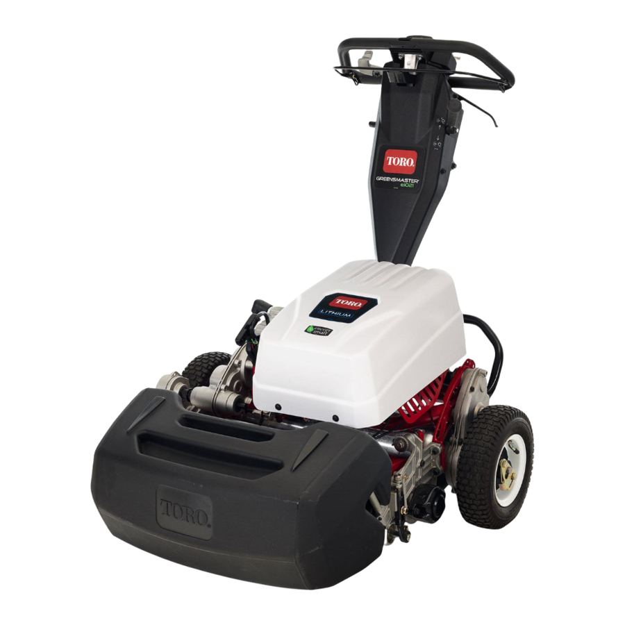
- Page 6 g340650 Figure 1 Model 04831 shown Preface Page 6 Greensmaster ® e1021/e1026 20246SL Rev A...
- Page 7 Service Procedure Icons The following icons appear throughout this Service Manual to bring attention to specific important details of a service procedure. Critical Process This icon is used to highlight: • installing safety equipment (shields, guards, seat belts, brakes and R.O.P.S. components) that may have been removed.
-
Page 8: Table Of Contents
Table of Contents Preface ........................ 5 Chapter 1: Safety .................... 1–1 Safety Instructions ..................1–2 Safety and Instructional Decals ..............1–5 Chapter 2: Specifications and Maintenance ............ 2–1 Specifications ....................2–2 Torque Specifications ................... 2–5 Shop Supplies .................... 2–11 Special Tools ....................2–13 Chapter 3: Troubleshooting ................ - Page 9 Chapter 1 Safety Table of Contents Safety Instructions ..........................1–2 Safety and Instructional Decals ......................1–5 Greensmaster ® e1021/e1026 Page 1–1 Safety 20246SL Rev A...
-
Page 10: Safety Instructions
Safety Instructions The Greensmaster e1021/e1026 machine is tested and certified by Toro for compliance with existing safety standards and specifications. Although hazard control and accident prevention are partially dependent upon the design and configuration of the machine, these factors are also dependent on the awareness, concern, and proper training of the personnel involved in the operation, transport, maintenance, and storage of the machine. - Page 11 – Use only Toro-specified lithium-ion battery packs designed for your machine. Do not mix battery of any brand or type in Toro products. – Use only the Toro-specified lithium-ion charger designed to charge your machine. Do not attempt to use any other battery charger.
- Page 12 – Do not work under a suspended load. – Ensure chock blocks are used on equipment that can move. – Use lifts or jacks and jack stands that are rated to support the total weight of the machine and any attachments. –...
-
Page 13: Safety And Instructional Decals
Numerous safety and instruction decals are affixed to the traction unit and cutting units of your Groundsmaster. If any decal becomes illegible or damaged, install a new decal. Decal part numbers are listed in your Parts Catalog. Order replacement decals from Authorized Toro Distributor. Greensmaster ®... - Page 14 Safety: Safety and Instructional Decals Page 1–6 Greensmaster ® e1021/e1026 20246SL Rev A...
- Page 15 Chapter 2 Specifications and Maintenance Table of Contents Specifications ............................2–2 Overall Dimensions..........................2–2 Traction and Reel Drive Systems ....................... 2–3 Controls, Wheels and Accessories ....................2–3 DPA Cutting Units ..........................2–3 Universal Groomer..........................2–4 Torque Specifications ........................... 2–5 Calculating the Torque Values When Using a Drive-Adapter Wrench ..........2–6 Identifying the Fastener........................
-
Page 16: Specifications
Specifications Overall Dimensions g340649 Figure 2 Specifications and Maintenance: Specifications Page 2–2 Greensmaster ® e1021/e1026 20246SL Rev A... -
Page 17: Traction And Reel Drive Systems
Traction and Reel Drive Systems Item Description Transmission Electric motor to transmission Transmission drive uses spur gears Traction Drive Transmission to traction drive uses a series of spur gears Differential Spur gear planetary differential Parking Brake Band style (at differential shaft drive) Traction Drum Dual aluminium, 19.1 cm (7.5 inch) diameter Cutting Reel Drive... -
Page 18: Universal Groomer
25 kg (55 lbs) 28.6 kg (63 lbs) 14 blade 26.3 kg (58 lbs) Options: Refer to the Cutting Unit Parts Catalog or contact your local Authorized Toro Distributor for available cutting unit options. Universal Groomer Item Description Grooming reel diameter 6 cm (2.375 inches) -
Page 19: Torque Specifications
Torque Specifications The recommended fastener torque values are listed in the following tables. For critical applications, as determined by Toro, either the recommended torque or a torque that is unique to the application is clearly identified and specified in this Service Manual. -
Page 20: Calculating The Torque Values When Using A Drive-Adapter Wrench
Calculating the Torque Values When Using a Drive-Adapter Wrench g205924 Figure 3 Torque Conversion Factor = A / B Torque wrench A (effective length of torque wrench) Drive-adapter wrench (crowsfoot) B (effective length of torque wrench and drive-adapter wrench) Using a drive-adapter wrench (e.g., crowfoot wrench) in any position other than 90°... -
Page 21: Identifying The Fastener
Toro recommends replacing fasteners with a locking feature once they have been removed because the effectiveness of the locking feature diminishes with each reuse. If it is necessary to reuse a fastener with a locking feature; apply a thread locking compound (Loctite for example) to the fastener during installation. -
Page 22: Standard Torque For Dry, Zinc Plated, And Steel Fasteners (Inch Series)
Standard Torque for Dry, Zinc Plated, and Steel Fasteners (Inch Series) Thread Size Grade 1, 5 SAE Grade 1 Bolts, Screws, SAE Grade 5 Bolts, Screws, SAE Grade 8 Bolts, Screws, and 8 with Studs, and Sems with Studs, and Sems with Studs, and Sems with Thin Height Regular Height Nuts... -
Page 23: Standard Torque For Dry, Zinc Plated, And Steel Fasteners (Metric Fasteners)
Standard Torque for Dry, Zinc Plated, and Steel Fasteners (Metric Fasteners) Class 8.8 Bolts, Screws, and Class 10.9 Bolts, Screws, and Thread Size Studs with Regular Height Nuts Studs with Regular Height Nuts (Class 8 or Stronger Nuts) (Class 10 or Stronger Nuts) M5 X 0.8 57 ±... -
Page 24: Other Torque Specifications
Other Torque Specifications SAE Grade 8 Steel Set Screws Recommended Torque Thread Size Square Head Hex Socket 1/4 - 20 UNC 140 ± 20 in-lb 73 ± 12 in-lb 5/16 - 18 UNC 215 ± 35 in-lb 145 ± 20 in-lb 3/8 - 16 UNC 35 ±... -
Page 25: Shop Supplies
Shop Supplies The procedures found in this Service Manual may recommend the use of commonly used shop supplies (lubricants, sealants and adhesives). A symbol denoting the use of a shop supply may appear in figures that support a procedure. Always refer to the written procedure for specific information regarding the type and the application of a shop supply. - Page 26 GASKET COMPOUND Used to create a seal between mating parts. Gasket compounds may be used with or without the presence of a pre-formed gasket. Gasket compounds may be solvent or silicone based, and cure when exposed to air or designed to cure in an air-less environment (anaerobic). Most gasket compounds are designed to be applied to clean surfaces free of oil, chemical residue and previously used gaskets or gasket compounds.
-
Page 27: Special Tools
This excess current can damage the circuits that are not designed to carry it. Dielectric Gel Toro Part No. 107-0342 Use the dielectric gel to prevent corrosion of unsealed connection terminals. To ensure complete coating of the... - Page 28 Cutting Performance Paper Toro Part No. 125–5610 (300 strips) Cutting performance paper is used to test the cutting reel performance after adjusting the reel to bedknife clearance. Backlapping Brush Assembly K Line Part No.
- Page 29 Reel Thread Repair Taps 15/16–16 Right-Hand Thread – Toro Part No. 137–0926 15/16–16 Left-Hand Thread – Toro Part No. 137–0927 Use to clean or repair the internal threads of cutting unit reels. Angle Indicator and Magnetic Mount Angle Indicator: Toro Part No. 131–6828 Magnetic Mount: Toro Part No.
- Page 30 Bedknife Screw Tool (continued) K-Line Part No. TOR510880A This screwdriver-type bit is made to fit Toro bedknife attaching screws. Use this bit with a torque wrench to secure the bedknife to the bedbar. IMPORTANT Important: To prevent damage to the bedbar, DO NOT use an air or manual impact wrench with this tool.
- Page 31 This tool should be used with the Toro Guide to Evaluation Reel Mower Performance and Using the Turf Evaluator (Toro part no. 97931SL) available from your local authorized Toro Distributor.
- Page 32 Lithium-Ion Battery Shipping Kit Toro Part No. 137–9650 Use the original packaging or the battery shipping kit and a certified carrier to ship one of the lithium-ion batteries. The kit includes the appropriate carton, packing, labels, and instructions necessary to confirm to current lithium-ion battery shipping regulations in the USA.
- Page 33 Chapter 3 Troubleshooting Table of Contents GEARS – The Systematic Approach to Defining, Diagnosing and Solving Problems ......3–2 Gather Information ..........................3–2 Evaluate Potential Causes ......................... 3–2 Assess Performance.......................... 3–2 Repair ..............................3–2 Solution Confirmation......................... 3–2 Operator Advisories..........................3–3 Machine Faults ............................
-
Page 34: Gears - The Systematic Approach To Defining, Diagnosing And Solving Problems
GEARS – The Systematic Approach to Defining, Diagnosing and Solving Problems Gather Information • Information reported by the customer • Information observed by you • Establish the what, where and when of the issue Evaluate Potential Causes • Consider possible causes of the problem to develop a hypothesis •... -
Page 35: Operator Advisories
Operator Advisories g340684 Figure 9 Advisory name Advisory identification Operator advisories are automatically displayed by the InfoCenter when a machine function requires additional action (Figure 9). An advisory will not be logged into the fault log. The InfoCenter advisories include the following: #201 (System Shutdown): This advisory notifies the operator that the machine is shutting down. - Page 36 #212 (Motor Disabled): The motor disabled advisory will identify that electric motor operation was stopped by the controller. A fault should have been generated that will provide additional information as to cause of the issue. #213 (Disengage Traction): This advisory notifies the operator that the bail lever is engaged and needs to be released before operation can be continued.
-
Page 37: Machine Faults
Machine Faults Faults --32.6 Ago Clear System Faults g340685 Figure 10 Left/right button Fault items Down button Fault menu Menu/back button The faults screen (Figure 10) will list all the machine electrical faults that have occurred since the faults were last cleared from the InfoCenter. The faults will be identified by a number and when the fault occurred. - Page 38 Motor will likely need replacing if the fault continues. Software One of the devices in the Use Toro DIAG to reprogram the Incompatible system has software that is machine. incompatible. Key Stuck Master The battery has detected Verify the battery is charged.
- Page 39 Fault Table (continued) Fault Fault Title Additional Controller Fault Condition/Circuit Service Actions Number Affected Description Notes Software Master The software has detected Try rebooting machine, Error an issue with reading the disconnect and reconnect the battery, look for short circuits throttle sensor.
-
Page 40: Battery Charger Error And Fault Codes
Ensure that the battery is in good condition. Code E-0-0-4 Lithium-ion battery controller (BMS) or Contact an Authorized Toro Distributor battery fault detected for assistance. Code E-0-0-7 Battery amp hour limit exceeded Check all battery cable connections for corrosion or damage. -
Page 41: Electrical System Problems
Electrical System Problems CAUTION Remove all the jewelry, especially rings and watches, before doing any electrical troubleshooting or testing. For the effective troubleshooting and repairs, you must have a good understanding of the electrical circuits and components that are used on this machine;... - Page 42 Machine is Inoperative and InfoCenter Power Light Indicates That a Fault Has Occurred Possible Causes Correction System fault has been detected by controller. Use the Faults screen information in the InfoCenter section of this chapter to help identify source of problem. An electrical fault occurred that can be reset Attempt to restart the machine to see if the by the controller.
-
Page 43: Aftercut Appearance
Note: For additional information regarding cutting unit troubleshooting, a number of Reel Mower and Aftercut Appearance General Training Books can be found on the Service Reference Set available from your Authorized Toro Distributor. Factors That Can Affect Quality of Cut... -
Page 44: Factors Affecting Grooming
Factors Affecting Grooming There are a number of factors that can affect the performance of grooming. These factors vary for different golf courses and from green to green. It is important to inspect the turf frequently and vary the grooming practice with turf needs. -
Page 45: Grooming Reel Mechanical Problems
Grooming Reel Mechanical Problems Problem Possible Causes Correction Groomer not engaged. Groomer drive gears are worn Inspect groomer drive or damaged. assembly and replace damaged drive components. The turf is damaged or has The groomer is set too Refer to groomer Installation uneven grooming. - Page 46 Troubleshooting: Battery Charger Error and Fault Codes Page 3–14 Greensmaster ® e1021/e1026 20246SL Rev A...
- Page 47 Chapter 4 Traction and Reel Drive Systems Table of Contents General Information ..........................4–2 Disengaging The Drum Drive From Transmission................4–2 Adjustments ............................4–3 Adjusting the Reel Drive Belt......................4–3 Service and Repairs ..........................4–5 Reel Drive Belt ........................... 4–5 Reel Drive Assembly..........................
-
Page 48: General Information
General Information The Operator’s Manual provides information regarding the operation, general maintenance, and maintenance intervals for your machine. Refer to the Operator’s Manual for additional information when servicing the machine. Disengaging The Drum Drive From Transmission g335307 Figure 11 Transmission gear box assembly Traction engage/disengage lever The traction drum is driven by series of spur gears inside the transmission gear box assembly. -
Page 49: Adjustments
Adjustments Adjusting the Reel Drive Belt g258535 Figure 12 Reel drive box assembly Bolt Socket head screw (3 each) Reel belt Gasket Idler arm Reel drive cover 1. Park the machine on a level surface. Disconnect the battery pack; refer to Connecting the Lithium Battery Pack (page 5–3). - Page 50 Adjusting the Reel Drive Belt (continued) 4. Adjust belt tension (2) as follows: A. Loosen the bolt (4) and rotate the idler arm (3) to release the tension on the reel drive belt (2). B. Pivot the idler arm (3) clockwise against the backside of the belt and apply a torque 3.9 to 4.5 N∙m (35 to 40 in-lb) to internal hex socket on the idler arm (3).
-
Page 51: Service And Repairs
Service and Repairs Reel Drive Belt g258535 Figure 13 Reel drive box assembly Bolt Socket head screw (3 each) Reel belt Gasket Idler arm Reel drive cover The greensmaster machines use a positive drive belt on the right side of the machine to operate the cutting unit. - Page 52 Removing the Reel Drive Belt (continued) 3. Remove and inspect the reel drive gasket (5) from the reel drive assembly (1). Discard the reel drive gasket (5), if damaged. 4. Loosen the bolt (4) and rotate the idler arm (3) to release the tension on the reel drive belt (2).
-
Page 53: Reel Drive Assembly
Reel Drive Assembly g361728 Figure 14 Screw (2 each) V-ring seal RH side plate Spacer (2 each) Reel drive assembly Transmission drive shaft Washer (2 each) Spacer Spring washer (2 each) Telescopic coupler Removing the Reel Drive Assembly Note: Refer to Figure 14 during this procedure. - Page 54 Disassembling the Reel Drive Assembly g258688 Figure 15 Reel shaft-driven Socket head screw Reel shaft-driver Reel drive housing O-ring Socket head screw (3 each) Pivot sleeve Expansion plug O-ring Reel drive gasket Reel drive cover Bolt Ball bearing (2 each) Reel pulley - 22 tooth Lock nut (2 each) Internal snap ring...
- Page 55 Disassembling the Reel Drive Assembly (continued) 9. Remove the retaining ring (6) from the reel drive housing (22). 10. Slide the reel shaft-driven from the bearings. 11. Use a press to remove the 2 ball bearings (5) and reel shaft-driven (1) from the reel drive housing (22).
- Page 56 Assembling the Reel Drive Assembly (continued) 19. Install the bolt (28), washer (27) and nut (25) to the idler arm (26) and reel drive housing (22). Do not tighten the bolt (28). g258764 Figure 16 Press flush 20. If removed, install the expansion plug (13) to the reel drive cover (14) and press flush to outer surface (refer to Figure 16) of the reel drive cover.
-
Page 57: Drum Drive Gear Box Assembly
Drum Drive Gear Box Assembly g340911 Figure 17 Transmission gear box assembly Drive tube Splined coupler Traction drum Frame assembly Truss screw Shoulder bolt (3 each) Shoulder bolt LH hex shaft RH hex shaft Drum drive gear box assembly Washer Removing the Drum Drive Gear Box Assembly Note: Refer to Figure 17... - Page 58 Removing the Drum Drive Gear Box Assembly (continued) 4. Remove the shoulder bolt (8) that secures the RH drum drive gear box assembly (5) to the frame assembly (7). 5. Remove the 3 shoulder bolts (3) that secures the RH drum drive gear box assembly (5) to the traction drum (2).
- Page 59 Disassembling the Drum Drive Gear Box Assembly g258844 Figure 18 Oil seal Drum drive housing Washer Drum drive cover Retaining ring Outer drum hub Socket head screw (5 each) Oil seal V-ring seal Plug (2 each) Retaining ring Drum drive shaft Flange nut O-ring Ball bearing (2 each)
- Page 60 Disassembling the Drum Drive Gear Box Assembly (continued) 5. Remove the nut (12) that secures the spur gear (11) to the drum drive shaft (5). Slide and remove the spur gear (11) from the drum drive shaft (5). Locate and retrieve the key (30) from the drum drive shaft (5). 6.
- Page 61 Assembling the Drum Drive Gear Box Assembly g263151 Figure 19 1. Install the ball bearings (23), wave washer (24) and spur gear (21) to the drum drive housing (25). Note: The outer diameter and inner diameter of the ball bearings (23) must be slip fit.
- Page 62 Assembling the Drum Drive Gear Box Assembly (continued) 12. Install the drum drive cover (14) to the drum drive housing (25) and secure with 5 socket head screws (15). Torque tighten the socket head screws to 1.7 to 4.5 N∙m (15 to 40 in-lb). Use an alternation pattern and torque tighten the socket head screws to 9.6 to 10.7 N∙m (85 to 95 in-lb).
-
Page 63: Drum Assembly
Drum Assembly g340911 Figure 20 Transmission gear box assembly Drive tube Splined coupler Traction drum Frame assembly Truss screw Shoulder bolt (3 each) Shoulder bolt LH hex shaft RH hex shaft Drum drive gear box assembly Washer Removing the Drum Assembly Note: Refer to Figure 20 during this procedure. - Page 64 Disassembling the Drum Drive Assembly g258879 Figure 21 Traction drum (2 each) Drum spindle Spacer Bolt (8 each) Seal (2 each) Drum hub Lock washer (8 each) Ball bearing (2 each) Shoulder bolt (6 each) Drum hub plate (2 each) Spacer Lock nut Note: Refer to...
- Page 65 Assembling the Drum Drive Assembly g258942 Figure 22 Drum hub Spacer Ball bearing (2 each) Spacer Drum spindle Lock nut Seal (2 each) Note: The seal side of each bearing (item 7 in Figure 22) should face inside of the drum hub; refer to Figure 1.
- Page 66 Installing the Drum Drive Assembly 1. Park the machine on a level surface. Disconnect the battery pack; refer to Connecting the Lithium Battery Pack (page 5–3). 2. Position the LH and RH drum drive gear box assembly (item 5 in Figure and traction drum (2) onto the frame assembly (7).
-
Page 67: Transmission Gear Box Assembly
Transmission Gear Box Assembly g341006 Figure 23 Truss screw (2 each) Jam nut Splined coupler (4 each) Bolt (2 each) Electric motor Washer (2 each) Transmission gear box assembly O-ring Lock nut (2 each) Socket head screw (4 each) Reel drive coupling Drive shaft Motor adaptor Drive tube... - Page 68 Removing the Transmission Gear Box Assembly Note: Refer to Figure 23 during this procedure. 1. Park the machine on a level surface. Disconnect the battery pack; refer to Connecting the Lithium Battery Pack (page 5–3). 2. Disconnect the brake cable; refer to Removing the Brake Cable (page 6–4).
- Page 69 Disassembling the Transmission Gear Box Assembly g339791 Figure 24 Retaining ring Grease seal Brake mount pin Spacer bushing Ball bearing (2 each) Transmission gasket O-ring Spacer Transmission cover Straight bushing (2 each) Oil seal (2 each) Socket head screw (12 each) Retaining ring (2 each) Oil seal Ball bearing (2 each)
- Page 70 Disassembling the Transmission Gear Box Assembly (continued) 3. Remove the oil seal (6), retaining ring (5) from the transmission cover (23). Use a press to remove the ball bearing (25) from the transmission cover (23). Discard the oil seals and ball bearing. g339790 Figure 25 External retaining ring...
- Page 71 Disassembling the Transmission Gear Box Assembly (continued) 9. If necessary, disassemble the differential assembly (14); refer to Disassembling the Differential Assembly (page 4–33). 10. Remove the bolt (25) that secures the cable brake lever (24) onto the brake lever (19). Slide and remove the cable brake lever (24) and external retaining ring (1) from the brake lever (19).
- Page 72 Disassembling the Transmission Gear Box Assembly (continued) g339789 Figure 26 Short bearing pin Flange nut (2 each) Reel clutch shoe O-ring Wave spring Reel clutch actuator Long bearing pin Ball bearing (2 each) Spur gear Thin lock nut Bearing spacer (2 each) Retaining ring (2 each) Retaining ring (4 each) Reel drive shaft...
- Page 73 Disassembling the Transmission Gear Box Assembly (continued) C. Slide and remove the slider spur gear (14) from the reel drive shaft (12). D. Remove the two key squares (13) from the reel drive shaft (12). 16. Remove the nut (8) and long bearing pin (3) that secures the spur gear assembly (7) to the transmission housing assembly (20).
- Page 74 Assembling the Transmission Gear Box Assembly 1. Use a press to install the spacer (item 13 in Figure 24) and new ball bearings (12 and 25) into the transmission housing (26). 2. Install the retaining ring (item 5 in Figure 24) into the transmission housing (26).
- Page 75 Assembling the Transmission Gear Box Assembly (continued) 19. Apply a coat of grease to the O-ring (item 2 in Figure 26) and slide the O-ring onto the long bearing pin (3). Install the spur gear assembly (7) and bearing spacer (4) onto the transmission housing assembly (20) and secure with the long bearing pin (3) and nut (8).
- Page 76 Assembling the Transmission Gear Box Assembly (continued) 37. Insert the wave washer (item 3 in Figure 25) and neutral spur gear assembly (5) into the transmission housing assembly (23). Make sure that the traction selector shaft (item 19 in Figure 24) is engaged in shift selection neutral spur gear (item 5 in Figure...
- Page 77 Installing the Transmission Gear Box Assembly Note: Refer to Figure 23 during this procedure. Install the electric motor (22) and motor adaptor (18) onto the transmission gear box assembly (6) and secure with the two socket head screws (19). 2. Position the transmission gear box assembly (10) onto the frame assembly and secure with 2 bolts (9) and a socket head screw (19).
-
Page 78: Differential Assembly
Differential Assembly g339790 Figure 27 External retaining ring O-ring (2 each) Brake lever Pipe plug Retaining ring (2 each) O-ring Wave washer Flange bearing (2 each) Brake clevis pin Ball bearing (2 each) Ball bearing (2 each) Flat wire spring Neutral spur gear Differential assembly Transmission housing assembly... - Page 79 Disassembling the Differential Assembly g259978 Figure 28 Differential housing (2 each) Differential spur gear (6 each) Socket head screw (6 each) Differential pin (6 each) Differential gear 1. Remove the 6 socket head screws (item 5 in Figure 28) that secures the differential housing assembly (1) to the differential gear (4).
- Page 80 Assembling the Differential Assembly 1. Place the differential housings (1) on the work bench. 2. Insert the 3 differential pins (2) in each differential housing. g260016 Figure 29 Differential spur gears with shoulder up Press flush 3. The differential pins (2) must be inserted in alternate holes of the differential housing (1) and ensure that the differential pins (2) are flush to the surface of the differential housing;...
-
Page 81: Chapter 5: Electrical System
Electrical System Operation ........................5–4 Battery Charging ..........................5–4 Start Process ............................. 5–5 Run Process ............................5–5 CAN-bus Communications......................... 5–6 Toro Electronic Controller (TEC) ......................5–7 Lithium-Ion Battery Controller (BMS) ....................5–8 InfoCenter Display ........................... 5–10 Adjustments............................5–20 Traction Bail Proximity Sensor ......................5–20 Testing the Electrical Components....................... -
Page 82: General Information
General Information The Greensmaster e1021 and e1026 machines uses a 48 VDC electrical system that is an isolated circuit. The machine frame is not used for any ground connections. After performing any repair on the machine electrical components, ensure that the wiring is routed and secured so as to prevent abrasion or contact with moving machine parts. -
Page 83: Connecting The Lithium Battery Pack
Connecting the Lithium Battery Pack WARNING Battery terminals, battery cables, or metal tools could short against metal components causing sparks. Sparks can cause the battery damage and high heat, resulting in personal injury. • When removing or installing the battery, do not allow the battery terminals or battery cables to touch any metal parts of the machine. -
Page 84: Electrical System Operation
Electrical System Operation The Greensmaster machines uses a 48 VDC lithium-ion battery pack to supply electrical power to the Toro electronic controller (TEC), an electric motor, and a main contactor. Circuit protection for this 48 VDC system includes 3 fuses that reside in the wire harness fuse block. -
Page 85: Start Process
Start Process When the key switch is turned to the START position, the machine electrical system goes through a wake-up process. The contactor in the battery pack should click as it is energized followed by the main contactor being energized (audible click). -
Page 86: Can-Bus Communications
The Toro DIAG electronic control diagnostics service system is available to Authorized Toro Distributors to support machine fault diagnosis and maintenance services of the machine electrical control devices. The Toro DIAG connector is located inside the upper cover assembly; refer to... -
Page 87: Toro Electronic Controller (Tec)
Figure 32 Samsung SDI controller Lithium battery pack The Greensmaster machine use a Toro Electronic Controller (TEC) to manage the machine electrical functions. The controller is a microprocessor controlled device that senses the condition of various switches (inputs) and directs electrical power to control the appropriate machine functions (outputs) based on the inputs. -
Page 88: Lithium-Ion Battery Controller (Bms)
Lithium-Ion Battery Controller (BMS) g338267 Figure 33 Lithium-ion battery controller The machine uses a Lithium-ion battery controller or Battery Management System (BMS) to manage the lithium-ion batteries. The lithium-ion battery communicate with the BMS through a sub-net via the battery interface harness. The battery interface harness includes a 4-pin connector at the battery and a 9-pin connector at the BMS. - Page 89 Opening the controller case may result in personal injury and property damage. Note: If the Lithium-Ion Battery Controller is replaced for any reason, the machine software must be updated; contact an Authorized Toro Distributor for assistance. Greensmaster ®...
-
Page 90: Infocenter Display
Figure 34 Handle InfoCenter display The InfoCenter display used on your Greensmaster e1021/e1026 is a LCD device that is located on the handle console (Figure 34). The InfoCenter provides information to the operator during the operation of the machine, provides electrical system diagnostic assistance for the technicians, and allows inputs for the adjustable machine settings. - Page 91 AFTER SECONDS MAIN INFORMATION SCREEN g339628 Figure 35 Greensmaster ® e1021/e1026 Page 5–11 Electrical System: Electrical System Operation 20246SL Rev A...
- Page 92 Splash Screen g339634 Figure 36 Fault indicator Down button Hour meter Menu/back button Left/right button When the key switch is initially turned to the RUN or START position, the fault indicator illuminates for a few seconds to verify indicator operation and the InfoCenter splash screen appears (Figure 36).
- Page 93 Main Information Screen (continued) The InfoCenter main information screen (Figure 37) is displayed after the initial splash screen has been displayed for 5 seconds. The main information screen is the default screen as it will be displayed during normal machine operation. The main information screen provides the following information to the operator: •...
- Page 94 Operator Advisories g339631 Figure 39 Advisory name Advisory identification Operator advisories are automatically displayed by the InfoCenter when a machine function requires additional action (Figure 39). An advisory will not be logged into the fault log. (Refer to Operator Advisories (page 3–3)).
- Page 95 Main Menu Screen (continued) • Settings • About Press the down button (as indicated by the at the bottom of the screen) to highlight the desired menu screen, then press the left/right button (as indicated by the at the bottom of the screen) to enter the highlighted menu screen. To return to the main information screen from the main menu screen, press the menu/back button (as indicated by the at the bottom of the screen).
- Page 96 Service Screen Hours: 132.4 Hours Power Use: 29 Watts Battery Charge g339632 Figure 42 Left/right button Service items Down button Service menu Menu/back button The service screen (Figure 42) contains the following machine information: • Hours (hours that the key switch has been in the ON position) •...
- Page 97 Diagnostics Screen agnostics art: Traction: g339626 Figure 43 Left/right button Diagnostics items Down button Diagnostics menu Menu/back button The diagnostics screen (Figure 43) lists the various states of the machine electrical components. The diagnostics screen should be used to check the operation of the machine switches and controls.
- Page 98 Diagnostics Screen (continued) • 5V Supply indicates the supplied voltage available for the 5 VDC circuit. The 5V Supply should typically be slightly higher than 5.0 VDC. • CAN identifies whether the machine communication bus status is normal or not. •...
- Page 99 About Screen About XXXXX 400000000 S/W Rev: g341573 Figure 45 Left/right button About items Down button About menu Menu/back button The about screen (Figure 45) identifies the machine model number, serial number, and TEC software revision. To return to the main menu screen from the about screen, press the menu/back button (as indicated by the at the bottom of the screen).
-
Page 100: Adjustments
Adjustments Traction Bail Proximity Sensor g349622 Figure 46 Jam nuts Clutch bail link Proximity sensor Adjusting the Traction Bail Proximity Sensor 1. Park the machine on a level surface. Ensure that the key switch is in OFF position and the traction control is in NEUTRAL. 2. -
Page 101: Testing The Electrical Components
Testing the Electrical Components Whenever possible, check the component circuit operation with the InfoCenter display on the console. With the key switch in the RUN position, use the InfoCenter diagnostics menu to ensure that the component state changes as the component is toggled. This quick check identifies that the component and circuit wiring are working as designed. -
Page 102: Fuses
Figure 48 to identify each individual fuse and its correct amperage. The fuses for the Greensmaster e1021/e1026 machines have the following functions: Fuse F1-1 (30 A): Protects main power supply circuits. Fuse F1-2 (3 A): Protects logic power supply circuits. - Page 103 Testing the Fuse 1. Access the fuse block as described above. 2. Carefully remove the fuse from the fuse block for testing. 3. The fuse should have continuity between the fuse terminals. IMPORTANT The e1021/e1026 machine uses special fuses that are rated for 80 V.
-
Page 104: Can Bus
2. Disconnect the battery pack; refer to Connecting the Lithium Battery Pack (page 5–3). 3. The Toro DIAG connector is located inside the upper cover assembly; refer Figure Electrical System: Testing the Electrical Components Page 5–24 Greensmaster ®... - Page 105 4. Refer to CAN-bus Terminator Resistor (page 5–39) and/or see electrical schematic and wire harness drawing in Appendix A (page A–1). If necessary, contact an Authorized Toro Distributor for assistance. Greensmaster ® e1021/e1026 Page 5–25 Electrical System: Testing the Electrical Components...
-
Page 106: Toro Electronic Controller (Tec)
Figure 51 Samsung SDI controller Lithium battery pack The Greensmaster machine use a Toro Electronic Controller (TEC) to manage the machine electrical functions. The controller is a microprocessor controlled device that senses the condition of various switches (inputs) and directs electrical power to control the appropriate machine functions (outputs) based on the inputs. - Page 107 Toro Electronic Controller (TEC) (continued) g338695 Figure 52 The diagram in Figure 52 depicts the connection terminal functions of the TEC. Two wire harness connectors attach to the controller with each of the connectors including 12 pins. The connector pins are listed in the diagram.
-
Page 108: Lithium-Ion Battery Controller (Bms)
The BMS is attached to the battery mount inside the battery cover. Note: If the Lithium–Ion Battery Controller is replaced for any reason, the machine software must be updated; contact an Authorized Toro Distributor for assistance. Testing the Lithium-Ion Battery Controller... - Page 109 Testing the Lithium-Ion Battery Controller (continued) g338794 Figure 55 Lithium-Ion battery controller B- terminal Positive (+) terminal Negative (–) terminal B+ terminal COM terminal M-S terminal Although there is no method to test the solid state circuitry built into the controller directly, some aspects of the lithium-ion battery controller operation can be tested as follows;...
-
Page 110: Electric Motor
Note: If the electric motor is replaced for any reason, the machine software must be updated; contact an Authorized Toro Distributor for assistance. Testing the Electric Motor 1. Park the machine on a level surface and make sure that the clutch bail in the NEUTRAL position. -
Page 111: Key Switch
Key Switch g338795 Figure 57 Screw (4 each) InfoCenter mount InfoCenter display Key switch Handle The key switch allows the machine operation to be turned on and off. The key switch has 3 positions: OFF, RUN, and START. This switch is 1 of the several inputs for the TEC and is located on the InfoCenter mount (Figure 57). - Page 112 Testing the Key Switch (continued) g190999 Figure 58 5. With the use of a multimeter (ohms setting), test the switch functions to determine if continuity exists between the various terminals for each switch position. The switch terminals are marked as shown in Figure 58.
-
Page 113: Throttle Potentiometer And Clutch Bail Potentiometer
Throttle Potentiometer and Clutch Bail Potentiometer g337125 Figure 59 Screw (4 each) Spacer (2 each) Extension spring InfoCenter display Control bail lever Spring tab Clevis pin Spacer (2 each) InfoCenter mount Lock nut Screw (2 each) Key switch Lock Throttle potentiometer sensor Bail catch fork Clutch bail potentiometer sensor Control bail lever... - Page 114 Checking the Operation of Throttle and Clutch Bail Potentiometers Check the operation of throttle and clutch bail potentiometers with the InfoCenter. With the key switch in the RUN position and the InfoCenter in the diagnostics menu, choose the Throttle and ensure that the displayed voltage changes as the speed wheel is rotated.
- Page 115 Testing the Throttle and Clutch Bail Potentiometers (continued) 6. After you complete the testing, secure the potentiometers to the machine (Figure 59). Secure the wire harness connector to the potentiometer. Secure the handle cover to the handle. Note: When re-installing the potentiometers, a minimum voltage reading of 0.5V for proper function is required.
-
Page 116: Main Contactor
Figure 61 Contactor Bolt (2 each) The Greensmaster e1021/e1026 machines use the main contactor to connect the lithium battery pack and the electric motor. The contactor is energized by the TEC. The contactor is attached to the battery mount under the battery cover; refer... - Page 117 Testing the Main Contactor (continued) g202780 Figure 62 Main contact post Coil post 4. Ensure that the battery pack is disconnected. Use a multimeter to measure the resistance across the contactor posts as follows (Figure 62). A. Resistance across the main contact posts should be infinite ohms. B.
- Page 118 Testing the Main Contactor (continued) g339028 Figure 63 Main contactor Coil post Main contact post 6. Use a multimeter to measure the voltage across the main contactor posts as follows: A. Position the rubber boots away from the main contactor posts to get access to the posts with multimeter probes (Figure 63).
-
Page 119: Can-Bus Terminator Resistor
Figure 64 The system communication between the electrical components on the Greensmaster e1021/e1026 machines are accomplished on a CAN-bus communication system. The 2 specially designed, twisted cables form the bus for the networks used on the e1021/e1026. These wires provide the data pathways between the machine components. -
Page 120: Relay
Relay g339075 Figure 65 Relay Washer Bolt The relay used on the e1021/e1026 machine is 4 terminal 48 V relay and located inside the battery cover and next to TEC controller; refer to Figure Testing the Relay 1. Park the machine on a level surface and make sure that the clutch bail in the NEUTRAL position. - Page 121 Testing the Relay (continued) 5. Using a multimeter (ohms setting), measure the coil resistance between terminals 85 and 86. The resistance should be from 990 to 1210 ohms. 6. Verify infinite resistance (no continuity) exists between terminals 30 and 87. 7.
-
Page 122: Service And Repairs
Service and Repairs Electric Motor g339147 Figure 67 Frame assembly Motor adaptor Transmission gear box assembly Socket head screw (3 each) Electric motor Socket head screw (4 each) Closed cell foam seal Note: A damaged electric motor assembly may cause a #6, #7, #8, #9, or #10 fault to be generated and displayed on the InfoCenter display. - Page 123 Removing the Electric Motor (continued) 5. Remove the 4 socket-head screws (item 3 in Figure 67) that secure the electric motor to the motor adaptor (4). 6. Carefully slide the electric motor from the transmission, and remove the motor from the machine. 7.
-
Page 124: Servicing The Electric Motor
Servicing the Electric Motor g293229 Figure 68 Cap screw (6 each) Bearing Motor cover O-ring O-ring Housing assembly Wave washer Lip seal Bearing O-ring Rotor Note: If the motor housing, controller, or cable damage occurs, the electric motor replacement is necessary. These components are not available separately. Note: If problems with electric motor exist, an advisory or fault may be identified on the InfoCenter display. - Page 125 Motor rotor tool shaft Motor rotor tool base plate 4. Secure the base plate of the motor rotor tool (Toro part number 139–8420) to the housing with four M6 – 1.0 X 50 cap screws. 5. Install the rotor tool shaft into the base plate and turn it in against the rotor shaft.
- Page 126 Assembling the Electric Motor (continued) 4. Lubricate new O-rings with dielectric lubricant and install the O-rings into the grooves in the motor cover. Place the wave washer in the cover bearing bore and fit the rotor assembly into the cover. 5.
-
Page 127: Lithium-Ion Battery Controller (Bms)
Lithium-Ion Battery Controller (BMS) g349591 Figure 70 Bolt (4 each) Positive (+) battery cables Washer (4 each) Negative (-) battery cables Lithium-ion battery controller Nut (4 each) Removing and Installing Lithium-Ion Battery Controller (BMS) CAUTION To prevent accidentally shorting disconnected battery cables across other components or tools, insulate the battery cable terminals with 76 mm (3 inch) lengths of 1/2 inch internal diameter rubber hose immediately after disconnecting the cables. - Page 128 Removing and Installing Lithium-Ion Battery Controller (BMS) (continued) CAUTION Do not open the lithium-Ion battery controller. There are no serviceable parts on or in the lithium-ion battery controller case. If you open the controller case, you will void the warranty. The controller case is protected by tamper-alerting devices.
- Page 129 10. Tighten the power supply and battery cable fasteners from 9 to 10 N·m (80 to 90 in-lb), then apply battery terminal protector Toro Part No. 107-0392 or a light layer of grease to the battery terminals and cable connectors to reduce corrosion.
-
Page 130: Lithium-Ion Battery Pack
Use only Toro-specified lithium-ion battery packs designed for your machine. Do not mix batteries of any brand or type in Toro products. Failure to do so may result in personal injury and property damage. - Page 131 Storing the Lithium-Ion Battery Do not store the machine in a location where the temperature will drop below -25°C (-13°F) or rise above 45°C (113°F). Because storage temperature will affect the life of the battery pack, avoid storing the machine in temperatures outside of this range.
- Page 132 Charging the Lithium-Ion Batteries WARNING When charging lithium-ion battery: • Use only the Toro-specified lithium-ion charger designed to charge your machine. Do not attempt to use any other battery charger. • Do not over-charge or over-discharge lithium-ion battery. Failure to follow these recommendations may result in personal injury and property damage.
- Page 133 Removing the Lithium-Ion Battery (continued) WARNING When removing or installing the battery: • Do not allow the battery terminals or battery cables to touch any metal parts of the machine. • Do not allow metal tools to short between the battery terminals or battery cables and metal parts of the machine.
- Page 134 Removing the Lithium-Ion Battery (continued) g339409 Figure 74 Negative (-) terminal Washer Lithium-ion battery Lock washer Positive (+) terminal 1. Park the machine on a level surface and make sure that the clutch bail in the NEUTRAL position. Turn the key switch to the OFF position and remove the key from the key switch.
- Page 135 5. Tighten the battery cable fasteners (item 6 in Figure 74) from 8.4 to 9.6 N·m (75 to 85 in-lb), then apply battery terminal protector Toro Part No. 107-0392 or a light layer of grease to the battery terminals and cable connectors to reduce corrosion.
- Page 136 Electrical System: Service and Repairs Page 5–56 Greensmaster ® e1021/e1026 20246SL Rev A...
- Page 137 Chapter 6 Controls, Wheels and Accessories Table of Contents General Information ..........................6–2 Operator’s Manual ..........................6–2 Adjustments ............................6–3 Adjusting the Reel Cable........................6–3 Service and Repairs ..........................6–4 Replacing the Brake Cable ........................ 6–4 Replacing the Reel Cable ........................6–7 Cutting Unit Drive Lever Assembly.....................
-
Page 138: General Information
General Information Operator’s Manual The Operator’s Manual provides information regarding the operation, adjustment procedures, and general maintenance for your Greensmaster machine. Refer to the Operator’s Manual for additional information when servicing the machine. Controls, Wheels and Accessories : General Information Page 6–2 Greensmaster ®... -
Page 139: Adjustments
Adjustments Adjusting the Reel Cable g361589 Figure 76 Retaining ring Jam nut Reel selector knob Reel cable g349621 Figure 77 Rear jam nut Reel cable Front jam nut 1. Park the machine on a level surface. Ensure that the key switch is in OFF position and the traction control is in NEUTRAL and parking brake is released. -
Page 140: Service And Repairs
Service and Repairs Replacing the Brake Cable g336874 Figure 78 Shoulder screw Upper receiver weldment Brake cable spring Flange bushing (2 each) Flange nut Jam nut Lever Handle assembly Brake cable Removing the Brake Cable Note: Refer to Figure 78 during this procedure. - Page 141 Removing the Brake Cable (continued) g336873 Figure 79 Retaining ring Brake lever Brake cable Cable eyelet Jam nut 3. Remove the brake cable (item 5 in Figure 79) from the brake lever shaft on the transmission gear box assembly as follows: A.
- Page 142 Installing the Brake Cable (continued) side of the slot. Adjust and tighten the jam nuts so that equal amount of cable threads are visible above and below jam nuts. 3. Make final adjustment of the brake cable at the brake cable lever assembly. Adjust the cable jam nuts to remove the slack in the brake cable.
-
Page 143: Replacing The Reel Cable
Replacing the Reel Cable g336876 Figure 80 Reel cable V-ring seal Clevis pin Jam nut Reel lever assembly Upper receiver weldment Cable spring Cotter pin clip Retaining ring Knob Split bushing Reel lever handle rod Clevis connector Removing the Reel Cable Note: Refer to Figure 80 during this procedure. - Page 144 Removing the Reel Cable (continued) 3. Remove the reel cable (item 4 in Figure 81) from the reel selector assembly (2) as follows: A. Loosen the front cable jam nut (3) and lift the reel cable (4) from the casting slot of the base. B.
-
Page 145: Cutting Unit Drive Lever Assembly
Cutting Unit Drive Lever Assembly g336962 Figure 82 V-ring seal Lower handle cover Clevis connector Reel lever handle rod Reel cable Clevis pin (4 each) Knob Split bushing Extension spring Retaining ring Cotter pin clip Shoulder screw Control shaft clamp (2 each) Link assembly Reel lock lever assembly Socket head screw (4 each) - Page 146 Disassembling the Cutting Unit Drive Lever Assembly (continued) 3. Remove the bolts and washers (9) that secures the controls covers (item 8 and 10) to the upper receiver weldment (25) and handle assembly. 4. Remove the reel lever handle rod (2) from the reel lever assembly (27). 5.
-
Page 147: Brake Latch Shaft
Brake Latch Shaft g336961 Figure 83 Shoulder bolt Roll pin Brake latch shaft Bolt Torsion spring Flange bushing (2 each) Lever Flange nut Flange bushing (2 each) Brake lock lever Flange nut Upper receiver weldment Disassembling the Brake Latch Shaft Note: Refer to Figure 83 during this procedure. - Page 148 Assembling the Brake Latch Shaft 1. Slide and position the torsion spring (10) onto the brake latch shaft (9). 2. Slide and position the brake latch shaft (9) into the upper receiver weldment (12). 3. Slide and position the brake lock lever (4) onto the brake latch shaft (9). Secure the brake lock lever with the roll pin (5).
-
Page 149: Handle Assembly
Handle Assembly g337124 Figure 84 Throttle arm Flange nut Screw and washer assembly (2 each) Washer Clevis pin Bottom control cover Handle Bearing spacer Lift assist handle Shoulder screw Bolt Jam nut Flange bushing (2 each) Brake cable Bolt Lever Cotter pin Bolt Lower handle assembly... - Page 150 g337125 Figure 85 Screw (4 each) Spacer (2 each) Extension spring InfoCenter display Control bail lever Spring tab Clevis pin Spacer (2 each) InfoCenter mount Lock nut Screw (2 each) Key switch Lock Potentiometer sensor Bail catch fork Potentiometer sensor Control bail lever Clip pin (2 each) Mount...
- Page 151 Disassembling the Handle Assembly Note: Refer to Figure 84 Figure 85 during this procedure. 1. Park the machine on a level surface. Ensure that the key switch is in OFF position and the traction control is in NEUTRAL. 2. Disconnect the battery pack; refer to Connecting the Lithium Battery Pack (page 5–3).
- Page 152 Disassembling the Handle Assembly (continued) 25. Remove the handle adjuster assembly from the upper receiver weldment and separate handle torsion spring (23) and spring spacer (24) from the handle adjuster assembly (22). g337168 Figure 86 LH bail bracket Handle mount Spacer (2 each) Bolt (2 each) Flange nut (4 each)
- Page 153 Disassembling the Handle Assembly (continued) 29. Remove the flange nut (8) and bolt (2) that secure the clutch bail assembly (4) to the handle mount (7). Remove the clutch bail assembly from the handle mount. Remove the compression spring (6), 2 flange bushings (3) and spacer tube (13) from the handle mount.
- Page 154 Assembling the Handle Assembly (continued) 5. Position the compression spring (6), spacer tube (13) and 2 bushings (3) into the handle mount (7). Install the clutch bail assembly (4) to the handle mount (7) and secure with the bolt (2) and flange nut (8). 6.
- Page 155 Assembling the Handle Assembly (continued) 28. Install the lower handle cover to the handle assembly and secure with the 4 bolts. 29. Install the controls cover to the handle assembly and secure with the 4 bolts. 30. Connect the battery pack; refer to Connecting the Lithium Battery Pack (page 5–3).
-
Page 156: Kickstand
Kickstand g337281 Figure 88 Lower handle assembly Dowel pin (4 each) Nut (2 each) LH torsion spring Frame assembly Kickstand Spring mount pin Spacer (2 each) Kickstand lock pin Bolt Bolt (2 each) Compression spring Bolt (2 each) E-ring Flat washer (2 each) Plain washer (2 each) Lock nut Spring retainer (2 each) - Page 157 Removing the Kickstand (continued) 1. Park the machine on a level surface. Ensure that the key switch is in OFF position and the traction control is in NEUTRAL. 2. Disconnect the battery pack; refer to Connecting the Lithium Battery Pack (page 5–3).
-
Page 158: Transport Wheels (Optional)
Transport Wheels (Optional) g200275 Figure 90 Bolt (3 each) Deep rim Hub bushing Flange nut (4 each) Bolt (4 each) Shallow rim Torsion spring Lock washer (3 each) Tire Wheel retaining lever Inner tube Shoulder screw (2 each) Removing the Transport Wheel 1. - Page 159 Removing the Transport Wheel (continued) g200276 Figure 91 Wheel retaining lever 3. Pivot the wheel retaining lever away from the center of the wheel. Slide the transport wheel off the wheel hex shaft. Disassembling the Transport Wheel g261682 Figure 92 Wheel hex shaft 1.
- Page 160 Assembling the Transport Wheel 1. If the shoulder screws were removed from the hub, apply Loctite #242 (or equivalent) to the threads of the shoulder screws. Secure the torsion spring and retaining lever to the hub with the shoulder screws. 2.
-
Page 161: Rail Kit Wheels (Optional)
Rail Kit Wheels (Optional) g261683 Figure 93 Wheel hex shaft Rail kit wheel Wheel clip Removing the Rail Kit Wheel 1. Park the machine on a level surface. Ensure that the key switch is in OFF position and the traction control is in NEUTRAL. 2. - Page 162 Controls, Wheels and Accessories : Service and Repairs Page 6–26 Greensmaster ® e1021/e1026 20246SL Rev A...
- Page 163 Chapter 7 DPA Cutting Units Table of Contents General Information ..........................7–2 Cutting Unit Operator's Manual ......................7–2 Grass Basket Installation ........................7–2 Supporting the Cutting Unit when Servicing ..................7–3 Adjustments ............................7–4 DPA Cutting Unit Characteristics......................7–4 Grass Shield Height Adjustment ......................7–5 Service and Repairs ..........................
-
Page 164: General Information
General Information Cutting Unit Operator's Manual The Cutting Unit Operator’s Manual provides information regarding the operation, general maintenance, and maintenance intervals for the cutting units on your machine. Additionally, if optional kits have been installed on the cutting units (e.g. groomer), the Installation Instructions for the kit includes set-up, operation and maintenance information. -
Page 165: Supporting The Cutting Unit When Servicing
Supporting the Cutting Unit when Servicing g261159 Figure 95 Bedbar adjuster screws Support Whenever the cutting unit has to be tipped to expose the bedknife or cutting reel, support the rear of the cutting unit making sure the back of the bedbar adjuster screws are not resting on the work surface. -
Page 166: Adjustments
Adjustments DPA Cutting Unit Characteristics CAUTION Never install or work on or near a cutting unit or cutting unit suspension with the engine running. Always stop the engine and remove the key before working on or near a cutting unit. Note: When adjusting reel to bedknife or grinding/backlapping, cutting unit assembly must be attached to traction unit or frame fixture. -
Page 167: Grass Shield Height Adjustment
Grass Shield Height Adjustment g261274 Figure 96 Grass shield Side plate Bolt (2 each) Support rod Adjust the grass shield to assure proper grass clipping discharge into the basket. 1. Park the machine on a level surface. Ensure that the engine is OFF and the traction control is in NEUTRAL. -
Page 168: Service And Repairs
Service and Repairs Bedbar Assembly g261369 Figure 97 Side plate Bedbar bolt (2 each) Plastic washer (2 each) Bedbar assembly Keyed flanged bushing (4 each) Lock nut (2 each) Bedbar adjuster shaft (2 each) Wave washer (2 each) Washer (2 each) Rubber bushing assembly (2 each) 11. - Page 169 Removing the Bedbar Note: Refer to Figure 97 during this procedure. 1. Park the machine on a level surface. Ensure that the engine is OFF and the traction control is in NEUTRAL. 2. Remove the spark plug wire from the engine spark plug. 3.
- Page 170 Installing the Bedbar g226763 Figure 98 Metal washer Side plate Rubber bushing Bedbar Nylon bushing Bedbar pivot bolt Plastic washer (2 each) Lock nut 1. If rubber bushing (item 4 in Figure 98) was removed from either side plate, apply grease to outside surface of new bushing and install into side plate (1).
- Page 171 Installing the Bedbar (continued) 7. Install the bedbar bolt assemblies (8). Make sure that the washers are not caught on the threads of the pivot bolts. Torque tighten each bedbar bolt (8) from 22 to 27 N∙m (190 to 240 in-lb). IMPORTANT Do not over tighten the lock nuts as this can distort the side plates and affect reel bearing alignment.
-
Page 172: Servicing The Bedbar Adjuster
Servicing the Bedbar Adjuster Removing the Bedbar Adjuster g261412 Figure 99 Bedbar adjuster shaft (2 each) Wave washer (2 each) Washer (2 each) Keyed flanged bushing (4 each) Retaining ring (2 each) Compression spring Detent (2 each) Bedbar adjuster screw (2 each) Nut (2 each) Bolt (2 each) Bedbar assembly... - Page 173 Installing the Bedbar Adjuster 1. If previously removed, secure the detent (3) to the side plate (12) with the bolt (4). 2. If previously removed, align the key on the flange bushings (2) to the slots in the cutting unit side plate (12) and install. 3.
-
Page 174: Bedknife
Bedknife Removing the Bedknife g227001 Figure 100 Bedknife screw (13 used) Bedbar Bedknife Remove the bedbar from the cutting unit; refer to Removing the Bedbar (page 7–7). Remove screws from bedbar using a socket wrench and bedknife screw tool; refer to Bedknife Screw Tool (page 2–15). - Page 175 Installing the Bedknife (continued) IMPORTANT Do not use an impact wrench to tighten screws into the bedbar. 3. Use new screws to secure bedknife to bedbar. Apply anti-seize lubricant to the threads of new screws. Do not apply anti-seize lubricant to the taper of the screw heads.
- Page 176 Angle Indicator and Magnetic Mount (page 2–15). 1. Use Toro General Service Training Book, Reel Mower Basics (part no. 09168SL) and grinder manufacturer's instructions for bedknife grinding information. After grinding the bedknife, install the bedbar assembly in the cutting unit;...
-
Page 177: Cutting Unit Assembly
Cutting Unit Assembly g261511 Figure 104 Cutting unit assembly Dowel pin (4 each) Reel drive assembly Frame assembly Socket head screw (4 each) Removing the Cutting Unit Assembly Note: Refer to Figure 104 during this procedure. 1. Park the machine on a level surface on the traction drum. Ensure that the engine is OFF and the traction control is in NEUTRAL. - Page 178 Installing the Cutting Unit Assembly 1. If removed, install the dowel pins (4) into the frame assembly (5). 2. If removed, install the reel drive assembly (2) onto the cutting unit assembly (item 1); refer to Installing the Reel Drive Assembly (page 4–10).
-
Page 179: Chapter 8: Universal Groomer (Optional)
Reel Assembly g261490 Figure 105 Expansion plug Seal (2 each) Drive spline Bearing lock screw Reel assembly Frame support rod Socket head screw (2 each) Frame support rod Washer (2 each) LH side plate RH side plate Bolt (2 each) Flat wire spring Reel drive nut Socket head screw (2 each) - Page 180 Removing the Reel Assembly (continued) IMPORTANT If the reel bearings or seals are being replaced, the bearing lock screw and the reel drive shaft must be removed. Use the following procedure to restrain the reel and loosen the components before removing the rollers.
- Page 181 Removing the Reel Assembly (continued) IMPORTANT Do not use 1/2” extension on end of reel drive shaft when loosening or tightening drive shaft. The 1/2” hex is intended for back lapping only. E. Position the pry bar in the same manner on the opposite end of the reel and use the appropriate wrench or socket on the 1”...
- Page 182 Inspecting the Reel Assembly g287676 Figure 107 Cutting reel Reel nut (black – left hand thread) Flocked seal (2 each) Groove indication left hand threads Bearing (2 each) Left-most reel spider reel nut (right hand thread) Bearing shoulder Remove the reel nuts from the cutting reel. Slide the bearings and seals from the reel shaft.
- Page 183 Inspecting the Reel Assembly (continued) Note: The reel nut on the left end of the cutting reel has a black finish and has left-hand threads. The left end of the cutting reel shaft is identified with a groove cut just inside of the left-most reel spider. Tighten the reel nuts to the specified torque once the cutting reel is installed in the cutting unit.
- Page 184 Installing the Reel Assembly (continued) IMPORTANT To avoid grinding the reel, do not contact the cutting edge of any blade with the pry bar as this may damage the cutting edge and/or cause a high blade. B. Move the pry bar against the weld side of the reel support plate closest to the bearing lock screw.
- Page 185 7–23). Additional reel grinding information can be found in the Cutting Unit Operator’s Manual. An additional resource is the Toro Basics Series Training Book, Reel Mower Basics (part no. 09168SL) found on the Service Reference Set available from your Authorized Toro Distributor.
- Page 186 Preparing the Reel for Grinding (continued) Note: Always adjust the cutting unit after grinding the reel and/or bedknife; refer to the Cutting Unit Operator’s Manual. To extend the cutting unit performance by allowing the reel and the bedknife to hold their edge longer, an additional adjustment may be required after the first few minutes of operation as the reel and bedknife conform to each other.
-
Page 187: Roller Assemblies
Roller Assemblies Removing the Front Roller g261580 Figure 110 Plow bolt (2 each) Lock nut (2 each) Socket head screw (4 each) Height-of-cut washer (2 each) Front roller assembly Pinch bolt (2 each) Mounting rod (2 each) Height-of-cut screw (2 each) Height-of-cut arm (2 each) Cutting unit assembly Note: Refer to... - Page 188 Disassembling the Roller g261615 Figure 111 Bearing lock nut (2 each) Ball bearing (2 each) Roller shaft Wiehle roller Sealing washer (2 each) 1. To hold the roller shaft (5) stationary while removing the bearing lock nut (1), install a 3/8-24 UNF 2B screw with a jam nut into the threaded end of the roller shaft (5) and tighten the jam nut against the roller shaft.
- Page 189 Assembling the Roller g261670 Figure 112 Roller Bearing lock nut Ball bearing Roller shaft Seal g261681 Figure 113 Bearing Bearing lock nut Seal 1. Press the bearing into the roller (support both inner and outer raceways). 2. Place the roller shaft into the roller. 3.
- Page 190 Installing the Front Roller (continued) 5. Slide the remaining height-of-cut arm (5) onto the other end of roller shaft. Secure the remaining height-of-cut arm to the side plate with a plow bolt (2), height-of-cut washer and lock nut. 6. Center the front roller (3) in the cutting unit and tighten the pinch bolts (8) that secure the front roller shaft to the height-of-cut arms.
- Page 191 Chapter 8 Universal Groomer (Optional) Table of Contents General Information ..........................8–2 Installation Instructions ........................8–2 Grooming Performance........................8–2 Service and Repairs ..........................8–3 The Gear Box Assembly ........................8–4 The Idler Assembly .......................... 8–12 The Groomer Reel ........................... 8–14 The Height Adjuster Assembly ......................
-
Page 192: General Information
General Information Installation Instructions The Installation Instructions for the groomer provides information regarding the set-up, operation, general maintenance procedures, and maintenance intervals for the groomer assembly on your Greensmaster machine. Refer to the Installation Instructions for additional information when servicing the groomer assembly. -
Page 193: Service And Repairs
Service and Repairs g282166 Figure 114 Gear box assembly Groomer reel Idler assembly Height adjuster assembly (2 each) CAUTION Never work on the groomer with the engine running. Always stop the engine and wait for all machine movement to stop before working on the groomer. -
Page 194: The Gear Box Assembly
The Gear Box Assembly g287374 Figure 115 Gear box assembly Clevis pin Adapter Drive shield Input shaft Cotter pin Shim The groomer gear box assembly is located on the opposite side of the cutting unit from the reel drive. Removing the Gear Box Assembly 1. - Page 195 Weld side of reel support plate Groomer gear box assembly Pry bar 4. Install a 5/16–18 X 5/8 inch square head set screw (Toro p/n 1-803022) in the end of the drive shaft and tighten to 13 N·m (120 in-lb); refer to Figure 116.
- Page 196 Removing the Gear Box Assembly (continued) 9. Rest the handle of the pry bar against the front roller and turn the drive shaft counterclockwise to loosen it from the reel. Continue to unscrew the drive shaft and remove the gear box from the cutting unit. g330869 Figure 117 Socket head screw (4 each)
- Page 197 Removing the Gear Box Assembly (continued) g330868 Figure 118 H. Insert a long-handled pry bar (3/8 x 12 inch with screwdriver handle recommended) through the bottom of the cutting unit. The pry bar should pass between the top of the reel shaft and the backs of the reel blades so that the reel will not move.
- Page 198 Servicing the Gear Box g251182 Figure 119 Drive adapter Thrust washer Ring gear Input shaft O-ring Flange bushing O-ring (3 each) O-ring Sun gear V-ring Bearing Dowel pin (2 each) Oil seal Drain/fill plug (4 each) Planet gear (3 each) Groomer housing Straight bushing (2 each) Flange bushing (3 each)
- Page 199 Servicing the Gear Box (continued) Note: Refer to Figure 98 during this procedure. 1. Remove the drain/fill plug and drain the oil from the gear box. 2. Remove the 4 socket-head screws and separate the gear box cover and housing. Remove and discard the cover gasket. 3.
- Page 200 Installing the Gear Box Assembly 1. Safely prevent the reel from rotating by blocking the cutting reel with a piece of wood near one of the reel spiders. IMPORTANT The groomer gear box for this machine is installed on the left side of the cutting unit.
- Page 201 Installing the Gear Box Assembly (continued) 9. Install the groomer reel assembly; refer to Installing the Groomer Reel (page 8–16). Greensmaster ® e1021/e1026 Page 8–11 Universal Groomer (Optional): Service and Repairs 20246SL Rev A...
-
Page 202: The Idler Assembly
The Idler Assembly g282209 Figure 121 Cotter pin Shield Flange nut Retaining ring Flocked seal (2 each) Bearing Bushing Idler arm Stub shaft Clevis pin The groomer idler assembly is located on the opposite side of the groomer gear box. Removing the Idler Assembly Note: Refer to Figure 121... - Page 203 Installing the Idler Assembly 1. If the shields, bearing, or bushing was removed from the idler arm: A. Press the bushing into a groomer plate until the bushing is centered in the idler arm bore. B. Press the bearing into the idler arm so that the bearing contacts the shoulder in idler arm bore and install the bearing retaining ring.
-
Page 204: The Groomer Reel
The Groomer Reel g282210 Figure 122 Shaft clamp (4 each) Bolt (4 each) Jam nut (4 each) Groomer reel Remove the groomer reel to replace individual groomer blades or replace the shaft. The groomer reel can be reversed to provide additional blade life. Removing the Groomer Reel CAUTION Contact with the reel or other cutting unit parts can result in personal... - Page 205 Servicing the Groomer Reel g282211 Figure 123 Groomer reel shaft Spacer (50 each) Groomer blade (51 each) Locknut (2 each) Inspect the groomer reel blades frequently for any damage and wear. Straighten the bent blades. Either replace the worn blades or reverse the individual blades to put the sharpest blade edge forward: refer to Figure 123.
- Page 206 Servicing the Groomer Reel (continued) D. When all the blades have been installed, install the second lock nut onto the shaft. Center the blades and spacers on the shaft by adjusting the lock nuts. E. Use the through holes in shaft to prevent the shaft from rotating and tighten the second lock nut to 42 to 48 N∙m (375 to 425 in-lb).
-
Page 207: The Height Adjuster Assembly
The Height Adjuster Assembly g282214 Figure 124 Cotter pin Compression spring Quick up cover Clevis pin Bumper Detent spring Height adjustment rod Lock nut Button-head screw Flange nut Pinch bolt Height adjuster knob Washer (2 each) Height-of-cut bracket Height adjustment bolt Compression spring Quick up lever Plow bolt... - Page 208 Disassembling the Height Adjuster (continued) 4. Remove the hex nuts and plow bolts that secure the height-of-cut brackets to the cutting unit side plates, and remove the height adjusters and front roller from the cutting unit. 5. Disassemble the height adjuster assembly as necessary. 6.
-
Page 209: The Grooming Brush (Optional)
The Grooming Brush (Optional) g229629 Figure 126 Spiral brush Lock nut (2 each) Brush shaft Grooming brush J-bolt (2 each) Roll pin (2 each) The optional grooming brush attaches to the groomer in place of the groomer reel. The grooming brush is removed and installed from the groomer in the same manner as the groomer reel;... - Page 210 Universal Groomer (Optional): Service and Repairs Page 8–20 Greensmaster ® e1021/e1026 20246SL Rev A...
- Page 211 Appendix A Foldout Drawings Table of Contents Electrical Drawing Designations......................A–2 Electrical Schematic...........................A–3 Wire Harness Drawing ........................A–4 Wire Harness Drawing ........................A–5 Greensmaster ® e1021/e1026 Page A–1 Foldout Drawings 20246SL Rev A...
-
Page 212: Electrical Drawing Designations
Y or YE YELLOW Numerous harness wires used on the Toro machines include a line with an alternate color. These wires are identified with the wire color and line color with either a / or _ separating the color abbreviations listed above (e.g., R/BK is a red wire with a black line, OR_BK is an orange wire with a black line). -
Page 213: Electrical Schematic
Electrical Schematic g361655 Greensmaster e1021/e1026, Drawing 122-1647 Rev A, Sheet 1 of 1 20246SL Rev A Page A–3... -
Page 214: Wire Harness Drawing
Wire Harness Drawing g361656 Page A–4 20246SL Rev A Greensmaster e1021/e1026, Drawing 122-1734 Rev D, Sheet 1 of 2... - Page 215 Wire Harness Drawing g361657 Greensmaster e1021/e1026, Drawing 122-1734 Rev D, Sheet 2 of 2 20246SL Rev A Page A–5...