Table of Contents
Advertisement
Quick Links
Advertisement
Table of Contents

Related Manuals for Covidien ForceTriad


Summary of Contents for Covidien ForceTriad
- Page 1 Service Manual ForceTriad Energy Platform...
- Page 3 Service Manual ForceTriad Energy Platform Part Number: 1040472...
-
Page 4: Preface
ForceTriad Energy Platform User’s Guide. Additional technical information may be available from Covidien Technical Service (see page 9-4). For a complete list of service centers world wide, please refer to the Covidien web site: http://www.valleylab.com Equipment covered in this manual:... -
Page 5: Limited Warranty
This limited warranty does not apply to any product, or part thereof, which has been repaired or altered in a way so as, in Covidien’s judgment, to affect its stability or reliability, or which has been subjected to misuse, neglect, or accident. -
Page 6: Software License
County of Boulder, State of Colorado, USA. Covidien reserves the right to make changes in covered products built or sold by it at any time without incurring any obligation to make the same or similar changes to equipment previously built or sold by it. - Page 7 Customer will not exercise those rights until Customer has given COVIDIEN thirty (30) days written notice of Customer’s intent to exercise any such rights unless an order of a government agency of competent jurisdiction will not so allow.
- Page 8 (vii) Products or equipment that have been altered, serviced or modified by a party other than COVIDIEN; or (viii) Software that has been subjected to abnormal physical or electrical stress, misuse, negligence or accident by Customer or a third party.
- Page 9 Software in any way not specifically permitted by this License. Nothing in this License requires COVIDIEN to produce or furnish technical data for or to Customer. If any provision of this Agreement shall be held by a court of competent jurisdiction to be illegal, invalid or unenforceable, the remaining provisions shall remain in full force and effect.
-
Page 11: Table Of Contents
Fire/Explosion Hazard ......2-4 ForceTriad Energy Platform ......2-5 Active Instruments. - Page 12 Steering Relay PCBA Principles of Operation ....3-8 Circuit Descriptions for the ForceTriad Display PCBA ..3-9 Hotlink Transceiver U1 ......3-9 Liquid Crystal Display (LCD) Driver Inside the FPGA U28 .
- Page 13 Before Startup ........5-2 Powering Up the ForceTriad Energy Platform... 5-2 System Functions .
- Page 14 Chapter 6. Setup, Tests, and Adjustments Setting Up the ForceTriad Energy Platform ....6-2 Calibrating the ForceTriad Energy Platform....6-4 Periodic Safety Check (Routine Maintenance) .
- Page 15 Software Upgrades ........9-4 Covidien Technical Service......9-4 Chapter 10.
-
Page 17: Chapter 1. Overview And General Features
Chapter 1 Overview and General Features This chapter provides an overview of the features and functions of the ForceTriad energy platform. Caution Read all warnings, cautions, and instructions provided with this system before use. Read the instructions, warnings, and cautions provided with electrosurgical instruments before use. -
Page 18: Introduction
Introduction Introduction The ForceTriad energy platform is designed to provide radio frequency (RF) energy for monopolar and bipolar surgical applications and tissue-fusion applications. It features three touchscreen user interfaces, and has the ability to automatically detect handsets and to configure the system accordingly. Safety and diagnostic functionality include automatic fail-safe functions. -
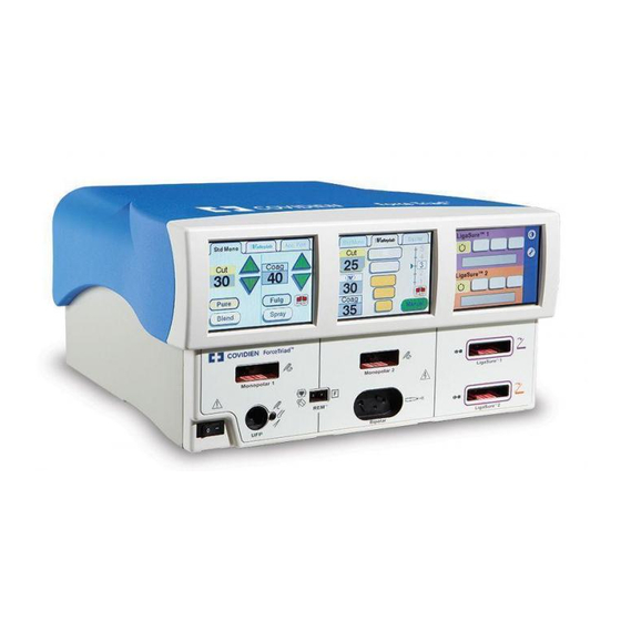
Page 19: Forcetriad Energy Platform Front Panel
ForceTriad Energy Platform Front Panel ForceTriad Energy Platform Front Panel Monopolar 1 and Accessory Touchscreen Monopolar 2 and Bipolar Touchscreen LigaSure and System Tray Touchscreen Power Switch Monopolar-Instrument Receptacle Universal-Footswitching-Accessory Receptacle REM™ Patient Return Electrode Receptacle ... -
Page 20: Forcetriad Energy Platform Back Panel
ForceTriad Energy Platform Back Panel ForceTriad Energy Platform Back Panel CAUTION LigaSure 1 Warning: Risk of Fire. Replace Fuse as Marked. 250V, F8.0A (100-240) Avertissement: Risque du feu. Remplacez les fusibles comme marqués. 250 V F8.0A (100-240) Bipolar Monopolar LigaSure 2 U.S. -
Page 21: System Conventions
System Conventions System Conventions Touchscreens The ForceTriad energy platform features a user-friendly interface with three touchscreens that allow the user to control system functions. The active touchscreen or touchscreens illuminate, and the unavailable touchscreens dim. Common Symbols Symbol Name Description... - Page 22 When maximum brightness is reached, next selection resets to the least bright setting. Wrench Selects access to the Main Menu, which provides user-selected options for language, appearance, and operation. ForceTriad Energy Platform Service Manual...
-
Page 23: Power Modes
Valleylab mode is a unique combination of hemostasis and dissection that allows the user to slow down for more hemostasis and speed up for faster dissection. Thermal spread is equal to or less than cut or blend modes. ForceTriad Energy Platform Service Manual... -
Page 24: Bipolar Modes
20 Ω and 1,000 Ω. The activation impedance safety feature does not deliver RF power to the tissue if it is not within the specified range. This is a factory-set value that cannot be reset by the user. ForceTriad Energy Platform Service Manual... -
Page 25: Ligasure Mode
Do not attempt to fuse lung tissue with LigaSure mode or instruments. LigaSure Instruments The LigaSure instruments that complete the ForceTriad tissue-fusion system include multiple reusable and single-use instruments for open and laparoscopic procedures. Each reusable instrument requires a corresponding single-use electrode. The LigaSure function is available only when using LigaSure instruments. -
Page 27: Chapter 2. Patient And Operating Room Safety
ForceTriad Energy Platform Service Manual... -
Page 28: General
If increased power settings are requested, check the patient return electrode and all instrument connections before making major power setting adjustments. Contact between the active electrode and any metal greatly increases current flow and can result in unintended surgical effect. ForceTriad Energy Platform Service Manual... - Page 29 When using a smoke evacuator in conjunction with the system, set the system volume control at a level that ensures that the activation tones can be heard. Connect only Covidien-approved footswitches. Using footswitches from other manufacturers may cause equipment malfunction.
-
Page 30: Fire/Explosion Hazard
Facial and other body hair is flammable. Water soluble surgical lubricating jelly may be used to cover hair close to the surgical site to decrease flammability. Verify that all anesthesia circuit connections are leak free before and during use of electrosurgery. ForceTriad Energy Platform Service Manual... -
Page 31: Forcetriad Energy Platform
All Covidien instruments have voltage ratings that are greater than the maximum output voltages in the system and are thus fully compatible. -
Page 32: Implanted Electronic Devices (Ieds)
ICDs, or interfere with the intended function of other IEDs. After Surgery Warning Electric Shock Hazard Always turn off and unplug the ForceTriad energy platform before cleaning. Caution Do not reprocess, reuse or resterilize instruments labeled “disposable” or “single use only.”... -
Page 33: Monopolar
Use of duty cycles greater than 25% (10 seconds active followed by 30 seconds inactive) increases the risk that heat build-up under a return electrode may be high enough to injure the patient. Do not continuously activate for longer than one minute. ForceTriad Energy Platform Service Manual... -
Page 34: Inadvertent Radio Frequency (Rf) Burns
Capacitive pads and other non-CQM patient return electrodes may not work with the system. Important A statement of compatibility from the CQM patient return electrode manufacturer should be obtained prior to the use of a non-Covidien CQM patient return electrode. Inadvertent Radio Frequency (RF) Burns Warning... -
Page 35: Laparoscopic Procedures
(Pure Cut, Blend, or Valleylab mode) to lessen the potential for the creation of capacitive currents. • Carefully insert and withdraw active electrodes from cannulas to avoid possible injury to the patient or damage to the devices. Covidien recommends against the use of laparoscopic surgery on pregnant patients. ForceTriad Energy Platform Service Manual... -
Page 36: Bipolar
LigaSure Warning LigaSure instruments are intended for use ONLY with the ForceTriad energy platform and the LigaSure vessel sealing system. Use of these instruments with other Covidien generators or with generators produced by other manufacturers may not result in electrical output for which these instruments were designed and thus may not result in the desired clinical effect. -
Page 37: Ligasure In Laparoscopic Procedures
If the instrument manufacturer recommends the use of a shunt cord (s-cord) to direct the current back to the system, you must also use a E0507-B adapter. To avoid a REM alarm, you must use a REM Polyhesive™ patient return electrode with the E0507-B adapter. ForceTriad Energy Platform Service Manual 2-11... -
Page 38: Conductive Fluid In The Surgical Site
Use of duty cycles greater than 25% (10 seconds active followed by 30 seconds inactive) increases the risk that heat build-up under a return electrode may be high enough to injure the patient. Do not continuously activate for longer than one minute. 2-12 ForceTriad Energy Platform Service Manual... -
Page 39: Chapter 3. Principles Of Operation
Chapter 3 Principles of Operation This chapter provides detailed information about how the ForceTriad energy platform functions and how the internal components interact. This chapter includes the following information: • A block diagram that illustrates how the system functions • A general description of how the system works •... -
Page 40: Block Diagram
Block Diagram Block Diagram ForceTriad Energy Platform Service Manual... - Page 41 30 CABLE LCD-INVERTER FORCETRIAD 9 CABLE LIGASURE 2 FTSW FORCETRIAD 31 CABLE LCD-INVERTER FORCETRIAD 10 CABLE REM SR-RF FORCETRIAD 32 CABLE RIBBON SCANNER FORCETRIAD (LIG 1) 11 CABLE MONO OUT FORCETRIAD 33 CABLE RIBBON SCANNER FORCETRIAD (LIG 2) 12 CABLE RF-STEERING FORCETRIAD...
-
Page 42: Functional Overview
Functional Overview Functional Overview The ForceTriad energy platform is a combination of a full-featured general-surgery electrosurgical unit and a LigaSure vessel sealing system. The monopolar and bipolar sections of the system are isolated electrosurgical outputs that provide the appropriate power for cutting, desiccating, and fulgurating tissue during monopolar and bipolar surgery. -
Page 43: High-Voltage Dc (Hvdc Pcba) Power Supply Principles
HVDC is an active discharge circuit; this circuit places a load across the output. This allows the output of the HVDC to discharge quickly no matter what the load attached to the HVDC. ForceTriad Energy Platform Service Manual... -
Page 44: Rf Pcba Principles Of Operation
RF PCBA Principles of Operation The primary purpose of the ForceTriad RF PCBA is to convert the DC voltage coming from the HVDC PCBA into a 470 kHz RF signal that is sent to the Steering Relay PCBA to be distributed to the appropriate output. -
Page 45: Sensor Circuit
In the event of a failure of the primary or backup sense circuit, dissimilar outputs are present and software detection stops delivery of RF. The user is notified with an error message displayed on the front panel of the ForceTriad energy platform. -
Page 46: Steering Relay Pcba Principles Of Operation
Steering Relay PCBA Principles of Operation To accommodate the need for high isolation between the patient and ground-referenced voltages during use, the ForceTriad Steering Relay PCBA design incorporates several different types of relays designed for very high voltage standoff. In addition, cut-outs on the PCBA increase distances at strategic locations to help reduce creepage issues. -
Page 47: Circuit Descriptions For The Forcetriad Display Pcba
Data is read out of the FIFO and presented to the displays at the pixel rate. For the ForceTriad energy platform, this yields a display refresh rate of ~46 Hz. In either case, the pixel rate must be derived from the receive clock to keep the display output in sync with the display data generation on the controller PCBA and prevent overflowing or under flowing of the pixel FIFO. -
Page 48: Barcode Driver
Footswitch data is collected and sent to the controller PCBA as well. Finally, the expansion port has an RS-232 and ECG/blanking relay interface that connects directly to the controller PCBA and DAC controlled by this FPGA. 3-10 ForceTriad Energy Platform Service Manual... -
Page 49: Power Supplies
FPGA plays that wave file twice and then stop until a new command is received. If a wave file is to be played continuously, it can be set using the duration parameter. ForceTriad Energy Platform Service Manual 3-11... -
Page 50: Footswitch Data
The controller PCBA regulates all system outputs, receives and interrupts all customer inputs, monitors the entire system for safety issues and proper functionality, and acts as the overall manager for all systems within the ForceTriad. The controller PCBA contains the host processor, Digital Signal Processors (DSP’s), Interface Control Logic PLD (ICL), data converters, and external peripherals. -
Page 51: Host Processor
DSP1 reads. Through a direct-connect serial channel (or through the ICL), the two DSPs are able to compare sensor results. DSP2 has FLASH and SDRAM memories directly connected to its address and data bus. ForceTriad Energy Platform Service Manual 3-13... -
Page 52: Interface Control Logic Pld
The DSP1 DAC also drives the voltage level of the HVPS. External Peripherals The controller PCBA has ports for talking to external peripherals through the following protocols: RS232, USB 1.1, and Ethernet. 3-14 ForceTriad Energy Platform Service Manual... -
Page 53: Chapter 4. Technical Specifications
Read all warnings, cautions, and instructions provided with this system before use. Read the instructions, warnings, and cautions provided with electrosurgical instruments before use. Specific instructions for electrosurgical instruments are not included in this manual. ForceTriad Energy Platform Service Manual... -
Page 54: Performance Characteristics
Three LCD touchscreens Connector ports LED illuminated Smart-connector readers Mounting • ForceTriad energy platform cart (FT900), Universal Mounting cart (UC8009), and/or the UC8010 Overshelf • Operating-room boom systems • Any stable, flat surface such as a table or cart top... -
Page 55: Operating Parameters
Atmospheric pressure 500 millibars to 1060 millibars Duration of storage The ForceTriad energy platform may be stored indefinitely. If the system is stored for over one year, the memory battery must be replaced, and the system must be re-calibrated in accordance with Chapter 9, Maintenance and Repair. -
Page 56: Activation Tone
High, low, high, low, high, low Seal Complete – Two 175 ms tones separated by 175 ms for each seal-complete event Error/System Alert – Three 250 ms tones separated by 250 ms for each error/system-alert event ForceTriad Energy Platform Service Manual... -
Page 57: Rem Contact Quality Monitor
Bipolar Cord E0020V, E0021S, E0022W, E360150, or E360150L. Warning Use of different Covidien cord models or cords from other manufacturers may not achieve proper electrical output for this device, thereby failing to produce the desired clinical effect. For example, Autobipolar activation/deactivation settings may not work properly using cords other than those specified by Covidien. - Page 58 < 50 W 50 W Ω – Ω Ω Ω ± 20% or ± 25 ± 20% or ± 25 (Whichever is greater) (Whichever is greater) – 501 Ω 1000 Ω ± 40% ± 20% ForceTriad Energy Platform Service Manual...
- Page 59 Reads > 2200 Reads > 2200 Ω Mode: BP Macro Load/Power All power levels 1 Ω – 2500 Ω Ω ± 20% or ± 25 (Whichever is greater) > 2500 Ω Reads > 2200 Ω ForceTriad Energy Platform Service Manual...
-
Page 60: Duty Cycle
Bipolar RF leakage < 59.2 mA RMS < 59.2 mA RMS current Monopolar RF leakage < 150 mA RMS < 100 mA RMS current LigaSure leakage < 132 mA RMS < 100 mA RMS ForceTriad Energy Platform Service Manual... -
Page 61: Input Power
Cable - H05VVF3G1.0 VDE, maximum length 15 ft. (5 m) Plug - minimum 6 A - 250 VAC Unit receptacle - IEC female, minimum 6 A - 250 VAC Important Contact your local Covidien representative for alternative internationally approved power-cord options. ForceTriad Energy Platform Service Manual... -
Page 62: Input Frequency
An ECG blanking port is provided to signal other devices that the system is active. The receptacle is a 2.5 mm mono jack. It is electrically isolated from the internal ground referenced electronics with the shell electrically connected to the chassis for ESD protection. 4-10 ForceTriad Energy Platform Service Manual... -
Page 63: Standards And Iec Classifications
Standards and IEC Classifications Standards and IEC Classifications The ForceTriad energy platform meets all pertinent clauses of the IEC 60601-1 second edition and IEC 60601-2-2 third edition. ATTENTION Consult accompanying documents. The system output is floating (isolated) with respect to ground. -
Page 64: Symbols
Bipolar instrument receptacle LigaSure related receptacle or footswitch Color-coded LigaSure footswitch symbol for matching rear panel connector to front panel receptacle REM patient return electrode receptacle Volume adjustment for activation tones Equipotential grounding point 4-12 ForceTriad Energy Platform Service Manual... -
Page 65: Class I Equipment (Iec 60601-1)
The system should not be used adjacent to or stacked with equipment other than specified in the ForceTriad Energy Platform User Guide and Service Manual. If adjacent or stacked use is necessary, the system should be observed to verify normal operation in the configuration in which it will be used. - Page 66 IEC 61000-4-11) Guidance and manufacturer's declaration - electromagnetic emissions The ForceTriad energy platform is intended for use in the electromagnetic environment specified below. The customer or the user of the system should ensure that it is used in such an environment.
- Page 67 Symbols Guidance and manufacturer's declaration - electromagnetic immunity The ForceTriad energy platform is intended for use in the electromagnetic environment specified below. The customer or the user of the system should ensure that it is used in such an environment.
- Page 68 Symbols Guidance and manufacturer's declaration - electromagnetic immunity The ForceTriad energy platform is intended for use in the electromagnetic environment specified below. The customer or the user of the system should assure that it is used in such an environment.
- Page 69 RF transmitters, an electromagnetic site survey should be considered. If the measured field strength in the location in which the ForceTriad energy platform is used exceeds the applicable RF compliance level above, the ForceTriad energy platform should be observed to verify normal operation.
- Page 70 Recommended separation distances between portable and mobile RF communication equipment and the ForceTriad energy platform The ForceTriad energy platform is intended for use in an electromagnetic environment in which radiated RF disturbances are controlled. The Customer or the user of the system can help...
-
Page 71: Output Characteristics
287.5 V 575 V 20 Ω 350 W 1.42 LigaSure Test 147.5 V 295 V 20 Ω 190 W 1.42 * An indication of a waveform’s ability to coagulate bleeders without a cutting effect. ForceTriad Energy Platform Service Manual 4-19... -
Page 72: Available Power Settings In Watts
5 W to 40 W available in 1 W increments 45 W to 95 W available in 5 W increments Bipolar (All Modes) 1 W to 40 W available in 1 W increments 45 W to 95 W available in 5 W increments 4-20 ForceTriad Energy Platform Service Manual... - Page 73 100 W to 300 W available in 10 W increments Monopolar Blend 1 W to 40 W available in 1 W increments 45 W to 95 W available in 5 W increments 100 W to 200 W available in 10 W increments ForceTriad Energy Platform Service Manual 4-21...
- Page 74 100 W to 200 W available in 10 W increments Monopolar Coag 1 W to 40 W available in 1 W increments 45 W to 90 W available in 5 W increments 100 W to 120 W available in 10 W increments 4-22 ForceTriad Energy Platform Service Manual...
-
Page 75: Output Waveforms
Monopolar Coag Fulgurate 472 kHz damped sinusoidal bursts with a repetition frequency of 30.66 kHz. 6.5% duty cycle. Spray 472 kHz damped sinusoidal bursts with a randomized repetition centered at 21.7 kHz. 4.6% duty cycle. ForceTriad Energy Platform Service Manual 4-23... -
Page 76: Output Power Vs. Resistance Graphs
Output power versus impedance for Pure cut power 100% 1500 2250 3000 3750 4500 Output power (watts) Load impedance (ohms) Output power versus power setting for Pure cut power 300 ohms Output power (watts) Power setting 4-24 ForceTriad Energy Platform Service Manual... - Page 77 Peak voltage versus power setting for Pure cut power 1200 1000 Open Circuit Peak voltage Power setting Blend Output power versus impedance for Blend power 100% 1500 2250 3000 3750 4500 Output power (watts) Load impedance (ohms) ForceTriad Energy Platform Service Manual 4-25...
- Page 78 Output power versus power setting for Blend power 300 ohms Output power (watts) Power setting Peak voltage versus power setting for Blend power 1300 Open Circuit Peak voltage Power setting 4-26 ForceTriad Energy Platform Service Manual...
- Page 79 Output power versus impedance for Fulgurate power 100% 1500 2250 3000 3750 4500 Output power (watts) Load impedance (ohms) Output power versus power setting for Fulgurate power 500 ohms Output power (watts) Power setting ForceTriad Energy Platform Service Manual 4-27...
- Page 80 2500 2000 Open Circuit 1500 1000 Peak voltage Power setting Spray Output power versus impedance for Spray power 100% 1500 2250 3000 3750 4500 Output power (watts) Load impedance (ohms) 4-28 ForceTriad Energy Platform Service Manual...
- Page 81 Output power versus power setting for Spray power 500 ohms Output power (watts) Power setting Peak voltage versus power setting for Spray power 3750 3000 2250 Open Circuit 1500 Peak voltage Power setting ForceTriad Energy Platform Service Manual 4-29...
- Page 82 Output power versus impedance for Valleylab power 100% 1500 2250 3000 3750 4500 Output power (watts) Load impedance (ohms) Output power versus power setting for Valleylab power 300 ohms Output power (watts) Power setting 4-30 ForceTriad Energy Platform Service Manual...
- Page 83 Output Power vs. Resistance Graphs Peak voltage versus power setting for Valleylab power 2500 2000 1500 Open Circuit 1000 Peak voltage Power setting ForceTriad Energy Platform Service Manual 4-31...
-
Page 84: Bipolar Graphs
Output power versus impedance for Bipolar Low power 100% 1080 1440 1800 Output power (watts) Load impedance (ohms) Output power versus power setting for Bipolar Low power 100 ohms Output power (watts) Power setting 4-32 ForceTriad Energy Platform Service Manual... -
Page 85: Bipolar Standard
Peak voltage versus power setting for Bipolar Low power Open Circuit Peak voltage Power setting Bipolar Standard Output power versus impedance for Bipolar Standard power 100% 1125 1500 1875 Output power (watts) Load impedance (ohms) ForceTriad Energy Platform Service Manual 4-33... - Page 86 Power setting Peak voltage versus power setting for Bipolar Standard power Open Circuit Peak voltage Power setting Note: Maximum peak voltage in the Bipolar Standard mode occurs at 500 not open Ω circuit. 4-34 ForceTriad Energy Platform Service Manual...
- Page 87 Output power versus impedance for Bipolar Macro power 100% 1125 1500 1875 Output power (watts) Load impedance (ohms) Output power versus power setting for Bipolar Macro power 100 ohms Output power (watts) Power setting ForceTriad Energy Platform Service Manual 4-35...
- Page 88 Output Power vs. Resistance Graphs Peak voltage versus power setting for Bipolar Macro power 500 ohms Peak voltage Power setting 4-36 ForceTriad Energy Platform Service Manual...
-
Page 89: Ligasure
Output power versus impedance for LigaSure power 3.5A 5.5A 1.0A Output power (watts) Load impedance (ohms) Peak voltage versus impedance for LigaSure power 3.5A 5.5A 1.0A Peak voltage Load impedance (ohms) ForceTriad Energy Platform Service Manual 4-37... -
Page 91: Chapter 5. System Setup
Chapter 5 System Setup This chapter describes how to set up the ForceTriad energy platform, turn it on, and configure system settings. Caution Read all warnings, cautions, and instructions provided with this system before use. Read the instructions, warnings, and cautions provided with electrosurgical instruments before use. -
Page 92: Setup
Place the system on a flat, stable surface such as a table, platform, boom system, or ForceTriad cart. Refer to the procedures for your local institution or your local codes. Plug the system power cord into the rear panel receptacle. -
Page 93: System Functions
Refer to Chapter 9, Maintenance and Repair for complete service instructions. Restore Select the Restore button on the Main menu to restore the system to the previous setup configuration. The touchscreens display the last settings entered prior to shutting down the system. ForceTriad Energy Platform Service Manual... -
Page 94: Setup
Touch the up or down arrows next to the time or date row to adjust the selected numeric field. Touch and hold the arrows to increase the number once a second. After four seconds, the numbers increase once every 100 milliseconds. ForceTriad Energy Platform Service Manual... -
Page 95: Features Menu
Touch Features in the Setup menu. Available options appear in the left touchscreen. The factory default for all features is disabled. To enable, touch AutoBipolar. A check appears in the accompanying box. To disable, touch AutoBipolar. The check is cleared from the box. ForceTriad Energy Platform Service Manual... - Page 96 Bipolar screen. The Bipolar tab changes to Auto, presenting the options and settings for autobipolar mode. For more information see the ForceTriad Energy Platform User’s Guide. To turn autobipolar mode off, touch the green Bipolar button on the Auto tab. The Auto tab changes to Bipolar.
- Page 97 Touch the green arrow buttons below the Features menu and Setup menu to return to the Main menu. When Monopolar 1 footswitching is enabled on the Features menu, the footswitching button with an X appears on the Std Mono and Valleylab tabs in the left screen. ForceTriad Energy Platform Service Manual...
- Page 98 Std Mono or Valleylab tabs on the left touchscreen. The red X appears on the button when turned off. Note: If Monopolar 1 footswitch has not been enabled, the following touchscreen appears. Enable Monopolar 1 footswitching by touching the button with the green check mark. ForceTriad Energy Platform Service Manual...
-
Page 99: Demo Mode
On the Main menu, the Demo mode button displays ‘Exit Demo’ if the system is in Demo mode. Touch the Exit Demo button on the Main menu to exit the Demo mode. The system touchscreens display the last settings entered during the Demo mode. ForceTriad Energy Platform Service Manual... -
Page 101: Chapter 6. Setup, Tests, And Adjustments
Chapter 6 Setup, Tests, and Adjustments This chapter describes how to set up, test, and calibrate the ForceTriad energy platform. After unpacking or servicing the system, set up the system, perform any required calibration, and verify correct functionality. If the system does not satisfactorily complete the self-test, re-calibrate the system, and power cycle the system. -
Page 102: Setting Up The Forcetriad Energy Platform
Verify the system is off by pressing the power switch off (O). Place the system on a stable flat surface, such as a table, platform, or Covidien cart. For details, refer to the procedures for your institution or to local codes. - Page 103 Setting Up the ForceTriad Energy Platform Turn on the system by pressing the power switch on (|). Verify the following: – All visual indicators and displays on the front panel illuminate. – Activation tones sound to verify that the speaker is working properly.
-
Page 104: Calibrating The Forcetriad Energy Platform
Calibrating the ForceTriad Energy Platform Calibrating the ForceTriad Energy Platform There are 11 calibration steps. During calibration the user verifies system-specific information, and adjusts the information if necessary. The user also adjusts the REM circuit and other values that ensure the proper operation of the system. - Page 105 Calibrating the ForceTriad Energy Platform Calibration Flow Chart Use the following flow chart to determine the order and level of calibration needed. ForceTriad Calibration Flowchart System Leakage Null Calibration LC Tuning REBOOT Calibration System Utility Calibration Set Time / Brightness...
- Page 106 Calibrating the ForceTriad Energy Platform Calibration Levels Chapter 8, Replacement Procedures references the calibration levels required after a component replacement. The following table defines calibration level. Level 0 Periodic safety check Level 1 Scanner calibration Level 2 System leakage null calibration...
- Page 107 Calibrating the ForceTriad Energy Platform Select the Stop RF button when the optimal current value has been reached. Turn the system off. ® Apply Loctite , or equivalent, to the inductor potentiometer. Reinstall the cover on the system. Position the cover above the chassis and slide it down.
- Page 108 Calibrating the ForceTriad Energy Platform Using a stylus (or equivalent) gently touch the center of the cross-hair targets. Complete all targets from left screen to right screen. When the on-screen calibration instructions have been completed and saved, select the red X button to exit to the next calibration step.
-
Page 109: Periodic Safety Check (Routine Maintenance)
“one hand rule”, etc. Electric Shock Hazard Do not touch any exposed wiring or conductive surfaces while the system is disassembled and energized. Never wear a grounding strap when working on an energized system. ForceTriad Energy Platform Service Manual... - Page 110 A summary of the periodic safety checks is: • Inspect the system and accessories • Inspect the internal components • Test the system • Verify REM function • Verify cross coupling • Confirm outputs • Check leakage current and ground resistance 6-10 ForceTriad Energy Platform Service Manual...
-
Page 111: Recommended Test Equipment
• REM plug • Digital voltmeter (3.5 digit minimum) • Handswitching electrosurgical pencils • Force TriVerse electrosurgical device (barcode) • Covidien footswitch pedals (bipolar, monopolar, LigaSure) • Potentiometer adjustment tool • Low-frequency test circuit • Test-cable set • Autobipolar load box •... -
Page 112: Inspecting The System And Accessories
– Verify the accessory port tab (Acc. Port) on the Monopolar 1 screen becomes active, indicating the adapter has been detected. If the UFP port is damaged or unusable, return the system to Covidien Technical Service. For more information, see Covidien Technical Service on page 9-4. -
Page 113: Inspecting The Internal Components
(Std Mono) becomes active. For the Force Triverse electrosurgical pencil, the Valleylab tab becomes active. If either of the monopolar receptacles is damaged, contact Covidien Technical Service. (see page 9-4). Check the Patient Return Electrode (REM) receptacle for a broken pin or an obstruction. - Page 114 Inspect each PCBA for damaged components, wires, cracks, and corrosion: If there is evidence of damage on the Controller PCBA, Steering Relay PCBA, Display PCBA, Footswitch/Audio PCBA, HVDC Power Supply PCBA, or the RF PCBA, contact Covidien Technical Service (see page 9-4). 6-14 ForceTriad Energy Platform Service Manual...
-
Page 115: Testing The System
To exit Demo mode, either turn the system off and restart it, or follow the steps in the Exit Demo Mode section that follows. ForceTriad Energy Platform Service Manual 6-15... -
Page 116: Entering Debug Mode
While in Debug Mode, the Open Or Close Loop selection in the lower-left of the screen should always remain in Closed Loop. Open Loop should never be used during preventive maintenance of the ForceTriad system. Irreversible damage may occur to the unit if Open Loop control is used improperly. -
Page 117: Testing The Low-Voltage Power Supply
Activate the Mono 1 cut from the hand switch. Verify that the audio is active and distortion free. Rotate the audio knob on the rear of the system from high- to low-volume ranges. Verify that the audio is active and distortion free. ForceTriad Energy Platform Service Manual 6-17... -
Page 118: Verifying Rem Function
The system is in autobipolar mode when an A button appears in the middle window. Set the bipolar power to 20 W. Verify that the bipolar power setting does not change when the Auto button is active or inactive. 6-18 ForceTriad Energy Platform Service Manual... -
Page 119: Verifying Cross Coupling
Connect a 1070 Ω load to the bipolar output. Verify that no RF generation occurs. Disable the Autobipolar function before continuing to the next section. Verifying Cross Coupling Equipment required: • 2-button hand switch • bipolar foot switch • bipolar cable • UFP adapter ForceTriad Energy Platform Service Manual 6-19... - Page 120 LigaSure 2 current. Connect a 200 Ω load from the left LigaSure 2 output through the current transformer to the right LigaSure 2 output. Activate the following modes one at a time. – Mono 1 Cut Pure – Mono 1 Coag Spray 6-20 ForceTriad Energy Platform Service Manual...
-
Page 121: Confirming Power Delivery At Receptacle
The system must be in the Demo mode to confirm outputs. The ForceTriad is designed to function only as a Return Electrode Contact Quality Monitor (RECQM) equipped unit. For instructions to disable the RECQM circuit, see Enable Demo Mode on page 6-15. - Page 122 7 and 8 on page 6-8 then repeat this procedure. If the output for one or more cut modes remains outside the specified range, contact Covidien Technical Service (see page 9-4). Repeat steps 2 through 5 for Monopolar 2 output.
- Page 123 7 and 8 on page 6-8, then repeat this procedure. If the output for one or more coag modes remains outside the specified range, contact Covidien Technical Service (see page 9-4). Repeat steps 2 through 5 for Monopolar 2 output.
- Page 124 If the output is outside the specified range, calibrate the voltage and current as described in calibration steps 7 and 8 on page 6-8, then repeat this procedure. If the output for one or more modes remains outside the specified range, contact Covidien Technical Service (see page 9-4).
-
Page 125: Verifying Power Output
If the output is outside the specified range, calibrate the voltage and current as described in calibration steps 7 and 8 on page 6-8, then repeat this procedure. If the output for one or more modes remains outside the specified range, contact Covidien Technical Service (see page 9-4). - Page 126 Activate the 3-button pencil in Monopolar 1 and measure between the 3-button pencil and the REM jack using a 300 Ω load. Verify that the power outputs are within the specified range for each output mode. 6-26 ForceTriad Energy Platform Service Manual...
- Page 127 Press RF OFF button to stop the flow of RF to the port. Verify that the power outputs are within the specified range for each output mode. Repeat steps 1 through 4 using LigaSure 2 Port as the input for Port Selection in the Debug screen. ForceTriad Energy Platform Service Manual 6-27...
-
Page 128: Checking High-Frequency Leakage Current
100 mA for any mode. If the high-frequency leakage exceeds 100 mA, perform a power calibration. If the measurements still exceed 100 mA, contact Covidien Technical Service (see page 9-4) for further instructions. Repeat steps 1 through 3 for monopolar 1 and monopolar 2 using the left tine for each receptacle. -
Page 129: Safety Testing In Accordance With Iec601
Safety Testing in Accordance with IEC601 If the high-frequency leakage exceeds 69 mA, perform a power calibration. If the measurements still exceed 69 mA, contact Covidien Technical Service (see page 9-4) for further instructions. Checking LigaSure High-Frequency Leakage Current Notice The system must be in Debug mode with Mode Selection set to LigaSure Test, and the port set to LigaSure 1 Port. -
Page 130: Checking Low-Frequency Leakage Current
Determine the leakage current using the conventional 1 mA for each 1 mV. Verify under normal conditions (ground closed, normal polarity) the leakage current is less than 300 mA. If the leakage current is greater than 300 mA, contact Covidien Technical Service (see page 9-4). -
Page 131: Ground Bond Testing
Safety Testing in Accordance with IEC601 Verify under normal conditions (ground closed, normal polarity) the leakage current is less than 10 mA. If the leakage current is greater than 10 mA, contact Covidien Technical Service (see page 9-4). Verify single fault conditions (ground open) the leakage current is less than or equal to 50 mA. -
Page 132: Preventive Maintenance Check Sheet
+ 5 VDC 5.00 V to 5.20 V +12 VDC 11.4 V to 13.2 V -12 VDC -12.36 V to -11.64 V Audio Tone audible at high and low ranges Accept Y or N 6-32 ForceTriad Energy Platform Service Manual... - Page 133 RF generation stops when disconnected Accept Y or N Ω RF generation at 20 W when 1070 is connected Accept Y or N RF generation does not occur when input is shorted Accept Y or N together ForceTriad Energy Platform Service Manual 6-33...
- Page 134 Mono 1 Cut 0 mA - 140 mA LigaSure 1 Mono 1 Spray 0 mA - 140 mA Mono 1 Cut 0 mA - 140 mA LigaSure 2 Mono 1 Spray 0 mA - 140 mA 6-34 ForceTriad Energy Platform Service Manual...
- Page 135 452 mA - 525 mA 300 Ω Cut 922 mA - 1072 mA Monopolar 2 (Force TriVerse) 300 Ω VL Mode 753 mA - 876 mA 500 Ω Coag 452 mA - 525 mA ForceTriad Energy Platform Service Manual 6-35...
- Page 136 Testing Valleylab Mode Output - 300 Ω 10 W VL Mode 146 mA - 218 mA 75 W VL Mode 461 mA - 536 mA 200 W VL Mode 753 mA - 876 mA 6-36 ForceTriad Energy Platform Service Manual...
- Page 137 452 mA - 525 mA Testing LigaSure Output - 50 Ω LigaSure 1 LigaSure 2 288 mA - 355 mA 2.7 A 761 mA - 885 mA LigaSure 5.5 A 1540 mA - 1790 mA ForceTriad Energy Platform Service Manual 6-37...
- Page 138 Bipolar Low (Left Tine) 0 mA - 69 mA Bipolar Standard (Right Tine) 0 mA - 69 mA Bipolar Macro (Right Tine) 0 mA - 69 mA Bipolar Low (Right Tine) 0 mA - 69 mA Continued 6-38 ForceTriad Energy Platform Service Manual...
- Page 139 0 mA - 10 mA (Mains to Applied Parts) Open Ground 0 mA - 50 mA Ground Bond Test Accept Y, N, or N/A Valleylab Exchange Unit Docked to Valleylab Exchange Accept Y, N, or N/A ForceTriad Energy Platform Service Manual 6-39...
-
Page 141: Chapter 7. Troubleshooting
• Identify and correct the malfunction • If a system error was displayed, take the appropriate action to correct the condition. Additional technical information may be available through Covidien Technical Service (see page 9-4). ForceTriad Energy Platform Service Manual... -
Page 142: Inspecting The Forcetriad Energy Platform
(H = Host, 1 = Main Digital Signal Processor, 2 = Backup Digital Signal Processor) • 0.0014 identifies the version of code. • L1603 identifies the line of code at which the error occurred. Important When contacting Covidien Service, include all screen information. ForceTriad Energy Platform Service Manual... -
Page 143: System-Error Descriptions
Should you be unable to correct the issue after using the troubleshooting guide, contact Covidien Technical Service (see page 9-4). E2 ERR_SE_ICL_ERROR Unable to communicate to hardware using the Host ICL registers. - Page 144 Responding to System Errors If the new board does not correct the issue, contact your local Covidien Technical Service for further instructions (see page 9-4). E6 ERR_SE_RTOS_FAIL Software error - A real time operations system failure. Open the cover to the unit and inspect the controller board. Verify that the board is securely seated and fastened as expected.
- Page 145 If the unit still displays the error and/or the recalibration does not correct the issue, replace the controller board and perform a level-6 calibration. If the new board does not correct the issue, contact your local Covidien Technical Service for further instructions (see page 9-4).
- Page 146 If the unit still displays the error, replace the controller board and perform a level-6 calibration of the system as described in Calibration Levels on page 6-6. If the new board does not correct the issue, contact your local Covidien Technical Service for further instructions (see page 9-4).
- Page 147 If the controller board replacement does not correct the error, replace the RF board and perform a level-5 calibration. If the new boards do not correct the issue, contact your local Covidien Technical Service for further instructions (see page 9-4).
- Page 148 If replacing the HVDC board does not correct the error, replace the LVPS and perform a level 0 calibration. If the new board does not correct the issue, contact your local Covidien Technical Service for further instructions (see page 9-4).
- Page 149 If the unit still displays the error and/or the recalibration does not correct the issue, replace the controller board and perform a level-6 calibration. If the new board does not correct the issue, contact your local Covidien Technical Service for further instructions (see page 9-4).
- Page 150 If the unit still displays the error and/or the recalibration does not correct the issue, replace the controller board and perform a level-6 calibration. If the new board does not correct the issue, contact your local Covidien Technical Service for further instructions (see page 9-4).
- Page 151 If replacing the display does not correct the error, replace the controller board and perform a level-6 calibration. If the new board does not correct the issue, contact your local Covidien Technical Service for further instructions (see page 9-4). E270 ERR_NR_AUDIBLE_ERROR Audio self-test error.
- Page 152 If the unit still displays the error and/or the recalibration does not correct the issue, replace the FTSW board and perform a level-2 calibration. If the new board does not correct the issue, contact your local Covidien Technical Service for further instructions (see page 9-4).
- Page 153 If replacing the system scanners does not correct the issue, replace the controller board and perform a level-6 calibration. If the new board does not correct the issue, contact your local Covidien Technical Service for further instructions (see page 9-4).
- Page 154 If the unit still displays the error and/or the recalibration does not correct the issue, replace the RF board and perform a level-5 calibration. If the new board does not correct the issue, contact your local Covidien Technical Service for further instructions (see page 9-4).
- Page 155 If the unit still displays the error, replace the RF board and perform a level-5 calibration of the system as described in Calibration Levels on page 6-6. If the new board does not correct the issue, contact your local Covidien Technical Service for further instructions (see page 9-4).
- Page 156 If the unit still displays the error, replace the controller board and perform a level-6 calibration of the system as described in Calibration Levels on page 6-6. If the new board does not correct the issue, contact your local Covidien Technical Service for further instructions (see page 9-4).
- Page 157 If the unit still displays the error, replace the controller board and perform a level-6 calibration of the system as described in Calibration Levels on page 6-6. If the new board does not correct the issue, contact your local Covidien Technical Service for further instructions (see page 9-4).
- Page 158 If the unit still displays the error and/or the recalibration does not correct the issue, replace the controller board and perform a level-6 calibration. If the new board does not correct the issue, contact your local Covidien Technical Service for further instructions (see page 9-4).
- Page 159 If replacing the HVDC board does not correct the error, replace the controller board and perform a level-6 calibration. If the new components do not correct the issue, contact your local Covidien Technical Service for further instructions (see page 9-4).
- Page 160 If replacing the RF board does not correct the error, replace the HVDC board and perform a level-4 calibration. If the new components do not correct the issue, contact your local Covidien Technical Service for further instructions (see page 9-4).
- Page 161 If replacing the controller board does not correct the error, replace the HVDC board and perform a level-4 calibration. If the new boards do not correct the issue, contact your local Covidien Technical Service for further instructions (see page 9-4).
- Page 162 If the unit still displays the error, replace the controller board and perform a level-6 calibration of the system as described in Calibration Levels on page 6-6. If the new board does not correct the issue, contact your local Covidien Technical Service for further instructions (see page 9-4).
- Page 163 If replacing the scanner does not correct the error, replace the scanner cables and perform a level-1 calibration. If the new components do not correct the issue, contact your local Covidien Technical Service for further instructions (see page 9-4). E301 ERR_NR_LOW_BATTERY Battery self-test failure.
- Page 164 If replacing the controller board does not correct the error, replace the LVPS and perform a level 0 calibration. If the new boards do not correct the issue, contact your local Covidien Technical Service for further instructions (see page 9-4).
- Page 165 If the unit still displays the error, replace the controller board and perform a level-6 calibration of the system as described in Calibration Levels on page 6-6. If the new board does not correct the issue, contact your local Covidien Technical Service for further instructions (see page 9-4).
- Page 166 If replacing the controller board does not correct the error, replace the HVDC board and perform a level-4 calibration. If the new boards do not correct the issue, contact your local Covidien Technical Service for further instructions (see page 9-4).
- Page 167 If replacing the scanner and cables does not correct the error, replace the controller board and perform a level-6 calibration. If the new boards do not correct the issue, contact your local Covidien Technical Service for further instructions (see page 9-4).
- Page 168 If replacing the displays do not correct the error, replace the controller board and perform a level-6 calibration. If the new boards do not correct the issue, contact your local Covidien Technical Service for further instructions (see page 9-4). E311 ERR_NR_INVALID_RF_HDW_CONFIG The host has an invalid combination of hardware versions.
-
Page 169: Chapter 8. Replacement Procedures
• Display PCBA • Barcode Scanner • Output Receptacles • Barcode-Scanner Cables • System Displays • System-Display Cables • System Fans • Scan-Stand Label The parts used in these procedures are listed in Chapter 10, Service Parts. ForceTriad Energy Platform Service Manual... -
Page 170: Removing And Reinstalling The Front Panel
Steering-Relay PCBA to HVDC PCBA Rotate the top of the front-panel assembly downwards until the Steering-Relay PCBA clears the chassis top rail. Lift the front-panel assembly away from the chassis. Complete the steps for replacing an internal component. ForceTriad Energy Platform Service Manual... - Page 171 Position the cover above the chassis and slide it down. Install the four screws that secure the cover to the chassis. Recalibrate the system as described in Calibration Levels on page 6-6. Front Panel. ForceTriad Energy Platform Service Manual...
-
Page 172: Fuse Replacement
Replace each fuse with one of the same type and rating. Slide the fuse drawer into its slot until it snaps into place. Connect the power cord to the rear panel. Fuse Drawer ForceTriad Energy Platform Service Manual... -
Page 173: Battery Replacement
Calibrate the system after every battery replacement. Calibration values are lost when the battery is replaced. Refer to Calibrating the ForceTriad Energy Platform on page 6-4 for instructions. Turn off the system. Disconnect the power cord from the wall receptacle. -
Page 174: Low-Voltage Power Supply (Lvps) Replacement
Reconnect the cable assemblies. Position the cover above the chassis and slide it down. Install the four screw that secure the cover to the chassis. ForceTriad Energy Platform Service Manual... - Page 175 Low-Voltage Power Supply (LVPS) Replacement Perform a level-0 calibration of the system as described in Calibration Levels on page 6-6. Low-Voltage Power Supply ForceTriad Energy Platform Service Manual...
-
Page 176: Footswitch/Audio Pcba Replacement
Position the cover above the chassis and slide it down. Install the four screws that secure the cover to the chassis. Perform a level-2 calibration of the system as described in Calibration Levels on page 6-6. ForceTriad Energy Platform Service Manual... - Page 177 Footswitch/Audio PCBA Replacement Footswitch/Audio PCBA ForceTriad Energy Platform Service Manual...
-
Page 178: Controller Pcba Replacement
Perform a level-6 calibration of the system as described in Calibration Levels on page 6-6. Retrieve the system serial number from the rear of the system. This number is required when contacting customer service. 8-10 ForceTriad Energy Platform Service Manual... - Page 179 Obtain a serial number packet to update the newly replaced board to match the system serial number, contact customer service at: valleylab.technicalservice@covidien.com. After receiving the serial number packet, connect the system to Valleylab Exchange to ensure the latest software version is installed. Controller PCBA ForceTriad Energy Platform Service Manual 8-11...
-
Page 180: High-Voltage Dc (Hvdc) Pcba Replacement
Position the cover above the chassis and slide it down. Install the four screws that secure the cover to the chassis. Perform a level-4 calibration of the system as described in Calibration Levels on page 6-6. 8-12 ForceTriad Energy Platform Service Manual... - Page 181 High-Voltage DC (HVDC) PCBA Replacement High-Voltage DC (HVDC) PCBA ForceTriad Energy Platform Service Manual 8-13...
-
Page 182: Rf Pcba Replacement
Install the new RF PCBA by lowering and sliding backwards. Reinstall the nine screws securing the RF PCBA to the chassis. Reconnect cable assemblies: Footswitch/audio PCBA to RF PCBA LVPS PCBA to RF PCBA 8-14 ForceTriad Energy Platform Service Manual... - Page 183 Position the cover above the chassis and slide it down. Install the four screws that secure the cover to the chassis. Perform a level-5 calibration of the system as described in Calibration Levels on page 6-6. RF PCBA ForceTriad Energy Platform Service Manual 8-15...
-
Page 184: Steering-Relay Pcba Replacement
PCBAs. Notice Calibrate the system after you install a new Steering/Relay PCBA. Refer to Calibrating the ForceTriad Energy Platform on page 6-4 for instructions. Notice Perform all the steps including the recalibration listed below. Failure to recalibrate the system after replacing components may result in the system becoming inoperable. - Page 185 Reinstall the front-panel assembly; see Reinstalling the Front Panel on page 8-3. Perform a level-5 calibration of the system as described in Calibration Levels on page 6-6. Steering-Relay PCBA ForceTriad Energy Platform Service Manual 8-17...
-
Page 186: Display Pcba Replacement
Reinstall the Steering-Relay PCBA; see Steering-Relay PCBA Replacement on page 8- Reinstall the front-panel assembly; see Reinstalling the Front Panel on page 8-3. Perform a level-3 calibration of the system as described in Calibration Levels on page 6-6. 8-18 ForceTriad Energy Platform Service Manual... - Page 187 Display PCBA Replacement Display PCBA ForceTriad Energy Platform Service Manual 8-19...
-
Page 188: Barcode Scanner Replacement
Use an antistatic container for transport of electrostatic-sensitive components and PCBAs. Notice Calibrate the system after you install a new Barcode Scanner. Refer to Calibrating the ForceTriad Energy Platform on page 6-4 for instructions. Notice Perform all the steps including the recalibration listed below. Failure to recalibrate the system after replacing components may result in the system becoming inoperable. - Page 189 Barcode Scanner Replacement Barcode Scanner ForceTriad Energy Platform Service Manual 8-21...
-
Page 190: Output Receptacle Replacement
Remove the three screws securing the Monopolar 2 receptacle to the front panel. Remove the scanner shroud. Install the new Monopolar 2 receptacle and scanner shrouds in the front panel using the three screws. 8-22 ForceTriad Energy Platform Service Manual... - Page 191 Remove the two screws securing the REM receptacle to the front panel. Note the length of each screw. Remove the REM retaining bracket. Install the new REM receptacle in the front panel. Replace the REM retaining bracket. Secure the REM receptacle and bracket using the two screws. ForceTriad Energy Platform Service Manual 8-23...
- Page 192 Reinstall the Steering-Relay PCBA; see Steering-Relay PCBA Replacement on page 8- Reinstall the front-panel assembly; see Reinstalling the Front Panel on page 8-3. Perform a level-5 calibration of the system as described in Calibration Levels on page 6-6. Output Receptacles 8-24 ForceTriad Energy Platform Service Manual...
-
Page 193: Barcode-Scanner Cables
Position the cover above the chassis and slide it down. Install the four screws that secure the cover to the chassis. Perform a level-1 calibration of the system as described in Calibration Levels on page 6-6. Barcode-Scanner Cables ForceTriad Energy Platform Service Manual 8-25... -
Page 194: System Displays
LCD/ touch screen. Repeat the process as needed for the remaining two screens. Properly discard the damaged LCD/touch screens and locate the replacement components. 8-26 ForceTriad Energy Platform Service Manual... - Page 195 Position the cover above the chassis and slide it down. Install the four screws that secure the cover to the chassis. Perform a level-3 calibration of the system as described in Calibration Levels on page 6-6. System Display ForceTriad Energy Platform Service Manual 8-27...
-
Page 196: System Display Cables
Replace the cables and reconnect them to the LCD/touch screen. Reinstall the steering relay and front-panel assembly. Position the cover above the chassis and slide it down. Install the four screws that secure the cover to the chassis. 8-28 ForceTriad Energy Platform Service Manual... - Page 197 System Display Cables Perform a level-3 calibration of the system as described in Calibration Levels on page 6-6. System Display Cables ForceTriad Energy Platform Service Manual 8-29...
-
Page 198: System Fans
Position the cover above the chassis and slide it down. Install the four screws that secure the cover to the chassis. Perform a level 0 calibration of the system as described in Calibration Levels on page 6-6. 8-30 ForceTriad Energy Platform Service Manual... - Page 199 System Fans System Fans ForceTriad Energy Platform Service Manual 8-31...
-
Page 200: Scan Stand Label
Install the new scan stand label into the receptacle ensuring that it is centered within the indentations on the scan stand. Indentations vary between revision levels of the system. Perform a level-1 calibration of the system as described in Calibration Levels on page 6-6. 8-32 ForceTriad Energy Platform Service Manual... - Page 201 Scan Stand Label Scan Stand Label ForceTriad Energy Platform Service Manual 8-33...
-
Page 203: Chapter 9. Maintenance And Repair
Read all warnings, cautions, and instructions provided with this system before use. Read the instructions, warnings, and cautions provided with electrosurgical instruments before use. Specific instructions for electrosurgical instruments are not included in this manual. ForceTriad Energy Platform Service Manual... -
Page 204: Responsibility Of The Manufacturer
Responsibility of the Manufacturer Responsibility of the Manufacturer Covidien is responsible for the safety, reliability, and performance of the system only if all of the following conditions have been met: • Installation and set-up procedures in this manual are followed. -
Page 205: Cleaning
Product Service Covidien recommends that all ForceTriad systems be returned to the manufacturer for all service requirements. If any service is required without returning the system to the manufacturer, Covidien recommends that only qualified personnel service the ForceTriad system. -
Page 206: Adjustment To Factory Specification (Calibration)
Contact a Covidien technical service representative by telephone, email, or through the Internet: • USA and Canada: 1-800-255-8522 Option 2 • International: 1-303-476-7996 • Email: valleylab.technicalservice@covidien.com • Internet: www.forcetriad.com For a complete list of service centers worldwide, please refer to the Covidien web site: http://www.valleylab.com ForceTriad Energy Platform Service Manual... -
Page 207: Chapter 10. Service Parts
Chapter 1 0 Service Parts Replacement parts for the ForceTriad energy platform are listed in this chapter. All components must be replaced with parts of identical construction and value acquired from Covidien Customer Service Centers. Covidien does not recommend nor supply components for field replacement of surface-mount components. -
Page 208: Ordering Replacement Parts
– RF PCBA – Steering Relay PCBA – HVDC PCBA – Display PCBA – Footswitch PCBA – Controller PCBA – Software build version If the information cannot be obtained, contact Covidien Technical Service (see page 9-4). 10-2 ForceTriad Energy Platform Service Manual... -
Page 209: Replacement Components
• Steering Relay PCBA • FTSW PCBA • Display PCBA The following system components can be replaced: • Barcode scanner • System display • LVPS • System fans • Scan stand label • Front panel assembly ForceTriad Energy Platform Service Manual 10-3... -
Page 210: Replacing Cable Assemblies
30 CABLE LCD-INVERTER FORCETRIAD 9 CABLE LIGASURE 2 FTSW FORCETRIAD 31 CABLE LCD-INVERTER FORCETRIAD 10 CABLE REM SR-RF FORCETRIAD 32 CABLE RIBBON SCANNER FORCETRIAD (LIG 1) 11 CABLE MONO OUT FORCETRIAD 33 CABLE RIBBON SCANNER FORCETRIAD (LIG 2) 12 CABLE RF-STEERING FORCETRIAD... - Page 212 Part No. 1040472 COVIDIEN, COVIDIEN with logo and Covidien logo are U.S. and internationally registered trademarks of Covidien AG. Loctite is a registered trademark of Henkel Co. Other brands are trademarks of a Covidien company. U.S. Patents 5,370,645; 5,372,596; 5,772,659; 6,068,627; 6,203,541;...
Need help?
Do you have a question about the ForceTriad and is the answer not in the manual?
Questions and answers