Table of Contents
Advertisement
Advertisement
Table of Contents

Related Manuals for Covidien Nellcor PM10N


Summary of Contents for Covidien Nellcor PM10N
- Page 1 Service Manual Nellcor Portable SpO Patient Monitoring System...
- Page 2 COVIDIEN, COVIDIEN with logo, and Covidien logo and Positive Results for Life are U.S. and internationally registered trademarks of Covidien AG. ™* brands are trademarks of their respective owner. Other brands are trademarks of a Covidien company.
-
Page 3: Table Of Contents
Covidien Service ........ - Page 4 Firmware Upgrade ............3-11 Modification and Testing Overview .
- Page 5 List of Tables Table 1-1. Safety Symbol Definitions................1-2 Table 2-1. Service Menu Settings..................2-2 Table 3-1. Monitoring Status Codes.................3-6 Table 4-1. Required Test Equipment ................4-2 Table 4-2. Patient Modes .....................4-5 Table 4-3. Functional Tests with SRC-MAX..............4-27 Table 5-1. Error Conditions and Resolutions ..............5-2 Table 5-2. System Error Codes ...................5-6 Table 6-1. Spare Parts List by Callout Number.............6-2 Table 6-2. Monitoring System Accessories..............6-4 Service Manual...
- Page 6 Page Left Intentionally Blank Service Manual...
- Page 7 List of Figures Figure 2-1. Service Menu ......................... 2-3 Figure 3-1. Mini-USB Port ........................ 3-3 Figure 3-2. Transfer Data Type ...................... 3-4 Figure 3-3. Transfer Data by USB ....................3-4 Figure 3-4. Sample Monitoring History Printout ..............3-5 Figure 3-5. Sample Bridge Driver Installer Window .............. 3-7 Figure 3-6. ...
- Page 8 Figure 4-29. SRC-MAX Increase to 200 BPM ................4-30 Figure 4-30. SRC-MAX Decrease to 60 BPM ................4-30 Figure 4-31. SRC-MAX %SpO2 Increase to 90 ............... 4-31 Figure 4-32. SRC-MAX %SpO2 Decrease to 75 ..............4-32 Figure 4-33. SRC-MAX High Modulation ................. 4-33 Figure 4-34. BPM of 200 with High Modulation ..............4-34 Figure 4-35. ...
-
Page 9: Overview
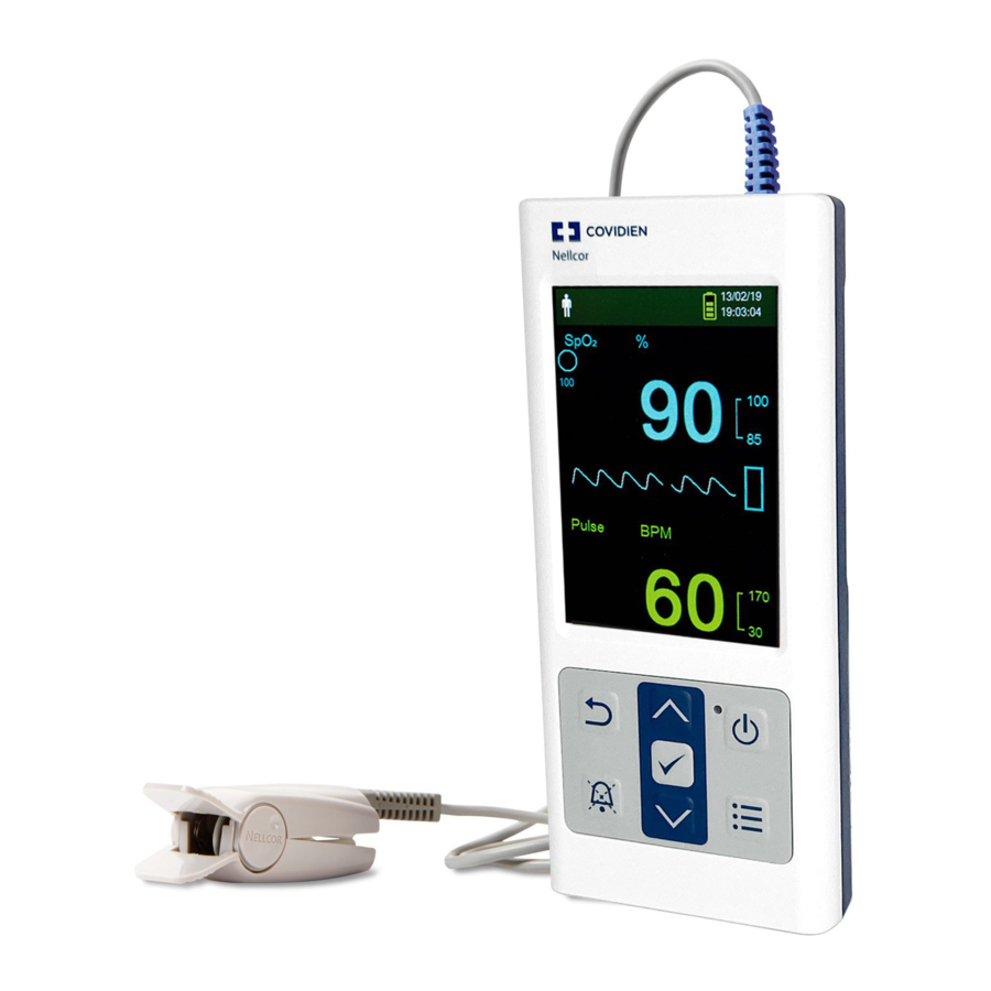
1 Introduction Overview This manual contains information for servicing the Nellcor™ portable SpO patient monitoring system. This manual applies to the following product: PM10N Note: Before use, carefully read this manual, the Operator’s Manual, accessory Instructions for Use, and all precautionary information and specifications. -
Page 10: Safety Information
Introduction Safety Information This section contains important safety information related to general use of the Nellcor™ portable patient monitoring system. Other important safety information appears throughout the manual. The Nellcor™ portable SpO patient monitoring system is referred to as the “monitoring system”... -
Page 11: Service Procedures
Safety Information Service Procedures 1.2.3 WARNING: To avoid possible injury, do not attempt to service the monitoring system if there are any signs of burning or smoking coming from the monitoring system. WARNING: Before attempting to service the monitoring system, disconnect it from the patient to avoid possible injury to the patient. -
Page 12: Monitoring System Operation And Service
Introduction Monitoring System Operation and Service 1.2.4 WARNING: Inspect the monitoring system and all accessories before use to ensure there are no signs of physical damage or improper function. Do not use if damaged. WARNING: To ensure accurate performance and prevent device failure, do not expose the monitoring system to extreme moisture, such as direct exposure to rain. -
Page 13: Patient Monitoring And Safety
Request a qualified service technician confirm the monitoring system is functioning correctly. WARNING: For best product performance and measurement accuracy, use only accessories supplied or recommended by Covidien. Use accessories according to their respective Instructions for Use. Service Manual... -
Page 14: Sensors, Cables, And Other Accessories
WARNING: Do not use any other cables to extend the length of the Covidien-approved interface cable. Increasing the length will degrade signal quality and may lead to inaccurate measurements. WARNING: To prevent damage, avoid undue bending of the sensor cable. -
Page 15: Connections With Other Equipment
Safety Information Caution: This device has been tested and found to comply with the limits for medical devices related to IEC 60601-1-2: 2007 and IEC 60601-1-2:2014. These limits are designed to provide reasonable protection against harmful interference in a typical medical installation. ... -
Page 16: Obtaining Technical Assistance
Covidien representative www.covidien.com When calling Covidien or a local Covidien representative, have the monitoring system serial number available. The serial number label is located on the bottom of the monitoring system. Provide the firmware version number displayed during the power-on self-test (POST). -
Page 17: Warranty Information
Covidien shall not be liable for errors contained herein or for incidental or consequential damages in connection with the furnishing, performance, or use of this material. - Page 18 Introduction Page Left Intentionally Blank 1-10 Service Manual...
-
Page 19: Service Menu Options
WARNING: For best product performance and measurement accuracy, use only accessories supplied or recommended by Covidien. Use accessories according to their respective Instructions for Use. WARNING: The sensor disconnect error message and associated alarm indicate the pulse oximetry sensor is either disconnected or has faulty wiring. -
Page 20: Table 2-1. Service Menu Settings
Service Menu Options The monitoring system contains a Service Menu that is accessible only by password. Contact Technical Services (reference Technical Services, page 1-8) for the default passwords for all restricted menus and functions. The monitoring system ships with the Service Menu factory default settings listed in Table 2-1. -
Page 21: Power On Settings
Service Menu Overview Figure 2-1. Service Menu Power On Settings 2.3.1 Caution: Last Settings should only be used in a service situation, not during normal operation. Note: Once changes are made to any settings, you must choose Last Settings or Institutional Defaults to have those settings saved when the monitoring system is powered off. -
Page 22: Alarm Silence Duration
Service Menu Options Note: The visual alarm (the yellow background behind the SpO or pulse rate reading) is always enabled, even when the audible alarm is disabled. Alarm Silence Duration 2.3.3 The amount of time the audible alarm remains silent after the Silence Alarm button is pressed. Options include 30, 60, 90, and 120 seconds (default). -
Page 23: Alarm Priority Settings
Service Menu Overview SPDout, 19200 baud • SPDout, 115200 baud • Alarm Priority Settings 2.3.8 Allows the setting of alarm priorities for Sensor Disconnect, Sensor Off, Sensor Failure, SpO , and Pulse Rate alarms. Reference Table 2-1 on page 2-2. Languages 2.3.9 Displays most menu items in the chosen language (reference... -
Page 24: Covidien Service
Service Menu Options Covidien Service 2.3.13 For Covidien personnel only. Service Manual... -
Page 25: Data Management
Download stored monitoring history — Monitoring history can be downloaded to a PC • using the HyperTerminal™* program or other data transmission and analysis tools. Upgrade the monitoring system’s firmware — Occasionally, Covidien will provide • upgrades to the firmware for the monitoring system, which must be loaded via the mini-USB port. -
Page 26: Monitoring History Download
Data Management Monitoring History Download 3.2.1 WARNING: Replacing the coin cell battery for the main board resets the monitoring system’s date and time settings. Integrity of existing patient data will be questionable. Reset the date and time after replacing this battery with a known good battery. ... -
Page 27: Figure 3-1. Mini-Usb Port
External Data Communication Data transfer by USB port relies on existing communication software drivers for USB-based devices already on the computer, so should not require any modification of the drivers used by the USB interface. If, for some reason, the computer does not have the correct USB driver, use the device driver provided on the product CD or from Technical Services. -
Page 28: Figure 3-2. Transfer Data Type
Data Management Figure 3-2. Transfer Data Type Select By USB. Figure 3-3. Transfer Data by USB The data is transferred, and a progress bar is displayed. If desired, select Cancel to abort the transmission. The Output Complete message is displayed when the transmission is complete. Service Manual... -
Page 29: Figure 3-4. Sample Monitoring History Printout
External Data Communication To interpret downloaded monitoring history Examine monitoring history on the HyperTerminal™* program screen, in a spreadsheet, or on a printout from the personal computer. Figure 3-4. Sample Monitoring History Printout Product column headings Data source, firmware version, and system settings Patient data column headings Lists appropriate time and data headings Time column... -
Page 30: Table 3-1. Monitoring Status Codes
Insert the Nellcor™ portable SpO patient monitoring system compact disc (CD) into the designated personal computer (PC). Copy the COVIDIEN USB to UART Bridge Driver zip file to the PC, installing it in the desired program folder. Right-click on the zipped folder. -
Page 31: Figure 3-5. Sample Bridge Driver Installer Window
External Data Communication Figure 3-5. Sample Bridge Driver Installer Window Reboot the PC for changes to take effect. Connect the monitoring system to the PC, firmly engaging the USB end to the PC and the mini- USB to the monitoring system. Allow the PC to sense the new hardware and load the installer, which guides users through the entire setup process. -
Page 32: Figure 3-7. Device Manager Button, Hardware Tab
Data Management Review the Destination Folder mapping. To change the destination, click Browse and select the desired mapping. Click Next to formally accept the Destination Folder mapping. Click Install in the resulting driver installer window. Do not click Cancel. Note: If a Windows™* security window pops up, select the option to install the driver anyway. -
Page 33: Figure 3-8. Sample Hardware List In Device Manager Window
External Data Communication Select the Ports option from the resulting list. Figure 3-8. Sample Hardware List in Device Manager Window Double click the Silicon Labs CP210x USB to UART Bridge option. Note: The listed COM port should match the HyperTerminal™* program COM port designation. Reference To download monitoring history using the HyperTerminal™* program, page 3-3. -
Page 34: Figure 3-9. Sample Initial Usb To Uart Bridge Properties Window
Data Management Figure 3-9. Sample Initial USB to UART Bridge Properties Window Click the Port Settings tab. Set the bits per second to one of the following baud rates: 19200 or 115200. The factory default is 19200 bps. 3-10 Service Manual... -
Page 35: Firmware Upgrade
Firmware Upgrade Figure 3-10. Baud Rate List, Port Settings Tab Click OK to complete the process. Reference To download monitoring history using the HyperTerminal™* program, page 3-3 to download monitoring history. Or, use a different data transmission and analysis tool. Firmware Upgrade ... -
Page 36: Figure 3-11. Firmware Upgrade Mode
Data Management This section describes how to upgrade the firmware for the monitoring system. Firmware updates occur periodically, and the monitoring system should be kept up to date to ensure proper operation. Reference System Error Codes, page 5-6 if errors occur during firmware upgrade. -
Page 37: Figure 3-13. Firmware Upgrade Process
Firmware Upgrade If the Resource file needs to be updated, click Resource Update and select the appropriate .res file. When the file is selected, the resource upgrade procedure begins automatically. Upon completion of the resource update, the Complete message is displayed in the PCSync utility. -
Page 38: Figure 3-14. Post Screen And Firmware Version
Data Management Figure 3-14. POST Screen and Firmware Version Note: The monitoring system’s previous settings are not modified during the upgrade. Reference the Operator’s Manual for power-on settings. 3-14 Service Manual... -
Page 39: Modification And Testing
If the monitoring system fails to perform as specified in any test, repairs must be made to correct the • problem before the monitoring system is returned to the user. Note: Many of the tests in this chapter require access to the monitoring system’s Service Menu. Contact Covidien Technical Services for the pass code to this menu. -
Page 40: Required Equipment
Nellcor™ model SRC-MAX Stop watch Manual or electronic, for alarm silenced and alarm reminder intervals Note: Contact Covidien Technical Services for pricing and ordering information of the required equipment. Reference Technical Services, page 1-8. System Performance Tests Caution: If using the PCSync™* utility to change settings for the monitoring system, make sure all the... -
Page 41: Battery Status
System Performance Tests Figure 4-1. Power-On Self-Test Sequence Note: POST takes approximately 10 seconds to complete. Note: If an error occurs during POST, the monitoring system displays an error message. Reference Chapter 5, Troubleshooting. Battery Status 4.3.2 To verify battery status Insert the batteries into the monitoring system. -
Page 42: Patient Modes
Note: To change to Homecare Mode or Sleep Study Mode requires a unique pass code for each mode. Contact Covidien Technical Services for these pass codes. Service Manual... -
Page 43: Homecare Mode
System Performance Tests Table 4-2. Patient Modes Icon Patient mode Adult Neonatal Homecare (requires Homecare pass code) Sleep Study (requires Sleep Study pass code) Homecare Mode 4.3.4 To verify Homecare Mode Connect a sensor to the monitoring system and to a live subject. Access the Change Patient Mode menu. -
Page 44: Sleep Study Mode
Modification and Testing After entering the four digits, select Confirm to enter Homecare Mode. Verify that the Homecare Mode screen appears. The Homecare Mode icon appears at top left of the screen, and the monitoring screen’s appearance is different from the Standard Mode and Sleep Study Mode screens. -
Page 45: Dynamic Passwords
System Performance Tests Figure 4-5. Sleep Study Mode Menu Item Enter the four-digit pass code for Sleep Study Mode. Use the Up and Down buttons to change the value for each digit, then press OK to select the value. After entering the four digits, select Confirm to enter Sleep Study Mode. Verify that the Sleep Study Mode icon appears at top of screen. -
Page 46: Figure 4-6. Service Menu
Modification and Testing Figure 4-6. Service Menu Highlight the mode transition for which the password is being changed, then press OK. Figure 4-7. Dynamic Password Menu (Homecare to Standard Example) Perform one of the following to set a new dynamic password or to reset the existing password to the factory default: Enter a new password by pressing the Up and Down buttons to change the value for each digit, •... -
Page 47: Date And Time
System Performance Tests Figure 4-8. Password Set or Reset (Homecare to Standard Example) Date and Time 4.3.7 To verify the date and time are accurate Select the Service Menu. From the Service Menu, use the Down button to select the Date/Time Settings menu. Figure 4-9. Date/Time Settings Service Manual... -
Page 48: Operational And Functional Tests
Modification and Testing Set the correct year, month, day, hour, and minute. Use the Up button and Down button to scroll through the Date Format options. The options allow for changes in the date format (yy/mm/dd, mm/dd/yy, dd/mm/yy). Verify that the selected year, month, day, hour, and minute appear at the top of the screen. ... -
Page 49: Figure 4-11. Sensor Port
Operational and Functional Tests Pinch the ends of the finger sensor to open the sensor to its widest point. After the monitoring system completes POST, verify the finger sensor LED is brightly lit. Allow the sensor clip to close slowly. Verify the LED intensity decreases as the LED approaches the optical sensor. - Page 50 Modification and Testing Alarm Silenced Verify the SpO and pulse rate appear. Select the Alarm Limits menu. Select Low SpO Change Low SpO to 99%. Figure 4-12. Low SpO Alarm Limit of 99% Select Low Pulse. Change Low Pulse to 160 BPM. 4-12 Service Manual...
-
Page 51: Figure 4-13. Low Pulse Alarm Limit Of 160Bpm
Operational and Functional Tests Figure 4-13. Low Pulse Alarm Limit of 160BPM Confirm the following results: The waveform tracks the pulse rate. • The pulse tone is audible. • and pulse rate values have flashing yellow highlights behind them. • Note: Depending on the live subject, an alarm might not be triggered using the Low SpO alarm limit of 99%. -
Page 52: Figure 4-14. Alarm Silence Duration Setting Of 30 Seconds
Modification and Testing Figure 4-14. Alarm Silence Duration Setting of 30 Seconds Exit the Service Menu. As soon as the SpO Low and Pulse Rate Low alarms sound, press the Silence Alarm button to immediately silence the alarm tone. With the alarm silenced, verify the following: Alarm remains silent for 30 seconds before the alarm tone is audible. -
Page 53: Figure 4-15. Permission To Mute Alarm
Operational and Functional Tests Figure 4-15. Permission to Mute Alarm A confirmation message for the muted alarm setting appears. Select Yes. Figure 4-16. Confirmation for Muted Alarm Exit the Service Menu. Access the Device Settings menu. In the Device Settings menu, access the Sound Settings menu. Service Manual 4-15... - Page 54 Modification and Testing In the Sound Settings menu, change the alarm volume to 0. Verify the following: Alarm audio is silent. • Alarm OFF indicator appears. • Pulse tone is audible. • Alarm Volume Control After testing the Alarm Silenced and Permission to Mute Alarm settings, perform the following alarm volume test procedure.
- Page 55 Operational and Functional Tests Figure 4-17. Alarm Volume Default Setting of 2 Key Beep Volume Control A beep sounds each time a button is pressed, unless the Key Beep Volume setting is 0. To test the Key Beep volume Access the Device Settings menu. In the Device Settings menu, access the Sound Settings menu.
- Page 56 Modification and Testing Figure 4-18. Key Beep Volume Default Setting of 0 Pulse Volume Control A pulse tone sounds with each detected heart beat. To set the pulse volume Press and hold the Power On/Off button for approximately 1 second to turn the monitoring system off. Connect the DEC-4 pulse oximetry cable to the monitoring system sensor port.
- Page 57 Operational and Functional Tests Figure 4-19. Pulse Volume Default Setting of 0 Brightness Control Adjust the brightness of the display. To adjust the Brightness Access the Device Settings menu. In the Device Settings menu, press the Up or Down button to highlight the Brightness Setting menu, and then press OK to select the Brightness Setting menu.
-
Page 58: Figure 4-20. Brightness Setting
Modification and Testing Figure 4-20. Brightness Setting Press the Down button to decrease the brightness. • Press the Up button to increase the brightness. • Press OK to save the desired brightness. Save Spot Reading The Save Spot Reading function saves a point in time of the patient’s data. To save a spot reading Press and hold the Power On/Off button for approximately 1 second to turn the monitoring system off. -
Page 59: Figure 4-21. "Spot Reading Saved" Message
Operational and Functional Tests Figure 4-21. “Spot Reading Saved” Message Access the Monitoring History menu. In the Monitoring History menu, select View Spot Data. Verify the saved spot readings. Figure 4-22. Monitoring History Spot Data Service Manual 4-21... -
Page 60: Figure 4-23. Sensor Disconnect Alarm Priority Setting
Modification and Testing Sensor Alarm Priority Settings Access the Sensor Alarm Priority Settings menu to change the alarm priority to Low, Medium, or High for: Sensor Disconnect alarm • Sensor Off alarm • Sensor Failure alarm • To change the Alarm Priority Setting for Sensor Disconnect Press and hold the Power On/Off button for approximately 1 second to turn the monitoring system off. -
Page 61: Figure 4-24. Sensor Off Alarm
Operational and Functional Tests Observe the monitoring screen. Verify the following: The SpO and pulse rate values are highlighted by flashing red boxes. • The High priority alarm sounds. • The message “Sensor Disconnect” appears. • To change the Alarm Priority Setting for Sensor Off Press and hold the Power On/Off button for approximately 1 second to turn the monitoring system off. -
Page 62: Figure 4-25. Screen Saver Time Setting
Modification and Testing Verify the following: The SpO and pulse rate values are highlighted by flashing red boxes. • The High priority alarm sounds. • The message “Sensor Off” appears. • Screen Saver Screen Saver saves power by darkening the screen. The Screen Saver functions during periods when no alarm condition exists and the buttons are not pressed. - Page 63 Operational and Functional Tests Change the brightness to 0. The factory default is 20%. After 1 minute, verify the following: The screen of the monitoring system is darkened. • The LED is flashing green. • After pressing any button or when an alarm occurs, verify the following: The screen of the monitoring system is brightened.
-
Page 64: Functional Tests
Modification and Testing In the Service Menu, select the Power Saving Settings menu. Select the Auto Power Off Time menu. The factory default is 3 minutes. Set 1 minute in the Auto Power Off Time menu. Auto Power Off selections include Never and from 1 minute to 10 minutes. Figure 4-26. Auto Power Off Time Setting After 1 minute, verify the following: The LED is off. -
Page 65: Table 4-3. Functional Tests With Src-Max
Operational and Functional Tests SRC-MAX Overview WARNING: The SRC-MAX is a functional tester that verifies operation of the monitoring system. It cannot be used to assess the accuracy of the monitoring system's %SpO and pulse rate readings. The SRC-MAX functional tester enables qualified technicians to functionally test Nellcor™ and OEM OxiMax™... -
Page 66: Figure 4-27. Src-Max Oximetry Tester
Modification and Testing Figure 4-27. SRC-MAX Oximetry Tester DEC-4 cable connector %SpO select button Infrared LED drive indicator % Modulation select button Pulse rate selection button Battery Low indicator Light level selection button Red LED drive indicator BPM (PR) Test With the monitoring system turned off, connect the DEC-4 pulse oximetry cable to the sensor port. Connect the SRC-MAX tester to the other end of the DEC-4 cable. -
Page 67: Figure 4-28. Src-Max Tester-Generated Waveform
Operational and Functional Tests Figure 4-28. SRC-MAX Tester-Generated Waveform Verify the following: Audio alarm is active. Flashing %SpO indication in the range of 73 to 77. BPM indication in the range of 57 to 63. Pulse waveform of approximately 1/2-inch peak to peak (P-T-P) amplitude. Press the SRC-MAX PULSE RATE selection button. -
Page 68: Figure 4-29. Src-Max Increase To 200 Bpm
Modification and Testing Figure 4-29. SRC-MAX Increase to 200 BPM Verify the following: Active audio alarm. Flashing %SpO indication in the range of 73 to 77. Flashing BPM indication in the range of 197 to 203. Pulse waveform of approximately 1/2-inch P-T-P amplitude. Press the SRC-MAX PULSE RATE selection button. - Page 69 Operational and Functional Tests Verify the following: Active audio alarm. Flashing %SpO indication in the range of 73 to 77. BPM indication in the range of 57 to 63. Pulse waveform of approximately 1/2-inch P-T-P amplitude. Test Press the SRC-MAX %SpO selection button.
- Page 70 Modification and Testing Figure 4-32. SRC-MAX %SpO Decrease to 75 Verify the following: Active audio alarm. Flashing %SpO indication in the range of 73 to 77. BPM indication in the range of 57 to 63. Pulse waveform of approximately 1/2-inch P-T-P amplitude. 4-32 Service Manual...
-
Page 71: Figure 4-33. Src-Max High Modulation
Operational and Functional Tests Modulation Level Test Press the SRC-MAX MODULATION selection button. The SRC-MAX MODULATION LED lights. The pulse amplitude waveform increases in amplitude and then stabilizes at a P-T-P amplitude of approximately 1 inch. Figure 4-33. SRC-MAX High Modulation Verify the following: Active audio alarm. -
Page 72: Figure 4-34. Bpm Of 200 With High Modulation
Modification and Testing Figure 4-34. BPM of 200 with High Modulation Verify the following: Active audio alarm. Flashing %SpO indication in the range of 73 to 77. Flashing BPM indication in the range of 197 to 203. Pulse waveform of approximately 1-inch P-T-P amplitude. Press the SRC-MAX PULSE RATE selection button. -
Page 73: Figure 4-35. Bpm Of 60 With High Modulation
Operational and Functional Tests Figure 4-35. BPM of 60 with High Modulation Verify the following: Active audio alarm. Flashing %SpO indication in the range of 73 to 77. BPM indication in the range of 57 to 63. Pulse waveform of approximately 1-inch P-T-P amplitude. Press the SRC-MAX %SpO selection button. - Page 74 Modification and Testing Figure 4-36. %SpO of 90 with High Modulation Verify the following: No active audio alarm. %SpO indication in the range of 88 to 92. BPM indication in the range of 57 to 63. Pulse waveform of approximately 1-inch P-T-P amplitude. Press the SRC-MAX %SpO selection button.
-
Page 75: Figure 4-37. %Spo2 Of 75 With High Modulation
Operational and Functional Tests Figure 4-37. %SpO of 75 with High Modulation Verify the following: Active audio alarm. Flashing %SpO indication in the range of 73 to 77. BPM indication in the range of 57 to 63. Pulse waveform of approximately 1-inch P-T-P amplitude. Press the SRC-MAX MODULATION selection button. - Page 76 Modification and Testing Figure 4-38. %SpO of 75 with Low Modulation Verify the following: Active audio alarm. Flashing %SpO indication in the range of 73 to 77. BPM indication in the range of 57 to 63. Pulse waveform of approximately 1/2-inch P-T-P amplitude. 4-38 Service Manual...
-
Page 77: Figure 4-39. High Light Condition
Operational and Functional Tests Light Level Test Press the SRC-MAX LIGHT LEVEL selection button. The SRC-MAX LIGHT LEVEL LED lights. The waveform amplitude initially flatlines and then stabilizes at the previous amplitude. Note: Flatlining is the only indication of a light change at the measurement site. For the monitoring system to recover and display normally is an indication of proper operation with light changes. -
Page 78: Figure 4-40. Bpm Of 200 With High Light Condition
Modification and Testing Figure 4-40. BPM of 200 with High Light Condition Verify the following: Active audio alarm. Flashing %SpO indication in the range of 73 to 77. Flashing BPM indication in the range of 197 to 203. Pulse waveform of approximately 1/2-inch P-T-P amplitude. Press the SRC-MAX PULSE RATE selection button. -
Page 79: Figure 4-41. Bpm Of 60 With High Light Condition
Operational and Functional Tests Figure 4-41. BPM of 60 with High Light Condition Verify the following: Active audio alarm. Flashing %SpO indication in the range of 73 to 77. BPM indication in the range of 57 to 63. Pulse waveform of approximately 1/2-inch P-T-P amplitude. Press the SRC-MAX %SpO selection button. - Page 80 Modification and Testing Figure 4-42. %SpO of 90 with High Light Condition Verify the following: No audio alarm. %SpO indication in the range of 88 to 92. BPM indication in the range of 57 to 63. Pulse waveform of approximately 1/2-inch P-T-P amplitude. Press the SRC-MAX %SpO selection button.
-
Page 81: Figure 4-43. %Spo2 Of 75 With High Light Condition
Operational and Functional Tests Figure 4-43. %SpO of 75 with High Light Condition Verify the following: Active audio alarm. Flashing %SpO indication in the range of 73 to 77. BPM indication in the range of 57 to 63. Pulse waveform of approximately 1/2-inch P-T-P amplitude. Press the SRC-MAX MODULATION selection button. -
Page 82: Figure 4-44. High Modulation And High Light Condition
Modification and Testing Figure 4-44. High Modulation and High Light Condition Verify the following: Active audio alarm. Flashing %SpO indication in the range of 73 to 77. BPM indication in the range of 57 to 63. Pulse waveform of approximately 1-inch P-T-P amplitude. Reset the Power On Settings to Factory Defaults. -
Page 83: Verification Check Sheets
Verification Check Sheets Verification Check Sheets Model Serial Software name number version Performance, Operation, and Functional Test Results Item Results Remarks Performance tests Power-on self-test (POST) Pass / Fail Battery status Pass / Fail Patient modes Pass / Fail Date and time Pass / Fail Homecare Mode Pass / Fail... - Page 84 Modification and Testing 75 +/- 2% Pass / Fail Value: Pulse rate 200 +/- 3 bpm (high priority alarm condition) Pass / Fail Value: Pulse rate 60 +/- 3 bpm Pass / Fail Value: Modulation level Pass / Fail Light level Pass / Fail TESTS PERFORMED BY: SIGNATURE and DATE:...
-
Page 85: Troubleshooting
Taking the recommended actions discussed in this section will correct the majority of problems that • might be encountered. When the recommended action is to replace a part, reference Chapter 6, Repair. Problems not covered in this section can be resolved by calling Covidien Technical Services. • Reference Technical Services, page 1-8. -
Page 86: Error Conditions By Category
Troubleshooting Error Conditions by Category 5.2.1 Table 5-1. Error Conditions and Resolutions Error condition by category Cause or checkpoint Corrective action Power Monitoring system does not turn Monitoring system’s Power On/Off Press and hold the Power On/Off button for 1 on when Power On/Off button is button must be held for 1 second. - Page 87 Troubleshooting Guide Table 5-1. Error Conditions and Resolutions (Continued) Error condition by category Cause or checkpoint Corrective action Sound No sound during POST Speaker cable is loose or Reseat speaker cable in main board. disconnected. Speaker is malfunctioning. Ensure connector on main board is firmly seated. If problem persists, replace speaker.
- Page 88 Disconnect USB cable, reset system power, then reconnect. Covidien bridge driver corrupted. Re-install the bridge driver provided by Covidien. Mismatched baud rates between Ensure baud rate settings for both monitoring monitoring system and PC. system and PC are the same.
- Page 89 Monitoring system is If error persists, do not use the monitoring malfunctioning. system; record error code, then contact Covidien Technical Services. Note: Reference Alarms and Alarm Limits Management in the operator’s manual for any issues related to alarm conditions.
-
Page 90: System Error Codes
Note: If the alarm message still appears, record the error code, take the monitoring system out of service, and contact Covidien Technical Services for advice on remedial action. Reference Technical Services, page 1-8. Table 5-2. System Error Codes... - Page 91 Troubleshooting Guide Table 5-2. System Error Codes (Continued) Code Technical error condition back end reports memory overflow. back end reports bad pointer. back end reports parameter value out-of-range. back end reports reset detected. back end reports unexpected value. back end reports timeout. back end reports not ready/not initialized.
-
Page 92: Return
Returned Goods Authorization (RGA) number. Reference Obtaining Technical Assistance, page 1-8. Unless otherwise instructed by Covidien, it is not necessary to return sensors or other accessory items with the monitoring system. Pack the monitoring system in its original shipping carton, as shown in Figure 5-1 on page 5-9. -
Page 93: Figure 5-1. Return Packaging
Return Figure 5-1. Return Packaging Roll bag Product box — outer Four AA batteries Product box label Nellcor™ portable SpO patient Shipping box monitoring system Product box — inner Shipping box label Home use guide Service Manual... - Page 94 Troubleshooting Page Left Intentionally Blank 5-10 Service Manual...
-
Page 95: Repair
6 Repair Overview WARNING: To avoid possible injury, do not attempt to service the monitoring system if there are any signs of burning or smoking coming from the monitoring system. WARNING: To prevent possible electric shock or explosion, do not service the monitoring system in a flammable environment or in an excessively moist environment. -
Page 96: Spare Parts And Accessories
Repair Spare Parts and Accessories Covidien Technical Services provides technical assistance and replacement parts. Contact Covidien or your local Covidien representative to obtain replacement parts. Reference Technical Services, page 1-8 for contact information. When ordering parts, refer to them by the part names and part numbers, as shown in... - Page 97 Spare Parts and Accessories Table 6-1. Spare Parts List by Callout Number (Continued) Assembly part Item Description Spare part name number Slide cover (for USB and sensor ports) Slide cover 10113039 PI cable housing PI cable PI cable housing 10121872 Screws (x2) LCD assembly 10113035 LCD window...
-
Page 98: Required Tools
Repair Figure 6-2. Standard Cover (3 Shown) and Ambulatory Cover Table 6-2. Monitoring System Accessories Description Part number Protective boot - standard, dark blue PMAC10N-N Protective boot - standard, light blue (not shown) PMAC10N-B Protective boot - standard, pink PMAC10N-P Protective boot - standard, green PMAC10N-G Protective boot - ambulatory PMAC10N-T... -
Page 99: Remove The Batteries
Battery Replacement The monitoring system comes with four AA lithium batteries. You can replace depleted batteries with lithium or alkaline batteries. By default, the monitoring system uses lithium batteries. If replacing with alkaline batteries, change the Battery Type setting through the Service Menu to optimize power usage. -
Page 100: Disassembly And Reassembly
Only qualified service personnel should open the monitoring system casing, remove and replace components, or make adjustments. If your medical facility does not have a qualified service technician, please contact Covidien Technical Services or your local Covidien representative. WARNING: Before attempting to open or disassemble the monitoring system, remove the batteries to prevent possible injury. -
Page 101: Figure 6-4. Front And Rear Assembly Replacement
Disassembly and Reassembly Disassemble the Front and Rear Assemblies Turn the monitoring system off. Remove the batteries. Reference Battery Replacement, page 6-4. Using the #1 Phillips screwdriver, remove the six screws (5) and (6) from the rear assembly. Note: The top left and right screws are 2x8 mm screws. -
Page 102: Nell1Sr Board Replacement
Repair Reassemble the Front and Rear Assemblies Caution: Over-tightening could strip out the screw holes, rendering the rear assembly unusable. Reference Figure 6-4 on page 6-7: Place the monitoring system’s slide cover (2) inside the rear assembly. Connect the speaker harness (3) to the main board. Gently align and place the front assembly (1) onto the rear assembly (4). -
Page 103: Main Board Replacement
Disassembly and Reassembly Figure 6-5. NELL1SR Board Replacement Replace the NELL1SR Board Caution: The NELL1SR board can only be installed one way. Ensure that the pins for each connector are properly aligned. Reference Figure 6-5: Align the connectors on the NELL1SR board (1) with the connectors on the main board (2) as follows: Align the NELL1SR J4 connector with the J10 connector on the main board. -
Page 104: Figure 6-6. Main Board Replacement
Repair Move the rear assembly off to the side, retaining the front assembly (1) on the static-free work surface. Remove the NELL1SR board (7) from the main board as described in Remove the NELL1SR Board, page 6-8. Disconnect the PI cable (5) from the main board. Slide the connector housing (4) from the main board. -
Page 105: Coin Cell Battery Replacement
Disassembly and Reassembly Coin Cell Battery Replacement 6.5.4 WARNING: Replacing the coin cell battery for the main board resets the monitoring system’s date and time. Integrity of existing patient data will be questionable. Set the monitoring system to the correct date and time after replacing this battery with a known good battery. -
Page 106: Lcd Replacement
Repair Press the coin cell battery (2) into place on the main board (1) until the locking tab clicks. Complete the steps in Replace the Main Board, page 6-10. LCD Replacement 6.5.5 Remove the LCD Turn the monitoring system off. Complete the steps in Remove the Batteries, page 6-5. -
Page 107: Pi Cable And Cable Housing Replacement
Disassembly and Reassembly Complete the steps in Replace the Batteries, page 6-5. PI Cable and Cable Housing Replacement 6.5.6 Remove the PI Cable and Cable Housing Turn the monitoring system off. Complete the steps in Remove the Batteries, page 6-5. Complete the steps in Disassemble the Front and Rear Assemblies, page 6-7. - Page 108 Repair Replace the PI Cable and Cable Housing Place the front assembly on a static-free work surface with the inside of the assembly facing up. Orient the cable housing and attached PI cable (2) so that the PI cable is on the left relative to the inside top of the front housing.
- Page 109 Index sensor alarm priority settings 4-22 spare parts 6-2 accessories 6-2, 6-4 spare parts, exploded view 6-2 alarm silenced 4-11 SpO2 board replacement 6-8 auto power off 4-25 SpO2 test 4-31 batteries, replacement 6-4 tests BPM test 4-28 BPM (pulse rate) 4-28 brightness control 4-19 light level 4-39 SpO2 4-31...
- Page 110 Page Left Intentionally Blank Service Manual...
- Page 112 Part No. PT00094404 Rev A (A7390-4) 2019-05 © 2019 Covidien. All rights reserved. COVIDIEN, COVIDIEN with logo, and Covidien logo and Positive Results for Life are U.S. and internationally registered trademarks of Covidien AG. ™* brands are trademarks of their respective owner.
Need help?
Do you have a question about the Nellcor PM10N and is the answer not in the manual?
Questions and answers
Здравствуйте. Пульсоксиметр NELLCOR PM10N выдаёт: система неисправна ошибка 907. Что это означает и что с этим делать?
I have 3 machines that are throwing system failure errors. how do I fix these or clear out the errors
To fix or clear system failure errors on the Covidien Nellcor PM10N monitoring system, follow these steps:
1. Frozen System (NELL-1 Malfunction):
- Press and hold the Power On/Off button for 10 seconds to force the system to turn off.
- Turn the monitoring system back on.
2. Power Issues:
- Ensure the Power On/Off button is held for at least 1 second when turning on.
- Check that the battery polarity is correct and that all batteries are properly seated.
- Replace batteries if they are depleted or unsuitable (ensure all are 1.5V).
3. Low Battery Warnings:
- If the system shows a low or critically low battery condition, replace the batteries with new 1.5V batteries.
4. Further Assistance:
- If the issue persists, contact Covidien Technical Services for support.
- If advised, follow the manual's return instructions for repair.
These steps should resolve most system failure errors.
This answer is automatically generated
We have an error 907 showing but I can't see how to correct this. It has asked for a password in settings but I don't know the password
To fix error 907 (RTC error) on the Covidien Nellcor PM10N, follow these steps:
1. Check the Real-Time Clock (RTC) hardware and connections.
2. Ensure the internal battery for the RTC is functional.
3. Restart the device and check if the error persists.
4. If the issue continues, contact Covidien or a local representative for further support.
To reset the password in settings:
1. Enter a new password by using the Up and Down buttons to change each digit's value, then select Confirm.
2. Alternatively, select Reset to revert to the factory default password.
This answer is automatically generated