
Related Manuals for Toro 34230


Summary of Contents for Toro 34230
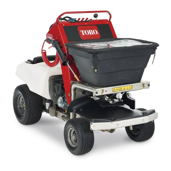
- Page 1 Form No. 3435-715 Rev A Stand-On E-Spreader/Sprayer Model No. 34230—Serial No. 400000000 and Up *3435-715* A Register at www.Toro.com. Original Instructions (EN)
- Page 2 Section 4442 or 4443 to use or operate the engine on additional information, contact an Authorized Service any forest-covered, brush-covered, or grass-covered Dealer or Toro Customer Service and have the model land unless the engine is equipped with a spark and serial numbers of your product ready.
-
Page 3: Table Of Contents
Contents Checking the Air Pressure in the Tires....68 Torqueing the Axle Bolts and Lug Nuts .............. 68 Safety ............... 4 Aligning the Front Wheels......... 68 Safety-Alert Symbol..........4 Servicing the Transaxle ........70 General Safety ........... 4 Controls System Maintenance ......70 Safety and Instructional Decals ...... -
Page 4: Safety
General Safety This machine is capable of amputating hands and feet and of throwing objects. Toro designed and tested this machine to offer reasonably safe service; however, failure to comply with safety instructions may result in injury or death. -
Page 5: Safety And Instructional Decals
Safety and Instructional Decals • Keep all safety signs legible. Remove all grease, dirt, and debris from safety signs and instructional labels. • Replace all worn, damaged, or missing safety signs. • When you install replacement components, ensure that current safety signs are affixed to those components. - Page 6 decal126-5186 126-5186 1. Read the Operator's Manual before servicing the machine 4. For more information on servicing the rear axle shafts, read or performing maintenance. the Operator's Manual. 2. Grease the steering pivots every 100 hours. 5. Check the tire pressure—90kPa (13 psi) every 50 hours. 3.
- Page 7 decal135-2844 135-2844 1. Fast 2. Slow 3. Neutral 4. Reverse 5. Warning-Read the Operator’s Manual. Do not operate this machine unless you are trained. Wear hearing protection. 6. Warning-Stay away from moving parts; keep all guards in place. Stop engine and remove key before adjusting, servicing, or cleaning.
- Page 8 decal135-7247 135-7247 1. Engine-Off 13. Spreader pattern control-rotate counterclockwise to unlock; rotate clockwise to lock. 2. Engine-On 14. Spread pattern control-pull handle up if heavy on left side. 3. Engine-Start 15. Spread pattern control-push handle down if heavy on right side.
-
Page 9: Setup
Setup Loose Parts Use the chart below to verify that all parts have been shipped. Procedure Description Qty. – No parts required Connect the battery. Media and Additional Parts Description Qty. Operator's Manual Read before operating the machine. Start the machine. Checking the Tire Air Checking the Pressure... -
Page 10: Connecting The Battery
Product Overview Connecting the Battery No Parts Required Procedure Remove the battery cover from the battery box (Figure g304841 Figure 4 1. Motion/steering control 5. Hopper 2. Engine/spreader—sprayer 6. Impeller controls 3. Spray wand 7. Sprayer nozzles 4. Hopper cover g027115 Figure 3 1. -
Page 11: Controls
Controls Parking-Brake Lever The parking-brake lever is located above the platform on the right side (Figure Machine Controls • To engage the parking brake, push the parking-brake lever down. Note: The brake lever engages a parking brake in the transaxle. •... -
Page 12: Engine Controls
Engine Controls The hour meter records the number of hours that the machine has operated. Hour meter time displays when the key is in the run position and the sprayer control switch is shut off. Fuel-Shutoff Valve The fuel-shutoff valve is located at the front, right side of the engine below the fuel tank (Figure Note:... -
Page 13: Spreader Controls
Spreader Controls Light Distribution Granular-Gate Lever The light distribution granular-gate lever is the fifth lever located at the top center of the control console (Figure 10). • To broadcast a narrow pattern of granular material, pull the light distribution granular-gate lever rearward fully to the limited O position. -
Page 14: Sprayer Controls
Sprayer Controls Spreader and Information Display The spreader and information display is located below the distribution impeller-gate levers at the bottom of the control console (Figure 10). The spreader and information display shows the following information: • The spreader controller firmware version •... - Page 15 Wide-Spray Pattern Lever Sprayer-Pump Switch The wide-spray pattern lever is located on the control The sprayer-pump switch is located to the left of the console (Figure 12). hour meter and spray pressure display, on the control console (Figure 12). • To turn O the sprayer in a wide-spray pattern (the right and left nozzles), pull the wide-spray pattern...
-
Page 16: Specifications
Specifications Use the sprayer-pump-supply valve to shut off the flow of liquid chemicals to the pump. Overall width 90 cm (35.5 inches) Overall length 171 cm (67.5 inches) Overall height 131 cm (51.5 inches) Weight sprayer tank and 227 kg (500 lb) hopper empty only hopper full 307 kg (676 lb) -
Page 17: Before Operation
If you are using more than 1 chemical, read the safely perform the job. Use only accessories and information about each chemical. Refuse to attachments approved by Toro. operate or work on the spreader-sprayer if this • Inspect the area where you will use the equipment, information is not available. -
Page 18: Performing Daily Maintenance
Fuel Safety • Gasoline is harmful or fatal if swallowed. Long-term exposure to vapors has caused cancer Use extreme care when handling fuel. in laboratory animals. Failure to use caution may cause serious injury or illness. In certain conditions gasoline is extremely flammable and its vapors are explosive. -
Page 19: Fuel Specification
Fuel tank capacity: 6.8 L (1.8 US gallons) this test, do not operate it. Contact your Note: Refueling the engine is difficult when using a authorized Toro distributor. larger refueling container such as a container with a • If the starter does not rotate the engine—the 19 L (5 US gal) capacity. -
Page 20: During Operation
During Operation overturn the machine or cause you to lose your balance or footing. – Do not operate the machine with damaged During Operation Safety guards, shields, or covers. Always have safety shields, guards, switches and other devices in place and working properly. General Safety –... - Page 21 – Keep children out of the working area and – Do not use the spray wand if the trigger lock is under the watchful care of another responsible damaged or missing. adult. – Do not keep the spray wand in the locked-open –...
-
Page 22: Operating The Machine
Operating the Machine Extending and Retracting the Operator’s Platform Extending the Operator’s Platform Pull the platform-lock knob inward until the pin of clears the upper hole in the chassis (Figure 18). g222400 Figure 17 1. Safe Zone — Use the machine here 2. - Page 23 Opening and Closing the Fuel Note: If the engine is warm , push down the choke lever to the O position. Shutoff Valve Rotate the ignition switch to the S position; TART Control fuel flow to the engine with the fuel shutoff refer to Ignition Switch (page 12).
- Page 24 Note: Note: Use this position during carburetor icing The machine moves faster the farther conditions: low outside air temperature with high you move the motion-control lever away from relative humidity. Symptoms include the engine the N position. EUTRAL runs rough at idle or low speed, and it discharges black or white smoke in the exhaust.
-
Page 25: Operating The Spreader
Using the Spreader and Information Display Spreader Screen Icons Spreader g020126 Figure 22 To turn left or right, move the steering control toward the desired turn direction. Motor Overcurrent Error Voltage Measurement Error To stop the machine, move the motion-control lever to the N position. - Page 26 Note: If the motor is run for eight seconds, the default screen displays. g305692 Figure 23 Spreader Firmware Screen g305328 Figure 26 Spreader Motor Screen Using the Impeller Control Switch g305693 Figure 24 Spreader Hours Screen g305645 Figure 27 Default Spreader Screen 1.
- Page 27 Calibrating the Spreader Place 6 additional pans, on each side, with no gap in between each pan (Figure 29). Calibrate the spreader each time you use a new material. The spreader broadcasts material in a pattern 1.5 to 6.7 m (5 to 22 ft) wide depending on the material particle size, volume/density, rate of travel, and wind conditions.
- Page 28 Determining the Distribution Pattern Go to the two corresponding pans. Starting from the outer edge, measure the distance between Set the spreader pattern control to the middle of left pan, across the center pan, to the outer edge its travel; refer to . of the right pan, and record the measurement.
- Page 29 Filling the Spreader Hopper Drive the spreader over the calibration course while applying the material. Maximum hopper weight capacity: 79 kg (175 lb) Empty the remaining material of the hopper into Drive the machine to the work site. a clean bucket; refer to Emptying the Spreader (page 30).
- Page 30 Emptying the Spreader Removing the Impeller Move the machine to a level surface, move motion-control lever to the N position, EUTRAL shut off the engine, wait for all moving parts to stop, remove key, and engage parking brake. Empty the hopper by scooping out as much of the material as possible.
- Page 31 Connecting the Rate-Gate Linkage Pull the linkage out until it clears the drop-rate (Figure 35). Move the heavy distribution granular-gate lever forward. Attaching the cable to the ball stud at the gate lever(Figure 35). Assembling the Impeller Assemble impeller onto the impeller shaft and secure the impeller with the drive pin.
- Page 32 Using the Spreader Spreading Charts Note: The cam setting tables for pellet material and the grass seed are provided with permission from the Brinly-Hardy Company; reference the Brinly-Hardy Company website for more information. Use these charts as an approximate guideline only. Other factors, such as weather conditions, spreader operation, and the condition of material affects spreader performance.
- Page 33 Cam Settings for Grass Seed Application (cont'd.) Type Bag Weight Coverage - m Cam Setting – Cam Setting – Spreader Width Full Rate Half Rate Mixtures Including 0.9 kg (2 lb) 93 (1,000) Coarse Seeds 1.81 kg (4 lb) 93 (1,000) 2.72 kg (6 lb) 93 (1,000) Rye Grasses or Tall...
- Page 34 Using the Deflector Gate Spreading Material Start the engine, and adjust the throttle midway Use the deflector-gate control to temporarily stop or between the S and the F positions deflect granular material away from sidewalks, parking (Figure 39). lots, patios, or anywhere the granular chemicals are not desired.
- Page 35 the light distribution granular-gate lever is in the position. g027497 Figure 40 1. Wide spreader 2. Narrow spreader pattern—variable effective pattern—variable effective width to 6.7 m (22 ft) width from 1.5 m (5 ft) maximum minimum Evaluate the spread pattern. Note: If you need to adjustment the spreading pattern, refer to...
- Page 36 Spreading Tips Important: Ensure that you calibrate the spreader before you start using it. g027374 Figure 41 Spreader path example 1. Narrow distribution-side deflector 4. Do not spread when turning 180° 7. Gate lowered 2. Forward 5. End of spreading job 3.
-
Page 37: Operating The Sprayer
Operating the Sprayer Using the Sprayer and Information Display CAUTION Sprayer Screen Icons Chemicals are hazardous and can cause personal injury. • Read the chemical manufacturer’s directions on the label before handling the chemicals; follow all manufacturer recommendations and precautions. Sprayer Hour meter •... - Page 38 g305694 g305697 Figure 42 Figure 45 Sprayer Firmware Screen Battery Voltage Screen Default Sprayer Screen The default sprayer screen (Figure 46) displays after the start-up screens display. The hour meter records engine hours when the hourglass symbol flashes. After you turn the key to the O position, the display shuts off after 3 seconds.
- Page 39 Sprayer Operation Screen • Tap the bottom of the sprayer-pump switch to lower spray-system pressure. The sprayer operation screen (Figure 47) displays • Push the bottom of the sprayer-pump switch for when you tap the sprayer-pump switch. 1-second to shutoff the spray pump. Calibrating the Sprayer Note: Before you use the sprayer for the first time...
- Page 40 shut off the engine, wait for all moving parts to stop, remove key, and engage parking brake. Average the 3 test run times (in seconds); use the average course time formula. Record the average course speed here: Average Course Time Formula (time 1) + (time Formula 2) + (time 3)
- Page 41 Testing the Sprayer Nozzle Discharge Collection Worksheet Left sprayer Center sprayer Right sprayer Operator supplied equipment: Have a stop watch nozzle nozzle nozzle capable of measuring ± 1/10 second and a container graduated in 50 ml (1 fl oz) increments. Test ml (fl oz) ml (fl oz)
- Page 42 Red Nozzle Table Right nozzle—record the converted collected-water quantity here: Spray Single Nozzle Rate Pressure Center nozzle—record the converted collected-water quantity here: 0.7 Bar 0.77 L/min 0.20 gpm 26 oz/min Left nozzle—record the converted (10 psi) collected-water quantity here: Calculate the flow rate of each nozzle using the 1.4 Bar 1.06 L/min 0.28 gpm...
- Page 43 Gray Nozzle Table Blue Nozzle Table Spray Spray Single Nozzle Rate Single Nozzle Rate Pressure Pressure 0.7 Bar 1.12 L/min 0.30 gpm 38 oz/min 0.7 Bar 1.89 L/min 0.50 gpm 64 oz/min (10 psi) (10 psi) 1.4 Bar 1.60 L/min 0.42 gpm 54 oz/min 1.4 Bar...
- Page 44 Using the Sprayer 1.563 L/100 m (1.5 2.99 Lpm x 2 x 6 qt/1,000 ft 8.369 kph x 2.743 m Before Operating the Sprayer Some chemicals are more aggressive than others Liter per Hectar Application Rate and each chemical interacts differently with various materials.
- Page 45 Start the engine and set the throttle midway between the S and F positions. Set the sprayer-pump switch to the O position (Figure 54). g305521 Figure 54 1. Agitation-bypass lever 4. Hour meter and spray g027391 pressure display Figure 52 2.
- Page 46 moving parts to stop, remove key, and engage tank. For the agitation feature to work, set the parking brake. sprayer-pump switch to the O position, pull back the tank-agitation lever, and run the engine at high Remove the plug from the drain valve for the idle.
- Page 47 g027299 Figure 57 Wide-spray pattern 1. Overlap area 2. Effective spray area When you finish spraying, push forward the spray-pattern levers and set the sprayer-pump switch to the O position. Note: If you need to continue to mix the sprayer tank contents, leave the sprayer-pump switch in the O position, and pull the tank-agitation lever.
- Page 48 Spraying Tips g027300 Figure 58 1. Overlap area—narrow spray pattern 6. Sprayer Off—do not spray when turning the machine 180° 2. Effective spray area 7. End of spraying job 3. Forward 8. Property fence 4. Overlap area—wide spray pattern 9. Gate 5.
-
Page 49: After Operation
Spraying with the Spray Wand Adjust the pump pressure to the spray wand perform the following: WARNING • To increase the pump pressure to the wand, rotate the wand-pressure control The spray wand traps liquids under counterclockwise (Figure 60). high pressure, even when engine is off. High-pressure spray discharge could cause serious injury or death. -
Page 50: Cleaning And Lubricating The Spreader
remove the key or disconnect the spark-plug wire. Wait for all movement to stop before adjusting, cleaning or repairing the machine. • Clean the machine as stated in Cleaning and Lubricating the Spreader (page 50) Cleaning the Sprayer (page 51) •... -
Page 51: Cleaning The Sprayer
Cleaning the Sprayer Cleaning the Sprayer System and Wand Service Interval: After each use Important: Always empty and clean the sprayer WARNING immediately after each use. Failure to do so may cause the chemicals to dry or thicken in the lines, Swallowing or inhaling chemicals could cause clogging the pump and other components. - Page 52 Cleaning the Strainer Service Interval: After each use Important: If you used wettable-powder chemicals, clean the strainer after each time that you rinse the sprayer tank. Empty the sprayer tank; refer to Emptying the Sprayer Tank (page 45). Rotate the handle of the pump-shutoff valve 90° counterclockwise to the position (Figure...
-
Page 53: Transporting The Machine
Cleaning the Sprayer Nozzle Transporting the Machine Service Interval: After each use Machine weight: 227 kg (500 lb)—both sprayer tank and hopper empty; 389 kg (857 lb)—both sprayer Rotate the nozzle cap 90° counterclockwise and tank and hopper full remove the cap from the nozzle body (Figure 66). - Page 54 If using a trailer, connect it to the towing vehicle Use the tie-down points on the machine to and connect the safety chains. securely bind the machine to the trailer or truck with straps, chains, cable, or ropes (Figure 68). If applicable, connect the trailer brakes.
-
Page 55: Maintenance
Maintenance Maintenance Safety could be dangerous. The mechanical or hydraulic jacks may not be enough support or may • While performing maintenance on the machine, malfunction, allowing the machine to fall and cause someone could start the engine. Accidental possible injury. Do not rely solely on mechanical starting of the engine could seriously injure you or or hydraulic jacks for support. -
Page 56: Recommended Maintenance Schedule(S)
Recommended Maintenance Schedule(s) Maintenance Service Maintenance Procedure Interval • Change the engine oil. After the first 10 hours • Check the safety interlock system. • Test the starter interlock. • Check air cleaner; replace if dirty (more often under severe conditions). Before each use or daily •... -
Page 57: Pre-Maintenance Procedures
Pre-Maintenance Lubrication Procedures Lubricating the Grease Fittings Preparing the Machine Service Interval: Every 100 hours WARNING Grease type: National Lubricating Grease Institute While you are maintaining or adjusting the (NGLI) grade No. 2 multi-purpose gun grease. machine, someone could start the engine. Prepare the machine for maintenance;... -
Page 58: Engine Maintenance
3. Air-filter element Engine Oil Specification 2. Foam pre-cleaner 4. Air-filter base Oil Type: Toro 4-Cycle Premium Engine Oil or a high-quality detergent oil (including synthetic) API service SJ or higher Cleaning the Foam Filter Element Oil viscosity: Refer to the table below. -
Page 59: Checking The Engine-Oil Level
Insert the dipstick from the engine as shown in Figure Note: Do not thread the dipstick into the filler neck when checking the engine oil level. g023796 Figure 73 Checking the Engine-Oil Level Service Interval: Before each use or daily g257927 Figure 76 1. - Page 60 Align a drain pan with a capacity of 1.5 L (1.6 US qt) or greater below the drain valve at the bottom of the skid plate and inboard from the battery tray (Figure 77). g257928 Figure 78 g258081 1. Dipstick 2.
-
Page 61: Servicing The Spark Plug
Hand tighten the dipstick into the filler neck (Figure 78). Servicing the Spark Plug Spark Plug Specification Spark plug type: Champion® RC12YC, Kohler® 12 g008794 Figure 81 132 02-S, or Kohler 25 132 14-S (RFI compliant) Removing the Spark Plug Installing the Spark Plug Tighten the spark plug as follows: Prepare the machine for maintenance;... -
Page 62: Fuel System Maintenance
Fuel System Remove the screws that secure the heat shield to the muffler, and remove the heat shield Maintenance (Figure 84). Draining the Fuel System Close the fuel-shutoff valve; refer to Opening and Closing the Fuel Shutoff Valve (page 23). Locate the drain bolt that is in the side port of the carburetor bowl (Figure... -
Page 63: Electrical System Maintenance
Electrical System Maintenance Servicing the Battery Service Interval: Monthly Always keep the battery clean and fully charged. Use a paper towel to clean the battery case. If the battery terminals are corroded, clean them with a solution of 4 parts water and 1 part baking soda. Apply a light coating of grease to the battery terminals to prevent corrosion. - Page 64 Checking the Battery Charge setting and charging interval recommended to charge the battery to 12.6 V or greater; refer to the battery charge table below. CAUTION Important: Ensure that the negative battery If the ignition is in the O position, there cable is disconnected, and the battery is potential for sparks and for engine charger used for charging the battery...
-
Page 65: Removing And Installing The Battery
Charging the Battery Removing and Installing the Battery WARNING Charging the battery produces gasses that Removing the Battery can explode. Never smoke near the battery and keep sparks WARNING and flames away from battery. Battery terminals or metal tools could short against metal machine components, causing Important: Always keep the battery fully charged... -
Page 66: Jump-Starting The Machine
Jump-Starting the Machine DANGER Jump-starting a battery that is cracked, frozen, has low electrolyte level, or an open/shorted battery cell can cause an explosion, resulting in serious personal injury. Do not jump-start a battery if these conditions exist; replace the battery. g027432 Figure 89 1. -
Page 67: Servicing The Fuses
Note: The positive battery cable is wired to the starter or solenoid. g306403 g012785 Figure 90 1. Positive (+) cable on the discharged battery 2. Positive (+) cable on booster battery 3. Negative (–) cable on the booster battery 4. Negative (–) cable on the engine block 5. -
Page 68: Drive System Maintenance
Drive System Prepare the machine for maintenance; refer to Preparing the Machine (page 57). Maintenance Check the tire pressure; refer to Checking the Air Pressure in the Tires (page 68). Center and secure the steering control by Checking the Air Pressure aligning 2 bolts (5/16 x 3 inch) through the outside holes on the steering control and through in the Tires... - Page 69 Note: The front measurement should be 6.4 to Align the holes in the front cover with the 12.7 mm (1/4 to 1/2 inch) larger than the rear clip nuts in the chassis and secure the cover measurement. with the 4 thumb nuts that you removed in If the front measurement is smaller than 6.4 mm (1/4 inch) or larger than 12.7 mm (1/2 inch), Remove the bolts that you installed in step...
-
Page 70: Servicing The Transaxle
Servicing the Transaxle Controls System Maintenance Service Interval: Every 50 hours Transaxle Oil Type: Toro® HYPR-OIL™ 500 hydraulic oil or Mobil® 1 15W-50 Adjusting the Pattern Prepare the machine for maintenance; refer to Control Cable for the Preparing the Machine (page 57). -
Page 71: Maintaining The Chassis
Maintaining the Chassis Checking the Machine for Loose Hardware Service Interval: Before each use or daily Prepare the machine for maintenance; refer to Preparing the Machine (page 57). Visually inspect machine for damaged or worn parts, and check for loose hardware. Note: Before operating the machine, replace any damaged parts and tighten all loose... -
Page 72: Maintaining The Sprayer System
Maintaining the Sprayer Cleaning System Cleaning the Engine and the Exhaust System Area Checking Sprayer System Service Interval: After each use (may be required Service Interval: Every 50 hours more often in dry or dirty conditions.) Prepare the machine for maintenance; refer to Preparing the Machine (page 57). -
Page 73: Waste Disposal
Storage Install the cooling shrouds onto the engine. Note: Operating the engine without cooling Set sprayer-pump switch to the O position, shrouds will cause engine damage due to stop the machine, move motion-control lever to overheating. the N position, shut off the engine, wait EUTRAL for all moving parts to stop, remove key, and Waste Disposal... - Page 74 Start the machine and set sprayer-pump switch to the O position Push the tank-agitation lever to the O position. Pull the narrow-spray pattern lever. Note: Run the sprayer nozzle until the narrow nozzle is spraying air. Push the narrow-spray pattern lever and pull back the wide-spray pattern lever.
-
Page 75: Troubleshooting
Troubleshooting Important: Ensure that the operator safety mechanisms for the machine are connected and in proper operating condition before you use the machine. When a problem occurs, do not overlook the simple causes. For example, starting problems could be caused by an empty fuel tank. -
Page 76: Sprayer Fault Codes
Spreader Fault Code Table (cont'd.) Motor Wire !05 The motor wire fault code !05 displays if the sprayer controller cannot sense the load circuits (O 1 or O 2) between the sprayer and information display and the motor. • Fault code !05 displays in the sprayer and information display. •... - Page 77 Sprayer Fault Code Table (cont'd.) Motor Overcurrent !02 The motor overcurrent fault code !02 displays if the motor load circuit draws too much current. Check the motor and inspect it for damage and wear. • Fault code !02 displays in the sprayer and information display. •...
- Page 78 Troubleshooting the Speader and Sprayer Controllers Problem Possible Cause Corrective Action The spreader information display or 1. The spreader controller or the sprayer 1. Spreader—check impeller and hopper controller detects excessive electrical sprayer information display shows fault for obstructions that may add an core !02.
- Page 79 Troubleshooting the Machine Problem Possible Cause Corrective Action The starter does not rotate the engine. 1. The parking brake is not engaged. 1. Engage the parking brake. 2. The battery does not have a full 2. Charge the battery; refer to the charge.
- Page 80 Problem Possible Cause Corrective Action The engine overheats. 1. The engine load is excessive. 1. Reduce the ground speed of the machine. 2. The oil level in the engine is low. 2. Add oil into the engine to the proper oil level.
- Page 81 Problem Possible Cause Corrective Action There is no spray from the sprayer nozzles 1. The sprayer tank is empty. 1. Fill the sprayer tank. in the boom or the nozzles have poor 2. The sprayer-pump supply valve is 2. Fully open the sprayer-pump supply output.
-
Page 82: Schematics
Schematics g305771 Electrical Schematic 135-6127 (Rev. C) - Page 83 g305820 Sprayer System Schematic (Rev. A)
- Page 84 Notes:...
- Page 85 Notes:...
- Page 86 Notes:...
- Page 87 While the exposure from Toro products may be negligible or well within the “no significant risk” range, out of an abundance of caution, Toro has elected to provide the Prop 65 warnings. Moreover, if Toro does not provide these warnings, it could be sued by the State of California or by private parties seeking to enforce Prop 65 and subject to substantial penalties.