Table of Contents
Advertisement
Quick Links
Download this manual
See also:
Operator's Manual
Advertisement
Table of Contents

Related Manuals for Toro 34215


Summary of Contents for Toro 34215
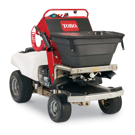
- Page 1 Form No. 3395-328 Rev A Stand-On Spreader Sprayer Model No. 34215—Serial No. 315000001 and Up *3395-328* A Register at www.Toro.com. Original Instructions (EN)
- Page 2 You are responsible for operating the product properly and safely. You may contact Toro directly at www.Toro.com for product safety and operation training materials, accessory information, help finding a dealer, or to register your product.
-
Page 3: Table Of Contents
Cleaning the Debris from the Machine.......66 Safety ................4 Waste Disposal............66 Safe Operating Practices........... 4 Storage ................66 Toro Spreader Sprayer Safety ........7 Preparing the Machine for Extended or Winter Slope Indicator ............9 Storage..............66 Safety and Instructional Decals ........10 Troubleshooting ............68... -
Page 4: Safety
Operator’s Manual . Modifications to this machine should only be exposure. made by either the manufacturer or an Authorized Toro Wear hearing protection when operating this Dealer. machine. - Page 5 • • Check all sprayer components for wear and leaks before Do not fill, calibrate, or clean the unit when people, applying pressure to the system. Do not use the sprayer especially children, or pets are in the area. if it is leaking or damaged. •...
- Page 6 • Do not change the engine governor setting or overspeed WARNING the engine. Hands, feet, hair, clothing, or accessories can • Stop the machine after striking objects or if an abnormal become entangled in rotating parts. Contact with vibration occurs. Make the necessary repairs before the rotating parts can cause traumatic amputation resuming operations.
-
Page 7: Toro Spreader Sprayer Safety
Toro Spreader Sprayer Safety • Stop spreading/spraying when making tight turns to minimize uneven distribution pattern, application rate, The following list contains safety information specific to Toro and chemical drift. products and other safety information you must know. • Chemicals may drift and cause injury to people and animals;... - Page 8 To best protect your investment and maintain optimal performance of your Toro equipment, count on Toro genuine parts. When it comes to reliability, Toro delivers replacement parts designed to the exact engineering specifications of our equipment. For peace of mind, insist on Toro genuine parts.
-
Page 9: Slope Indicator
Slope Indicator G011841 Figure 3 This page may be copied for personal use. 1. The maximum slope you can safely operate the machine on is 15 degrees. Use the slope chart to determine the degree of slope of hills before operating. Do not operate this machine on a slope greater than 15 degrees. Fold along the appropriate line to match the recommended slope. -
Page 10: Safety And Instructional Decals
Safety and Instructional Decals Safety decals and instructions are easily visible to the operator and are located near any area of potential danger. Replace any decal that is damaged or lost. 117–2718 126-2620 126-2621 1. Pull lever up to disengage 2. - Page 11 126-2195 1. Hour meter 14. Spray pressure-Decrease 2. Engine-Off 15. Spray pressure-Increase 3. Engine-On 16. Spray wand flow valve 4. Engine-Start 17. Spray wand flow-Off 5. Granular side deflector control-Pull up to raise. 18. Spray wand flow-Decrease 6. Granular side deflector control-Push down to lower. 19.
- Page 12 126-2612 1. Fast 9. Thrown object hazard-do not operate when people and pets are in the area. 2. Slow 10. Warning-do hot operate on slopes greater than 15 degrees. Do not operate on wet slopes–use extreme caution when operating on slopes; operate across slopes not up and down. Loads may shift on slopes or when turning.
- Page 13 126-5186 1. Read the Operator's Manual before servicing the machine 4. For more information on servicing the rear axle shafts, read or performing maintenance. the Operator's Manual. 2. Grease the steering pivots every 100 hours. 5. Check the tire pressure—90kPa (13 psi) every 50 hours. 3.
-
Page 14: Setup
Procedure Front and Rear Tire Air Pressure: 83 to 97 kPa (12 to 14 psi) Transaxle Oil Type: Toro® HYPR-OIL™ 500 hydraulic oil 1. Check the air pressure in the front and rear tires. or Mobil® 1 15W-50 2. If the air pressure in the tires need adjustment, inflate The Transaxle is shipped with oil;... -
Page 15: Connecting The Battery
Product Overview Connecting the Battery No Parts Required Procedure 1. Remove the battery cover from the battery box (Figure Figure 5 1. Motion/steering control 5. Hopper 2. Engine/spreader–sprayer 6. Impeller controls 3. Spray wand 7. Sprayer nozzles 4. Hopper cover Figure 4 1. -
Page 16: Controls
Controls Machine Controls Steering Control The steering control is located behind the control console (see Figure • Move the steering control to the right or left to steer the machine to the right or left respectively. • Moving the steering control to the center allows the machine to steer straight. -
Page 17: Spreader Controls
Fuel Shut-Off Valve transporting the machine, set the parking brake and bind the machine to the transport vehicle. The fuel shutoff valve is located at the front right side of the engine below the fuel tank (Figure Drive Wheel Release Lever Note: Close the fuel shut-off valve when the machine is not The drive wheel release lever is located above the platform at used for a few days, during transport to and from the job site,... - Page 18 Spreader Pattern Control Impeller On/Off Switch The spreader pattern control is located to the right of the The impeller On/Off switch is located below the deflector gate control at the control console (Figure 11). impeller-distribution flow-rate knob at the bottom of the control console (Figure 11).
-
Page 19: Sprayer Controls
Sprayer Controls Narrow Spray Pattern Lever The narrow spray pattern lever is the second lever, located at the top center of the control console, to the right of the tank agitation lever (Figure 13). • Pull the narrow spray pattern lever toward you to turn on the sprayer in a narrow spray pattern (the center nozzle only). -
Page 20: Specifications
Figure 14 1. Trigger 3. Spray wand handle 2. Trigger lock Tank Drain Valve Figure 16 The tank drain valve is located at the left side and under the 1. Sprayer tank 3. Handle (open position) sprayer tank (Figure 16). 2. -
Page 21: Operation
Operation Note: Determine the left and right sides of the machine from the normal operating position. Checking the Engine-Oil Level Service Interval: Before each use or daily Oil Type: Detergent oil (API service SJ or higher) Oil viscosity: Refer to the table below. Figure 18 1. -
Page 22: Adding Fuel
Adding Fuel DANGER In certain conditions during fueling, static Fuel tank capacity: 6.1 L (1.6 US gallons) electricity can be released causing a spark which • For best results, use only clean, fresh (less than 30 days can ignite the gasoline vapors. A fire or explosion old), unleaded gasoline with an octane rating of 87 or from gasoline can burn you and others and can higher ((R+M)/2 rating method). -
Page 23: Checking The Safety Interlock System
• a funnel machine—the machine does not pass this test, 1. Clean around the fuel tank cap. do not operate it. Contact your authorized Toro service distributor. 2. Remove the cap from the tank. • If the starter does not rotate the engine—the 3. -
Page 24: Operating The Machine
Operating the Machine Opening and Closing the Fuel Shut-off Valve Extending and Retracting the Control fuel flow to the engine with the fuel shutoff valve Operator’s Platform as follows: • Rotate the handle for the fuel-shutoff valve 90 degrees Extending the Operator’s Platform clockwise to the open the valve. -
Page 25: Stopping The Engine
Driving the Machine 5. Rotate the ignition switch to the Start position; refer to Ignition Switch (page 16). CAUTION Note: Release the switch as soon as the engine starts. Machine can turn rapidly by moving the steering Important: Do not crank the engine continuously control to the far right or left. -
Page 26: Operating The Spreader
Operating the Spreader Note: Stopping distance may vary depending on the spreader-sprayer load. CAUTION Note: When you release the motion control lever, it automatically returns to the Neutral position. Chemicals are hazardous and can cause personal injury. Driving the Machine in Reverse •... - Page 27 Calibrating the Spreader Place six additional pans, on each side, with no gap in between each pan (Figure 24). Calibrate the spreader each time a new material is used. The spreader can broadcast material in a pattern 1.5 to 6.7 m (5 to 22 ft) wide depending on the material particle size, volume/density, and rate of travel, and wind.
- Page 28 12. To adjust the spreader pattern, refer to the Adjusting 4. Add material to the hopper (for example, add 11.3 kg the Spreader Pattern (page 32). (25 lb) add of material). 13. Repeat steps through until an uniform pattern is 5.
- Page 29 Figure 26 1. Forward cover 3. Thumb screw 2. Clip nut 4. Remove the drive pin that secure the impeller to the shaft of the impeller motor and remove the impeller from the shaft (Figure 27 Figure 28). Figure 25 1.
- Page 30 Figure 28 5. Place a shallow pan under the shaft of the impeller motor (Figure 28). 6. Open the hopper gate as follows: A. Push the locking sleeve for the gate cable rearward and lift the cable up from the ball stud of the rate gate linkage (Figure 29).
- Page 31 Spreading Charts Note: The cam setting tables for pellet material and the grass seed are provided with permission from the Brinly-Hardy Company; reference the Brinly-Hardy Company website for more information. These charts are to be used as an approximate guideline only. Other factors, such as weather conditions, spreader operation, and condition of materials, will affect your results.
- Page 32 Cam Settings for Grass Seed Application (cont'd.) Type Bag Weight Coverage - m Cam Setting – Cam Setting – Spreader Width Full Rate Half Rate Rye Grasses or Tall 0.9 kg (2 lb) 93 (1,000) Fescue 1.81 kg (4 lb) 93 (1,000) 7.75 2.72 kg (6 lb)
- Page 33 Using the Deflector Gate Use the deflector gate control to temporarily stop or deflect granular material away from sidewalks, parking lots, patios, or anywhere granular chemicals are not desired. Note: The deflector gate changes the discharged of materials from the left side of the spreader only. Push the knob for the deflector gate control down to lower the deflector and temporarily deflect the granular material.
- Page 34 Spreading Tips Figure 33 Spreader path example 1. Narrow distribution-side deflector lowered 5. End of spreading job 2. Forward 6. Property fence 3. Effective spreading width—variable 1.5 to 6.7 m (5 to 22 ft) 7. Gate 4. Do not spread when turning 180 degrees •...
- Page 35 Note: The indicator light above the impeller On/Off switch will flash at a constant rate. Note: As long as the impeller speed control is locked (indicated by the flashing indicator light) the impeller motor will start and run at the last locked speed.
-
Page 36: Operating The Sprayer
Note: Do not use a power washer to clean the machine. The high pressure water may force residual corrosive materials into spreader-spreader components. Note: Tilt the screen at the bottom of the hopper forward to clean the bottom components of hopper. Figure 38 Operating the Sprayer CAUTION... -
Page 37: Calibrating The Sprayer
Calibrating the Sprayer Record your the average course speed here Note: Before you use the sprayer for the first time or change the nozzles or when the sprayer is out of Average Course Time Formula adjustment—calibrate the sprayer for ground speed and flow time 1 + time rate. - Page 38 Testing the Sprayer Nozzle Discharge Operator supplied equipment: Stop watch capable of measuring ± 1/10 second and a container graduated in 50 ml (1 fl-oz) increments. Note: Ensure that there is enough clean water in the tank to complete the calibration. 1.
- Page 39 Collection Worksheet B. Record the converted quantity of water collected for the center nozzle here Left sprayer Center sprayer Right sprayer nozzle nozzle nozzle C. Record the converted quantity of Test ml (fl-oz) ml (fl-oz) ml (fl-oz) water collected for the left nozzle here Test ml (fl-oz) ml (fl-oz)
- Page 40 Center Nozzle—Narrow Pattern (red) 1.563 L/100 m (1.5 2.99 Lpm x 2 x 6 (cont'd.) qt/1,000 ft 8.369 kph x 2.743 m Liter per Hectar Application Rate 2.1 bar 1331 1.32 L (0.35 1.19 to 1.45 L (0.32 (30 psi) ml (45 US gallon) to 0.39 US gallon)
- Page 41 Using the Sprayer Before Operating the Sprayer Some chemicals are more aggressive than others and each chemical interacts differently with various materials. Some consistencies of sprayer chemicals (e.g. wettable powders, charcoal) are more abrasive and lead to higher wear rates. If a chemical is available in a formulation that would provide increased life to the sprayer, use this alternative formulation.
- Page 42 Note: The drain valve is located at the left side of the 7. Start the engine and set the throttle midway between the Slow and Fast positions. machine. 8. Set the sprayer pump switch to the On position (Figure 44). Figure 45 1.
- Page 43 the chemicals to dry or thicken in the lines, clogging the 10. Release the trigger for the wand and return it to the pump and other components. holder on the machine (Figure 11. Move the spray pattern levers forward to the Off Clean the spray system after each spraying session.
- Page 44 Cleaning the Sprayer Nozzle 4. Rotate the strainer bowl counterclockwise and remove the bowl and screen from the body of the strainer Service Interval: After each use (Figure 48). 1. Rotate the nozzle cap 90° counterclockwise and Note: Remove the strainer bowl by hand. remove the cap from the nozzle body (Figure 49).
- Page 45 Spraying with the Sprayer Boom Important: In order to ensure that your chemical solution remains well mixed, use the agitation feature whenever you have solution in the tank. For the agitation feature to work, set the sprayer pump switch to the On position, pull back the tank agitation lever, and run the engine at high idle.
- Page 46 Spraying Tips Figure 52 1. Overlap area (narrow spray pattern) 6. Sprayer Off (do not spray when turning the machine 180°) 2. Effective spray area 7. End of spraying job 3. Forward 8. Property fence 4. Overlap area (wide spray pattern) 9.
-
Page 47: Transporting The Machine
Spraying with the Spray Wand WARNING The spray wand traps liquids under high pressure, even when engine is off. High pressure spray discharge could cause serious injury or death. • Keep clear of nozzle and do not direct the spray or stream from the wand at people, pets, or Figure 54 non-work area property. - Page 48 Loading the Machine onto a Transport Vehicle WARNING Loading the machine onto a trailer or truck increases the possibility of backward tip-over, and could cause serious injury or death. • Use extreme caution when operating a machine on a ramp. •...
- Page 49 5. Stop the engine, remove the key, set the brake, and close the fuel valve. 6. Set the parking brake and block the tires. 7. Use the tie-down points on the machine to securely bind the machine to the trailer or truck with straps, chains, cable, or ropes (Figure 55).
-
Page 50: Maintenance
Maintenance WARNING WARNING While you are maintaining or adjusting the machine, The engine can become very hot. Touching a hot someone could start the engine. Accidentally engine can cause severe burns. starting the engine could seriously injure you or Allow the engine to cool completely before service other bystanders. -
Page 51: Premaintenance Procedures
Premaintenance Lubrication Procedures Lubricating the Grease Fittings CAUTION Service Interval: Every 100 hours Raising the machine for service or maintenance Grease type: National Lubricating Grease Institute (NGLI) relying solely on mechanical or hydraulic jacks grade #2 multi-purpose gun grease. could be dangerous. The mechanical or hydraulic Note: Refer to the lubrication chart for the grease points jacks may not be enough support or may and service intervals. -
Page 52: Engine Maintenance
Engine Maintenance Note: Inspect the paper and foam filter elements for damage or an excessive accumulation of dirt. Replace all damaged filters. Clean the foam filter element if it is Servicing the Air Cleaner dirty. Replace the paper filter element if it is dirty. Service Interval: Before each use or daily Servicing the Foam Filter Element Every 100 hours... -
Page 53: Servicing The Engine Oil
Servicing the Engine Oil Oil Type: Detergent oil (API service SJ or higher) Engine Oil Capacity: 1.1 L (1.2 US qt) Oil viscosity: Refer to the table below. Figure 60 1. Drain valve 4. Skid plate 2. Hex-head stem 5. Front of the machine 3. -
Page 54: Servicing The Spark Plug
Servicing the Spark Plug 9. Insert the dipstick from the engine as shown in Figure Service Interval: Every 100 hours Note: Do not thread the dipstick into the filler neck Spark Plug Type: NGK BR6HS, Champion RTL86C, or when checking the engine oil level. equivalent Air Gap: 0.6 to 0.7 mm (0.02 to 0.03 inch) Make sure the air gap between the center and side electrodes... -
Page 55: Servicing The Engine Fuel System
Checking the Spark Plug Important: Do not clean the spark plug(s). Always replace the spark plug(s) when it has a black coating, worn electrodes, an oily film, or cracks. If you see light brown or gray on the insulator, the engine is operating properly. - Page 56 Figure 69 1. Fuel hose 3. Strainer 2. Boss 4. Fuel tank Figure 67 1. Fuel tank 5. Tank supports Cleaning the Fuel Strainer 2. Strainer 6. Bolt 6 x 25 mm 1. Loosen the hose clamp and disconnect fuel hose from 3.
-
Page 57: Servicing The Spark Arrester
8. Add fuel to the fuel tank, open the fuel shutoff valve, and check for fuel leaks. Note: Do not add too much fuel to the tank before you have confirmed that there are no fuel leaks. Servicing the Spark Arrester Service Interval: Every 200 hours Removing the Spark Arrester WARNING... -
Page 58: Electrical System Maintenance
Checking the Battery Charge Electrical System Maintenance CAUTION If the ignition is in the On position there is potential for sparks and engagement of components. Sparks Servicing the Battery could cause an explosion or moving parts could Service Interval: Monthly accidentally engage causing personal injury. -
Page 59: Removing And Installing The Battery
Important: Make sure that the negative battery 3. Ensure that the filler caps are installed on the battery. cable is disconnected and the battery charger used 4. Charge the battery for 1 hour at 25 to 30 amps or 6 for charging the battery has an output of 16 volts hours at 4 to 6 amps. -
Page 60: Jump Starting The Machine
Installing the Battery WARNING 1. Place the battery into the battery box. Incorrect battery-cable routing could damage the 2. Position the battery and battery box onto the battery machine and cables causing sparks. Sparks can tray of the machine. cause the battery gasses to explode, resulting in personal injury. -
Page 61: Servicing The Fuses
Note: The following instructions are adapted from the 8. Start the machine and remove the cables in the reverse SAE J1494 Rev. Dec. 2001 – Battery Booster Cables – order of connection (disconnecting the engine block Surface Vehicle Recommended Practice (SAE – Society of (black) connection first). -
Page 62: Drive System Maintenance
Drive System 3. Center and secure the steering control by aligning 2 bolts 9 x 76 mm (5/16 x 3 inch) through the outside Maintenance holes on the steering control and through the control column. Checking the Air Pressure in the Tires Service Interval: Every 50 hours Note: Both the front and rear tires need to be inflated. -
Page 63: Servicing The Transaxle
Service Interval: Every 50 hours rod ends for the steering linkage as follows: A. Remove the 4 thumb screws that secure the front Transaxle Oil Type: Toro® HYPR-OIL™ 500 hydraulic oil cover (below the is below the impeller) to the or Mobil® 1 15W-50... -
Page 64: Controls System Maintenance
Controls System Maintenance Adjusting the Pattern Control Cable for the Spreader 1. Stop the engine, set the parking brake, remove the key, and wait for all moving parts to stop before leaving the operating position. 2. Empty the hopper; refer to Emptying the Hopper (page 29) 3. -
Page 65: Maintaining The Sprayer System
Maintaining the Sprayer Cleaning System Cleaning the Engine and the Exhaust System Area Check Sprayer System Service Interval: Before each use or daily (may be required Service Interval: Every 50 hours more often in dry or dirty conditions.) 1. Stop the engine, set the parking brake, remove the key, and wait for all moving parts to stop before leaving the CAUTION operating position. -
Page 66: Cleaning The Debris From The Machine
Cleaning the Debris from the Storage Machine 1. Set sprayer pump switch to the Off position, stop the machine, shut off the engine, set the parking brake, and Service Interval: Before each use or daily remove the key. 1. Stop the engine, set the parking brake, remove the key, 2. - Page 67 Note: Run the sprayer nozzle until the narrow nozzle is spraying air. E. Push forward the narrow-spray pattern lever and pull back the wide-spray pattern lever. Note: Run the sprayer nozzles until the both wide nozzles are spraying air. F. Push forward the wide-spray pattern lever. 3.
-
Page 68: Troubleshooting
Troubleshooting Important: It is essential that the operator safety mechanisms for the machine are connected and in proper operating condition before you use the machine. When a problem occurs, do not overlook the simple causes. For example: starting problems could be caused by an empty fuel tank. - Page 69 Problem Possible Cause Corrective Action The engine loses power. 1. The engine load is excessive. 1. Reduce the ground speed of the machine. 2. The air filter elements are dirty. 2. Clean the foam filter element or replace the paper filter element. 3.
- Page 70 Problem Possible Cause Corrective Action The spreader or sprayer pattern is uneven. 1. The impeller is dirty or damaged. 1. Clean, repair, or replace impeller. 2. The spreader pattern control is not 2. Adjust the spreader pattern control; adjusted properly. refer to the Adjust the Spreader Pattern procedure in the Using the Spreader section.
- Page 71 Problem Possible Cause Corrective Action The indicator light above the impeller 1. The indicator light is flashing at a slow, 1. While the impeller motor is running, On/Off switch is illuminated or flashing. constant rate and the —impeller motor press and hold the impeller On/Off speed is not adjustable (locked).
-
Page 72: Schematics
Schematics Electrical Schematic (Rev. A) - Page 73 Electrical Diagram (Rev. A)
- Page 74 Sprayer System Schematic (Rev. A)
- Page 75 Notes:...
- Page 76 Toro importer. If all other remedies fail, you may contact us at Toro Warranty Company. Australian Consumer Law: Australian customers will find details relating to the Australian Consumer Law either inside the box or at your local Toro Dealer.