
Related Manuals for Toro 34215


Summary of Contents for Toro 34215
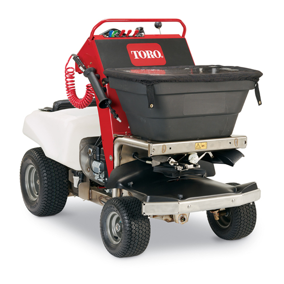
- Page 1 Form No. 3402-994 Rev A Stand-On Spreader/Sprayer Model No. 34215—Serial No. 316000001 and Up *3402-994* A Register at www.Toro.com. Original Instructions (EN)
- Page 2 You are responsible for operating the product properly and safely. You may contact Toro directly at www.Toro.com for product safety and operation training materials, accessory information, help finding a dealer, or to register your product.
-
Page 3: Table Of Contents
Cleaning the Debris from the Machine.......63 Safety ................4 Waste Disposal............64 Safe Operating Practices........... 4 Storage ................64 Toro Spreader Sprayer Safety ........6 Preparing the Machine for Extended or Winter Slope Indicator ............8 Storage..............64 Safety and Instructional Decals ......... 9 Troubleshooting ............66... -
Page 4: Safety
Never run an engine in an enclosed area. only be made by either the manufacturer or an Authorized • Only operate in good light, keeping away from holes and Toro Dealer. hidden hazards. This product is capable of amputating hands and feet. Follow •... - Page 5 Chemical Safety • Always wash your hands and other exposed areas as soon as possible after you finish the working with chemicals. WARNING • Keep chemicals in their original packages and stored in a safe location. Chemical substances used in the spreader-sprayer •...
-
Page 6: Toro Spreader Sprayer Safety
Toro equipment, count on Toro • Do not keep spray wand in locked-open position genuine parts. When it comes to reliability, Toro delivers when job is complete. replacement parts designed to the exact engineering specifications of our equipment. For peace of mind, insist •... - Page 7 To best protect your investment and maintain optimal performance of your Toro equipment, count on Toro genuine parts. When it comes to reliability, Toro delivers replacement parts designed to the exact engineering specifications of our equipment. For peace of mind, insist on Toro genuine parts.
-
Page 8: Slope Indicator
Slope Indicator G011841 Figure 3 This page may be copied for personal use. 1. The maximum slope you can safely operate the machine on is 15 degrees. Use the slope chart to determine the degree of slope of hills before operating. Do not operate this machine on a slope greater than 15 degrees. Fold along the appropriate line to match the recommended slope. -
Page 9: Safety And Instructional Decals
Safety and Instructional Decals Safety decals and instructions are easily visible to the operator and are located near any area of potential danger. Replace any decal that is damaged or lost. 117-2718 126-2620 126-2621 1. Pull lever up to disengage 2. - Page 10 126-7312 1. Hour meter 14. Spray pressure—decrease 2. Engine—off 15. Spray pressure—increase 3. Engine—on 16. Spray-wand-pressure control 4. Engine—start 17. Spray-wand-pressure control—off 5. Deflector—pull knob up to open 18. Spray-wand-pressure control—decrease 6. Deflector—push knob down to close 19. Spray-wand pressure control—increase 7.
- Page 11 126-2612 1. Fast 2. Slow 3. Neutral 4. Reverse 5. Warning-Read the Operator’s Manual. Do not operate this machine unless you are trained. Wear hearing protection. 6. Warning-Stay away from moving parts; keep all guards in place. Stop engine and remove key before adjusting, servicing, or cleaning.
- Page 12 Spreader Sprayer Control 1. Spray pump switch—On/Off 2. Solid light-normal pump operation 3. Fast flashing light-pump malfunction; see Operator’s manual. 4. Solid light-normal operation of spreader motor and speed control. 5. Fast flashing light-spreader motor and/or speed control malfunction; see Operator’s manual. Constant slow flashing light-spreader motor speed setting locked.
-
Page 13: Setup
Front and Rear Tire Pressure: 83 to 97 kPa (12 to 14 psi) 1. Check the air-pressure in the front and rear tires. Transaxle Oil Type: Toro® HYPR-OIL™ 500 hydraulic fluid or Mobil® 1 15W-50 2. If the air-pressure in the tires need adjustment, inflate the tires to 83 to 97 kPa (12 to 14 psi). -
Page 14: Connecting The Battery
Product Overview Connecting the Battery No Parts Required Procedure 1. Remove the battery cover from the battery box (Figure Figure 5 1. Motion/steering control 5. Hopper 2. Engine/spreader—sprayer 6. Impeller controls 3. Spray wand 7. Sprayer nozzles 4. Hopper cover Figure 4 1. -
Page 15: Controls
Controls Throttle Control The throttle control (the red lever) is located at the left side of Machine Controls the control console (Figure Steering Control The steering control is located behind the control console (see Figure • Move the steering control to the right or left to steer the machine to the right or left respectively. -
Page 16: Spreader Controls
Note: When parking on a steep slope, chock or block Fuel-Shut-Off Valve the wheels in addition to setting the parking brake. When The fuel-shut-off valve is located at the front, right side of the transporting the machine, set the parking brake and bind the engine below the fuel tank (Figure machine to the transport vehicle. - Page 17 • • Push the knob for the deflector-gate control down Rotate the narrow-spreader distribution-flow-rate knob to close the gate and temporarily deflect the granular clockwise to decrease the discharge rate of granular materials. material from the hopper. • • Pull the knob up to open the deflector gate for full Rotate the distribution flow-rate-knob counterclockwise granular broadcasting.
-
Page 18: Sprayer Controls
Note: Run the engine speed above idle and run the sprayer The slot in the cam, after setting 9 on the cam, allows the impeller gate to be opened to the maximum position. This pump for the tank agitation to work effectively. setting can be used for dry sand, ice melt, or other materials that are difficult to spread. -
Page 19: Specifications
Figure 14 1. Trigger lock 3. Trigger 2. Spray-wand handle Tank Drain Valve Figure 16 The tank drain valve is located at the left side and under the 1. Sprayer tank 3. Handle (open position) sprayer tank (Figure 16). 2. Sprayer-pump-supply valve Use the tank drain valve to empty the sprayer tank of liquid chemicals. -
Page 20: Operation
Operation Note: Determine the left and right sides of the machine from the normal operating position. Checking the Engine-Oil Level Service Interval: Before each use or daily Oil Type: Detergent oil (API service SJ or higher) Oil viscosity: Refer to the table below. Figure 18 1. -
Page 21: Adding Fuel
Adding Fuel DANGER In certain conditions during fueling, static Fuel tank capacity: 6.1 L (1.6 US gallons) electricity can be released causing a spark which • For best results, use only clean, fresh (less than 30 days can ignite the gasoline vapors. A fire or explosion old), unleaded gasoline with an octane rating of 87 or from the fuel can burn you and others and can higher ((R+M)/2 rating method). -
Page 22: Checking The Safety Interlock System
3. Fill the fuel tank with unleaded gasoline to within 6 to machine—the machine does not pass this test, 13 mm (1/4 to 1/2 inch) from the top of the tank. Do do not operate it. Contact your authorized Toro not fill into the filler neck. service distributor. -
Page 23: Operating The Machine
Operating the Machine 2. Rotate the operator’s platform down until the pin of the platform lock is aligned with the lower hole in the chassis (Figure 19). CAUTION 3. Move the knob for the platform lock outward until the Chemicals are hazardous and can cause personal pin for the lock is protruding through the lower hole injury. -
Page 24: Starting The Engine
Starting the Engine Driving the Machine 1. Ensure that the fuel-shut-off valve is open; refer to CAUTION Opening and Closing the Fuel-Shut-Off Valve (page 23). Machine can turn rapidly by moving the steering control to the far right or left. Operator may lose 2. -
Page 25: Operating The Spreader
Note: Stopping distance may vary depending on spreader, first fill the granular hopper, then apply the granular the spreader-sprayer load. materials to the work site, and finally clean the hopper. It is important to complete all three of these steps to avoid Note: When you release the motion-control lever, damaging the spreader. - Page 26 7. Set the impeller speed to the appropriate broadcasting rate. 8. Pull the wide distribution granular gate control to the open position and drive the spreader, at the appropriate speed, over the center pan. Note: Repeat broadcasting over the test site several times, moving in the same direction each time, until enough material is dispensed to the collection pan to fill a graduated cylinder half full...
- Page 27 Using the Spreader B. Determine a course length by dividing 93 m (1,000 ft ) by the effective spread width. Filling the Spreader Hopper Note: For example, if the effective width is 1.8 meters (6 feet), then the calibration course length Maximum hopper weight capacity: 79 kg (175 lb) equals 51 m (167 ft).
- Page 28 Emptying the Hopper 1. Move the machine to a level surface, move motion-control lever to the N position, shut EUTRAL off the engine, and set the parking brake. 2. Empty the hopper by scooping out as much of the material as possible. 3.
- Page 29 C. Rotate the drop-rate cam past the position 9 so that the slot in the cam is aligned with the linkage (Figure 29). D. Fully push the linkage rearward (Figure 29). 7. Allow the remaining material in the hopper to pour into the shallow pan and then remove the pan.
- Page 30 Cam Settings for Pellet Material Application (cont'd.) Nitrogen Pellets Medium Size 0.5 (1) 0.9 (2) 1.4 (3) Medium Pellets and Granules 0.9 (2) 1.8 (4) 2.7 (6) Large Heavy Pellets 0.9 (2) 1.8 (4) 2.7 (6) The chart below is for reference only. When spraying and spreading at the same time, set the spread pattern to twice the width of the spray;...
- Page 31 • Adjusting the Spreader Pattern If the material is broadcast too heavy at the left side of the machine, pull the spreader-pattern control If the spreader is casting material in a unequal side-to up slightly; refer to 3 of Figure side—too light/heavy to one side—(see Figure 30 Figure...
- Page 32 Spreading Tips Figure 33 Spreader path example 1. Narrow distribution-side deflector lowered 5. End of spreading job 2. Forward 6. Property fence 3. Effective spreading width—variable 1.5 to 6.7 m (5 to 22 ft) 7. Gate 4. Do not spread when turning 180 degrees •...
- Page 33 Note: The indicator light above the impeller On/Off switch will flash at a constant rate. Note: As long as the impeller-speed control is locked (indicated by the flashing indicator light) the impeller motor will start and run at the last locked speed.
-
Page 34: Operating The Sprayer
Operating the Sprayer Note: Do not use a power washer to clean the machine. The high-pressure water can force residual-corrosive materials into spreader-spreader CAUTION components. Chemicals are hazardous and can cause personal 5. Tilt the screen at the bottom of the hopper forward to injury. -
Page 35: Calibrating The Sprayer
Calibrating the Sprayer Record your the average course speed here Note: Before you use the sprayer for the first time or change the nozzles or when the sprayer is out of Average Course Time Formula adjustment—calibrate the sprayer for ground speed and flow time 1 + time rate. - Page 36 Testing the Sprayer Nozzle Discharge Operator supplied equipment: Stop watch capable of measuring ± 1/10 second and a container graduated in 50 ml (1 fl-oz) increments. Note: Ensure that there is enough clean water in the tank to complete the calibration. 1.
- Page 37 Collection Worksheet B. Record the converted quantity of water collected for the center nozzle here Left sprayer Center sprayer Right sprayer nozzle nozzle nozzle C. Record the converted quantity of Test ml (fl oz) ml (fl oz) ml (fl oz) water collected for the left nozzle here Test ml (fl oz)
- Page 38 Center Nozzle—Narrow Pattern (red) 1.563 L/100 m (1.5 2.99 Lpm x 2 x 6 (cont'd.) qt/1,000 ft 8.369 kph x 2.743 m Liter per Hectar Application Rate 2.1 bar 1331 1.32 L (0.35 1.19 to 1.45 L (0.32 (30 psi) ml (45 US gallon) to 0.39 US gallon)
- Page 39 Using the Sprayer 3. Determine the amount of water needed to mix the amount of chemical needed as specified by the chemical Before Operating the Sprayer manufacturer. Some chemicals are more aggressive than others and each 4. Open the tank cap on the spray tank (Figure 42).
- Page 40 Figure 45 Figure 44 1. Drain valve 2. Plug 1. Sprayer-pressure control 5. Spray wand 2. Agitation-pump lever 6. Sprayer-pressure gauge 3. Narrow-spray pattern lever 7. Sprayer-pump/tank-agitation 3. Thread a drain hose (operator provided) into the end switch of the drain valve. 4.
- Page 41 the chemicals to dry or thicken in the lines, clogging the 11. Move the spray-pattern levers forward to the O pump and other components. position, set the sprayer-pump switch to the O position, and shut off the engine (Figure 46). 1.
- Page 42 Cleaning the Sprayer Nozzle Note: Replace the gasket or screen or both if these parts are worn or damaged Service Interval: After each use 1. Rotate the nozzle cap 90° counterclockwise and remove the cap from the nozzle body (Figure 49).
- Page 43 Spraying with the Sprayer Boom Important: In order to ensure that your chemical solution remains well mixed, use the agitation feature whenever you have solution in the tank. For the agitation feature to work, set the sprayer-pump switch to the O position, pull back the tank-agitation lever, and run the engine at high idle.
- Page 44 Spraying Tips Figure 52 1. Overlap area—narrow spray pattern 6. Sprayer Off—do not spray when turning the machine 180° 2. Effective spray area 7. End of spraying job 3. Forward 8. Property fence 4. Overlap area—wide spray pattern 9. Gate 5.
- Page 45 Spraying with the Spray Wand • To increase the pump pressure to the wand, rotate the wand-pressure control counterclockwise (Figure 54). WARNING The spray wand traps liquids under high pressure, even when engine is off. High-pressure spray discharge could cause serious injury or death. •...
-
Page 46: Transporting The Machine
Transporting the Machine a surface for the platform to contact if the machine starts to tip backward. With the platform up, a full-width ramp Machine weight: 227 kg (500 lb)—both sprayer tank and provides a surface to walk on behind the machine. hopper empty;... - Page 47 Transporting the Machine Note: Refer to the chemical-warning-product label(s) before transporting the unit and follow all local/state/federal requirements for transporting chemicals. Note: Ensure that the spreader-hopper cover and the spray wand are secure before transporting. Use a heavy-duty trailer or truck to transport the machine. Ensure that the trailer or truck has all the necessary brakes, lighting, and marking as required by law.
-
Page 48: Maintenance
Maintenance WARNING WARNING While you are maintaining or adjusting the machine, The engine can become very hot. Touching a hot someone could start the engine. Accidentally engine can cause severe burns. starting the engine could seriously injure you or Allow the engine to cool completely before service other bystanders. -
Page 49: Premaintenance Procedures
Premaintenance Lubrication Procedures Lubricating the Grease Fittings CAUTION Service Interval: Every 100 hours Raising the machine for service or maintenance Grease type: National Lubricating Grease Institute (NGLI) relying solely on mechanical or hydraulic jacks grade #2 multi-purpose gun grease. could be dangerous. The mechanical or hydraulic Note: Refer to the lubrication chart for the grease points jacks may not be enough support or may and service intervals. -
Page 50: Engine Maintenance
Engine Maintenance 3. Rotate the wing nut that secures the air-cleaner cover counterclockwise and remove the air-cleaner cover (Figure 58). Servicing the Air Cleaner 4. Rotate the wing nut that secures the paper and foam-filter elements counterclockwise and remove the Service Interval: Before each use or daily filter elements from the hold-down rod (Figure... -
Page 51: Servicing The Engine Oil
Servicing the Engine Oil Oil Type: Detergent oil (API service SJ or higher) Engine Oil Capacity: 1.1 L (1.2 US qt) Oil viscosity: Refer to the table below. Figure 60 1. Drain valve 4. Skid plate 2. Hex-head stem 5. Front of the machine 3. -
Page 52: Servicing The Spark Plug
Servicing the Spark Plug Note: Do not thread the dipstick into the filler neck when checking the engine oil level. Service Interval: Every 100 hours Spark Plug Type: NGK BR6HS, Champion RTL86C, or equivalent Air Gap: 0.6 to 0.7 mm (0.02 to 0.03 inch) Ensure that the air gap between the center and side electrodes is correct before installing the spark plug. -
Page 53: Servicing The Engine Fuel System
Checking the Spark Plug Important: Do not clean the spark plug(s). Always replace the spark plug(s) when it has a black coating, worn electrodes, an oily film, or cracks. If you see light brown or gray on the insulator, the engine is operating properly. - Page 54 Figure 69 1. Fuel hose 3. Strainer 2. Boss 4. Fuel tank Figure 67 1. Fuel tank 5. Tank supports Cleaning the Fuel Strainer 2. Strainer 6. Bolt 6 x 25 mm 1. Loosen the hose clamp and disconnect the fuel hose 3.
-
Page 55: Servicing The Spark Arrester
8. Add fuel to the fuel tank, open the fuel-shutoff valve, and check for fuel leaks. Note: Do not add too much fuel to the tank before you have confirmed that there are no fuel leaks. Servicing the Spark Arrester Service Interval: Every 200 hours Removing the Spark Arrester WARNING... -
Page 56: Electrical System Maintenance
Checking the Battery Charge Electrical System Maintenance CAUTION If the ignition is in the O position there is potential for sparks and engagement of components. Sparks Servicing the Battery could cause an explosion or moving parts could Service Interval: Monthly accidentally engage causing personal injury. -
Page 57: Removing And Installing The Battery
Important: Ensure that the negative battery cable 3. Ensure that the filler caps are installed on the battery. is disconnected and the battery charger used for 4. Charge the battery for 1 hour at 25 to 30 amps or 6 charging the battery has an output of 16 volts and hours at 4 to 6 amps. -
Page 58: Jump-Starting The Machine
Installing the Battery WARNING 1. Place the battery into the battery box. Incorrect battery-cable routing could damage the 2. Position the battery and battery box onto the battery machine and cables causing sparks. Sparks can tray of the machine. cause the battery gasses to explode, resulting in 3. -
Page 59: Servicing The Fuses
Note: The following instructions are adapted from the 7. Stand away from the discharged battery of the machine. SAE J1494 Rev. Dec. 2001 – Battery Booster Cables – 8. Start the machine and remove the cables in the reverse Surface Vehicle Recommended Practice (SAE – Society of order of connection, disconnect the engine block Automotive Engineers). -
Page 60: Drive System Maintenance
Aligning the Front Wheels Drive System Maintenance Operator supplied equipment: 2 bolts 9 x 76 mm (5/16 x 3 inch) or longer 1. Shut off the engine, set the parking brake, remove the Checking the Air Pressure in key, and wait for all moving parts to stop before leaving the operating position. -
Page 61: Servicing The Transaxle
Service Interval: Every 50 hours A. Remove the 4 thumb screws that secure the front Transaxle Oil Type: Toro® HYPR-OIL™ 500 hydraulic oil cover (below the impeller) to the chassis and or Mobil® 1 15W-50... -
Page 62: Controls System Maintenance
Controls System Maintenance Adjusting the Pattern Control Cable for the Spreader 1. Shut off the engine, set the parking brake, remove the key, and wait for all moving parts to stop before leaving the operating position. 2. Empty the hopper; refer to Emptying the Hopper (page 28) 3. -
Page 63: Maintaining The Sprayer System
Maintaining the Sprayer Cleaning System Cleaning the Engine and the Exhaust System Area Check Sprayer System Service Interval: Before each use or daily (may be required Service Interval: Every 50 hours more often in dry or dirty conditions.) 1. Shut off the engine, set the parking brake, remove the key, and wait for all moving parts to stop before leaving CAUTION the operating position. -
Page 64: Waste Disposal
Storage 2. Clean off any debris or chemical build-up on the machine, especially the nozzles, sprayer-tank opening, impeller, and the spray wand and its holder 1. Set sprayer-pump switch to the O position, stop the machine, shut off the engine, set the parking brake, and remove the key. - Page 65 Note: Run the sprayer nozzle until the narrow nozzle is spraying air. E. Push forward the narrow-spray pattern lever and pull back the wide-spray pattern lever. Note: Run the sprayer nozzles until the both wide nozzles are spraying air. F. Push forward the wide-spray pattern lever. 3.
-
Page 66: Troubleshooting
Troubleshooting Important: It is essential that the operator safety mechanisms for the machine are connected and in proper operating condition before you use the machine. When a problem occurs, do not overlook the simple causes. For example: starting problems could be caused by an empty fuel tank. - Page 67 Problem Possible Cause Corrective Action The engine loses power. 1. The engine load is excessive. 1. Reduce the ground speed of the machine. 2. The air-filter elements are dirty. 2. Clean the foam-filter element or replace the paper-filter element. 3. The oil level in the engine is low. 3.
- Page 68 Problem Possible Cause Corrective Action The spreader or sprayer pattern is uneven. 1. The impeller is dirty or damaged. 1. Clean, repair, or replace the impeller. 2. The spreader-pattern control is not 2. Adjust the spreader-pattern control; adjusted properly. refer to the Adjust the Spreader Pattern procedure in the Using the Spreader section.
- Page 69 Problem Possible Cause Corrective Action The indicator light above the impeller 1. The indicator light is flashing at a slow, 1. While the impeller motor is running, On/Off switch is illuminated or flashing. constant rate and the —impeller motor press and hold the impeller On/Off speed is not adjustable (locked).
-
Page 70: Schematics
Schematics Electrical Schematic (Rev. A) - Page 71 Electrical Diagram (Rev. A)
- Page 72 Sprayer System Schematic (Rev. A)
- Page 73 Notes:...
- Page 74 Notes:...
- Page 75 Notes:...
- Page 76 Toro importer. If all other remedies fail, you may contact us at Toro Warranty Company. Australian Consumer Law: Australian customers will find details relating to the Australian Consumer Law either inside the box or at your local Toro Dealer.