Mitsubishi Electric 700 Series Installation Manualline
Hide thumbs
Also See for 700 Series:
- Training manual (271 pages) ,
- Instruction manual (242 pages) ,
- Programming manual (183 pages)
Advertisement
INVERTER
FR-E700
INSTALLATION GUIDELINE
FR-E720-008(SC) to 600(SC)-NA
FR-E740-016(SC) to 300(SC)-NA
FR-E720S-008 to 110-NA
FR-E710W-008 to 050-NA
Thank you for choosing this Mitsubishi Electric Inverter.
Please read through this Installation Guideline and a CD-ROM enclosed to operate this inverter correctly.
Do not use this product until you have a full knowledge of the equipment, safety information and
instructions.
Please forward this Installation Guideline and the CD-ROM to the end user.
PRODUCT CHECKING AND PARTS IDENTIFICATION ..........1
1
OUTLINE DIMENSION DRAWINGS........................................3
2
WIRING ..................................................................................5
3
PRECAUTIONS FOR USE OF THE INVERTER .....................15
4
5
PARAMETER LIST ...............................................................18
6
TROUBLESHOOTING...........................................................22
7
CONTENTS
700
Advertisement

Related Manuals for Mitsubishi Electric 700 Series


Summary of Contents for Mitsubishi Electric 700 Series
-
Page 1: Table Of Contents
FR-E720S-008 to 110-NA FR-E710W-008 to 050-NA Thank you for choosing this Mitsubishi Electric Inverter. Please read through this Installation Guideline and a CD-ROM enclosed to operate this inverter correctly. Do not use this product until you have a full knowledge of the equipment, safety information and instructions. - Page 2 This Installation Guideline provides handling information and precautions for use of the equipment. Please forward this Installation Guideline to the end user. 2. Fire Prevention This section is specifically about safety matters CAUTION Do not attempt to install, operate, maintain or inspect the Inverter must be installed on a nonflammable wall without inverter until you have read through the Installation holes (so that nobody touches the inverter heatsink on the...
- Page 3 (2) Wiring (5) Emergency stop CAUTION CAUTION Do not install a power factor correction capacitor or surge A safety backup such as an emergency brake must be suppressor/capacitor type filter on the inverter output provided to prevent hazardous condition to the machine side.
-
Page 4: Product Checking And Parts Identification
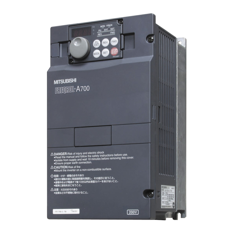
1 PRODUCT CHECKING AND PARTS IDENTIFICATION Unpack the inverter and check the capacity plate on the front cover and the rating plate on the inverter side face to ensure that the product agrees with your order and the inverter is intact. Inverter model - NA E740... - Page 5 PRODUCT CHECKING AND PARTS IDENTIFICATION General Precaution The bus capacitor discharge time is 10 minutes. Before starting wiring or inspection, switch power OFF, wait for more than 10 minutes, and check for residual voltage between terminal P/+ and N/- with a meter etc., to avoid a hazard of electrical shock. Environment Before installation, check that the environment meets following specifications.
-
Page 6: Outline Dimension Drawings
2 OUTLINE DIMENSION DRAWINGS When used with the plug-in option * When the FR-A7NC E kit is mounted, a terminal block protrudes making the depth approx. 2mm (0.08 inches) greater. (Unit:mm(inches)) Standard control circuit terminal model • Three-phase 200V class Inverter Type FR-E720-008 80.5(3.17) - Page 7 OUTLINE DIMENSION DRAWINGS (2) Safety stop function model • Three-phase 200V class Inverter Type FR-E720-008SC 86.5(3.41) 108.1(4.26) FR-E720-015SC 68(2.68) 56(2.20) 118.5(4.67) 140.1(5.52) FR-E720-030SC FR-E720-050SC 128(5.04) 118(4.65) 138.5(5.45) 160.1(6.3) FR-E720-080SC 108(4.25) 96(3.78) 141.5(5.57) 163.1(6.42) FR-E720-110SC 170(6.69) 158(6.22) 148.5(5.85) 170.1(6.7) FR-E720-175SC FR-E720-240SC 180(7.09) 164(6.46) 171(6.73)
-
Page 8: Wiring
Terminal connection diagram 3 WIRING Terminal connection diagram Standard control circuit terminal model 1. DC reactor (FR-HEL) *6 Terminal P1 is not available for single-phase Sink logic 100V power input model. When connecting a DC reactor, remove the Main circuit terminal jumper across P1-P/+ Control circuit terminal *7 A brake transistor is not built-in to the... - Page 9 Terminal connection diagram (2) Safety stop function model Sink logic 1. DC reactor (FR-HEL) Main circuit terminal When connecting a DC reactor, remove the Control circuit terminal jumper across P1-P/+ *6 A brake transistor is not built-in to the FR-E720-008SC and 015SC. Brake unit (Option) *7 Brake resistor (FR-ABR, MRS, MYS type)
- Page 10 Main circuit terminal specifications Main circuit terminal specifications 3.2.1 Terminal arrangement of the main circuit terminal, power supply and the motor wiring Three-phase 200V class FR-E720-008(SC) to 050(SC) FR-E720-080(SC) to 175(SC) Jumper Jumper Screw size (M3.5) N/- P/+ Screw size (M4) R/L1 S/L2 T/L3 R/L1 S/L2 T/L3 Screw size...
- Page 11 Main circuit terminal specifications Single-phase 200V class FR-E720S-008 to 030 FR-E720S-050 to 110 Jumper Jumper Screw size (M3.5) N/- P/+ Screw size (M4) R/L1 S/L2 R/L1 S/L2 Screw size Screw size (M4) (M3.5) Motor Power supply Power supply Motor Single-phase 100V class FR-E710W-008 to 030 FR-E710W-050 Jumper...
- Page 12 Main circuit terminal specifications 3.2.2 Cables and wiring length Cable sizes etc., of the main control circuit terminals and earth (ground) terminals Select the recommended cable size to ensure that a voltage drop will be 2% max. If the wiring distance is long between the inverter and motor, a main circuit cable voltage drop will cause the motor torque to decrease especially at the output of a low frequency.
- Page 13 Main circuit terminal specifications ∗1 The cable size is that of the cable (HIV cable (600V class 2 vinyl-insulated cable) etc.) with continuous maximum permissible temperature of 75°C (167°F). Assumes that the surrounding air temperature is 50°C (122°F) or less and the wiring distance is 20m (65.61feet) or less. ∗2 The recommended cable size is that of the cable (THHW cable) with continuous maximum permissible temperature of 75°C (167°F).
- Page 14 Main circuit terminal specifications Total wiring length The overall wiring length for connection of a single motor or multiple motors should be within the value in the table below. 100V, 200V class Pr. 72 PWM frequency selection Setting or More (carrier frequency) 200m 200m...
- Page 15 Control circuit specifications Control circuit specifications (1) Standard control circuit terminal model Control circuit terminal layout Terminal screw size M3: (Terminal A, B, C) M2: (Other than the above) 4 RUN FU SE STF STR Wiring method 1) Strip off the sheath of the wire of the control circuit to wire. Strip off the sheath about the size below.
- Page 16 Control circuit specifications Safety stop function model Control circuit terminal layout Recommend wire size: 0.3mm to 0.75mm S1 S2 Wiring method Use a blade terminal and a wire with a sheath stripped off for the control circuit wiring. For a single wire, strip off the sheath of the wire and apply directly.
- Page 17 Control circuit specifications 3) Insert the wire into a socket. When using a single wire or stranded wire without a blade terminal, push an open/close button all the way down with a flathead screw driver, and insert the wire. Open/close button Flathead screwdriver NOTE When using a stranded wire without a blade terminal, twist enough to avoid short circuit with a nearby terminals or...
-
Page 18: Precautions For Use Of The Inverter
PRECAUTIONS FOR USE OF THE INVERTER 4 PRECAUTIONS FOR USE OF THE INVERTER The FR-E700 series is a highly reliable product, but incorrect peripheral circuit making or operation/handling method may shorten the product life or damage the product. Before starting operation, always recheck the following items. (1) Use crimping terminals with insulation sleeve to wire the power supply and motor. - Page 19 PRECAUTIONS FOR USE OF THE INVERTER (12) Do not apply a voltage higher than the permissible voltage to the inverter I/O signal circuits. Application of a voltage higher than the permissible voltage to the inverter I/O signal circuits or opposite polarity may damage the I/O devices.
-
Page 20: Failsafe Of The System Which Uses The Inverter
FAILSAFE OF THE SYSTEM WHICH USES THE INVERTER FAILSAFE OF THE SYSTEM WHICH USES THE INVERTER When a fault occurs, the inverter trips to output a fault signal. However, a fault output signal may not be output at an inverter fault occurrence when the detection circuit or output circuit fails, etc. -
Page 21: Parameter List
PARAMETER LIST 6 PARAMETER LIST For simple variable-speed operation of the inverter, the initial setting of the parameters may be used. Set the necessary parameters to meet the load and operational specifications. Parameter setting, change and check can be made from the operation panel. - Page 22 PARAMETER LIST Initial Initial Name Setting Range Name Setting Range Value Value Terminal 4 frequency setting Reference value at 0 to 400Hz 60Hz 0 to 200%, 9999 9999 gain frequency acceleration PID control automatic 0 to 400Hz, 9999 9999 Reference value at switchover frequency 0 to 200%, 9999 9999...
- Page 23 PARAMETER LIST Initial Initial Name Setting Range Name Setting Range Value Value RL terminal function selection Output phase loss protection 0, 1 selection RM terminal function selection 0 to 5, 7, 8, 10, Life alarm status display (0 to 15) RH terminal function selection 12, 14 to 16, 18, Inrush current limit circuit life...
- Page 24 PARAMETER LIST Initial Initial Name Setting Range Name Setting Range Value Value Terminal 4 frequency setting Maintenance timer 0 (1 to 9998) 0 to 400Hz (904) bias frequency ∗5 Maintenance timer alarm Terminal 4 frequency setting 0 to 9998, 9999 9999 0 to 300% output set time...
-
Page 25: Troubleshooting
Reset method of protective function 7 TROUBLESHOOTING When a fault occurs in the inverter, the inverter trips and the PU display automatically changes to any of the following fault or alarm indications. If the fault does not correspond to any of the following faults or if you have any other problem, please contact your sales representative. - Page 26 List of fault or alarm indications List of fault or alarm indications Operation Panel Operation Panel Name Name Indication Indication E.ILF ∗1 Input phase loss E--- Faults history E.OLT Stall prevention stop HOLD Operation panel lock E. BE Brake transistor alarm detection LOCD Password locked Output side earth (ground) fault...
- Page 27 CE marking. The authorized representative in the EU The authorized representative in the EU is shown below. Name: Mitsubishi Electric Europe B.V. Address: Gothaer Strasse 8, 40880 Ratingen, Germany Note We declare that this inverter, when equipped with the dedicated EMC filter, conforms with the EMC Directive in industrial environments and affix the CE marking on the inverter.
- Page 28 Low Voltage Directive We have self-confirmed our inverters as products compliant to the Low Voltage Directive (Conforming standard EN 61800- 5-1) and affix the CE marking on the inverters. Outline of instructions ∗ Do not use an earth leakage circuit breaker as an electric shock protector without connecting the equipment to the earth. Connect the equipment to the earth securely.
- Page 29 ∗ Select a UL and cUL certified fuse with Class T fuse equivalent cut-off speed or faster with the appropriate rating for branch circuit protection, or a UL489 molded case circuit breaker (MCCB) in accordance with the table below. FR-E720- (SC)-NA Rated fuse voltage(V) 240V or more...
- Page 30 ∗ When using the electronic thermal relay function as motor overload protection, set the rated motor current to Pr. 9 Electronic thermal O/L relay. Electronic thermal relay function operation characteristic This function detects the overload (overheat) Pr. 9 = 100% setting of inverter rating*2 of the motor, stops the operation of the Pr.
- Page 31 Appendix 2 Instructions for UL and cUL (Standard to comply with: UL 508C, CSA C22.2 No. 14) 1. General Precaution The bus capacitor discharge time is 10 minutes. Before starting wiring or inspection, switch power off, wait for more than 10 minutes, and check for residual voltage between terminal P/+ and N/- with a meter etc., to avoid a hazard of electrical shock.
- Page 32 REVISIONS *The manual number is given on the bottom left of the back cover. Print Date Revision Manual Number Sep. 2007 IB-0600333ENG-A First edition Nov. 2007 IB-0600333ENG-B Addition • FR-E740-230, 300-NA Oct. 2008 IB-0600333ENG-C Addition • FR-E720S-008 to 110-NA • FR-E710W-008 to 050-NA Oct.
- Page 33 Additional notes for Instructions for UL and cUL Motor overload protection When using the electronic thermal relay function as motor overload protection, set the rated motor current in Pr.9 Electronic thermal O/L relay CAUTION Motor over temperature sensing is not provided by the drive. General precaution CAUTION - Risk of Electric Shock - The bus capacitor discharge time is 10 minutes.
- Page 34 FR-E700 Series Instruction Manual Supplement For the FR-E700 series manufactured in December 2014 or later, the following specifications are added. Check the serial number printed on the rating plate of the inverter. Voltage reduction selection during stall prevention operation (Pr.154) Parameter Initial Setting...
- Page 35 Operation FR-PU04 panel E.OV2 Stedy Spd OV FR-PU07 indication Name Regenerative overvoltage trip during constant speed If regenerative energy causes the inverter's internal main circuit DC voltage to reach or exceed the specified value, the protective circuit is activated to stop Description the inverter output.
- Page 36 SERIAL number check Check the serial number printed on the rating plate of the inverter. Refer to the inverter manual for the location of the rating plate. Rating plate example Symbol Year Month Control number SERIAL (Serial No.) The SERIAL consists of one symbol, two characters indicating production year and month, and six characters indicating control number.
- Page 37 MEMO BCN-C22005-679...
- Page 38 Year, and the Month is indicated by 1 to 9, X (October), Y (November), or Z (December). •Authorized sales representative (importer) in the CU area The authorized sales representative (importer) in the CU area is shown below. Name: Mitsubishi Electric (Russia) LLC Address: 52, bld 1 Kosmodamianskaya Nab 115054, Moscow, Russia Phone: +7 (495) 721-2070...
- Page 39 • The copyright and other rights of this CD-ROM all belong to Mitsubishi Electric Corporation. • No part of this CD-ROM may be copied or reproduced without the permission of Mitsubishi Electric Corporation. • Specifications of this CD-ROM are subject to change for modification without notice.
- Page 40 電器電子製品有害物質使用制限について 中華人民共和国の『電器電子製品有害物質使用制限管理弁法』に基づき、 「電器電子製 品有害物質使用制限の標識」の内容を以下に記載いたします。 Restricted Use of Hazardous Substances in Electronic and Electrical Products The mark of restricted use of hazardous substances in electronic and electrical products is applied to the product as follows based on the “Management Methods for the Restriction of the Use of Hazardous Substances in Electrical and Electronic Products”...
- Page 41 FR-E700 Series Instruction Manual Supplement Instructions for UL and cUL have been revised. Instructions for UL and cUL (Standard to comply with: UL 508C, CSA C22.2 No. 14) 2. Installation The below types of inverter have been approved as products for use in enclosure and approval tests were conducted under the following conditions.
- Page 42 Model Manufacturer Rated Voltage, Vac MMP-T32 Mitsubishi Electric Corp. 480Y/277 Suitable for Use in a Circuit Capable of Delivering Not More Than 50 or 25 kA rms Symmetrical Amperes, 480Y/277 Volts Maximum when protected by the Type E Combination motor Controllers indicated in the above table.
- Page 43 HEADQUARTERS EUROPEAN REPRESENTATIVES EUROPEAN REPRESENTATIVES EUROPEAN REPRESENTATIVES MITSUBISHI ELECTRIC EUROPE GEVA AUSTRIA MITSUBISHI ELECTRIC IRELAND Beijer Electronics AB SWEDEN EUROPE B.V. Wiener Straße 89 EUROPE B.V.-Irish Branch Box 426 German Branch A-2500 Baden Westgate Business Park S-20123 Malmö Gothaer Straße 8...