Siemens SIPROCESS GA700 Quick Start Manual
Continuous gas analysis
Hide thumbs
Also See for SIPROCESS GA700:
- Operating manual (306 pages) ,
- Compact operating instructions (244 pages) ,
- Operating instructions manual (224 pages)
Table of Contents
Advertisement
Quick Links
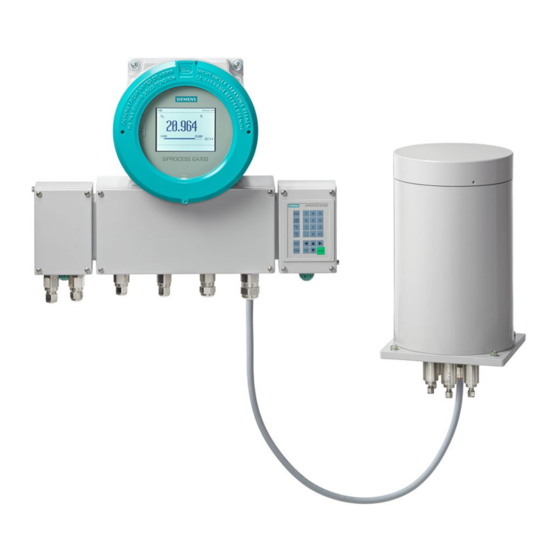
Continuous gas analysis
SIPROCESS GA700
Quick Start
Compact Operating Instructions
05/2018
A5E31805656-06
___________________
Introduction
___________________
Safety instructions
___________________
General information
___________________
Combination operation
___________________
Installing
___________________
Connecting
___________________
Commissioning
___________________
Operation
___________________
Service and maintenance
___________________
Dismantling and disposal
___________________
Technical specifications
___________________
Appendix A
1
2
3
4
5
6
7
8
9
10
11
A
Advertisement
Table of Contents

Related Manuals for Siemens SIPROCESS GA700


Summary of Contents for Siemens SIPROCESS GA700
- Page 1 ___________________ Introduction ___________________ Safety instructions ___________________ Continuous gas analysis General information ___________________ Combination operation SIPROCESS GA700 Quick Start ___________________ Installing ___________________ Connecting Compact Operating Instructions ___________________ Commissioning ___________________ Operation ___________________ Service and maintenance ___________________ Dismantling and disposal ___________________ Technical specifications...
- Page 2 Note the following: WARNING Siemens products may only be used for the applications described in the catalog and in the relevant technical documentation. If products and components from other manufacturers are used, these must be recommended or approved by Siemens. Proper transport, storage, installation, assembly, commissioning, operation and maintenance are required to ensure that the products operate safely and without any problems.
-
Page 3: Table Of Contents
Table of contents Introduction ............................. 7 Purpose of this document ......................7 History ............................7 Purpose ............................. 8 Field of application ........................8 Qualified personnel ........................9 Checking delivery ........................9 Transportation and storage ..................... 10 Warranty conditions ........................ 10 Safety instructions .......................... - Page 4 Table of contents Installing ............................... 31 General safety instructions for installation ................31 Installation instructions ......................33 Rack-mounted device ......................34 5.3.1 Device-specific safety instructions ..................34 5.3.2 Installing the rack-mounted device ..................35 Wall-mounted device ......................36 5.4.1 Device-specific safety instructions ..................36 5.4.2 Installing the wall-mounted device ..................
- Page 5 Table of contents Introduction of reference gas ....................77 7.4.1 General information on reference gas ..................77 7.4.2 Introducing reference gas ....................... 78 7.4.3 Requirements for reference gas from the gas cylinder ............78 7.4.4 Check the reference gas flow ....................78 7.4.5 Reference gas monitoring with pressure switch ..............
- Page 6 Table of contents Technical specifications ........................119 11.1 Determining the technical specifications ................119 11.2 Technical specifications of rack-mounted housing .............. 119 11.3 Technical specifications of the wall housing ................ 121 11.4 Technical specifications of analyzer modules ..............123 11.4.1 OXYMAT 7 technical specifications ..................
-
Page 7: Introduction
Introduction Purpose of this document These compact operating instructions are a brief summary of important features, functions and safety instructions, and contain all the information required for safe use of the device. This is information on the mounting, connection, commissioning, operation, maintenance and servicing of the device. -
Page 8: Purpose
"Devices in explosion-proof version", see Table A-5 References 5 - Compact Operating Instructions Ex (Page 136). A SIPROCESS GA700 device comprises of a basic device (enclosure) into which up to two exchangeable analyzer modules can be inserted. The basic device can be delivered in two variants: As a 19'' rack-mounted enclosure with three height units or as an enclosure for wall mounting. -
Page 9: Qualified Personnel
Introduction 1.5 Qualified personnel The following table provides an overview of the device versions. Table 1- 2 SIPROCESS GA700 devices with analyzer modules Device variants MLFB number Basic devices: Rack-mounted device 7MB3000-0****-**** Wall-mounted device 7MB3000-3****-**** 7MB3000-4****-**** Analyzer modules, standard version:... -
Page 10: Transportation And Storage
All obligations on the part of Siemens AG are contained in the respective sales contract, which also contains the complete and solely applicable liability provisions. The provisions defined in the sales contract for the responsibility for defects are neither extended nor limited by the remarks in this document. -
Page 11: Safety Instructions
Safety instructions Requirement for safe use In terms of safety, this device left the factory in perfect condition. In order to maintain this status and to ensure safe operation of the device, observe these compact operating instructions and all the information relevant to safety. Observe the information and symbols on the device. -
Page 12: Conformity With European Directives
Safety instructions 2.2 Basic safety instructions 2.1.3 Conformity with European directives The CE marking on the device shows conformity with the regulations of the following European guidelines: Electromagnetic compatibility Directive of the European Parliament and of the Council EMC 2014/30/EU of 26 February 2014 on the harmonization of the laws of the Member States relating to electromagnetic compatibility (new version) - Page 13 Safety instructions 2.2 Basic safety instructions WARNING Device modifications Danger to personnel, system and the environment can result from modifications and repairs to the device. • Only carry out modifications or repairs that are described in the operating instructions for the device.
- Page 14 Safety instructions 2.2 Basic safety instructions Quick Start Compact Operating Instructions, 05/2018, A5E31805656-06...
-
Page 15: General Information
10 seconds for older devices to switch over, and up to 100 seconds to switch to safe operating mode. If you are using SIPROCESS GA700 devices in critical processes, observe the following information: ● Monitor the limits externally via the control system. -
Page 16: Measuring High Oxygen Concentrations
General information 3.3 Measuring high oxygen concentrations Measuring high oxygen concentrations Note Measuring high oxygen concentrations For the measurement of high O concentrations in excess of 25%, it is absolutely necessary that all parts that come in contact with the sample gas are free of oil and grease and do not contain any particles that could react with O We highly recommend you use specially cleaned analyzer modules with the "Cleaned for O "... -
Page 17: Combination Operation
Combination operation Slots for analyzer modules The figure below shows the slots for the analyzer modules. Rack-mounted device - rear view: ① Slot 1 (AM1), example OXYMAT 7 ② Slot 2 (AM2), example CALOMAT 7 Wall-mounted device - rear view: ③... -
Page 18: Operating Modes
Combination operation 4.2 Operating modes Operating modes 4.2.1 Setting note Note Operating mode-specific parameter assignment of the gas path in serial/parallel operation Analyzer modules can be operated in series or in parallel. • If you are only using one analyzer module or want to operate two analyzer modules in series, set the value "Shared"... -
Page 19: Changing The Operating Mode
Combination operation 4.3 Gas connections 4.2.4 Changing the operating mode Please observe the following points when switching between the operating modes: ● Check the mounting positions of sample gas restrictors or clamping screws at the sample gas connections. If required, change them in accordance with the selected operating mode. - Page 20 Combination operation 4.3 Gas connections Overview ① Version with pipes: Sample gas bushing with 6 mm connection fittings. ② Sample gas restrictors ③ Version with hoses: Sample gas bushing with 6 mm connection fittings Figure 4-2 Sample gas connections with sample gas restrictors For rack-mounted and wall-mounted devices, the sample gas connections of the analyzer modules are 6 mm nozzles.
- Page 21 Combination operation 4.3 Gas connections Distinction between sample gas restrictors and clamping screws The sample gas restrictor and clamping screw differ in the bolt head and at the outlet diameter at the bottom end. ● Sample gas restrictor: Slotted screw; outlet diameter 0.5 mm. ●...
-
Page 22: Mounting Conditions
Combination operation 4.3 Gas connections 4.3.2 Mounting conditions Overview of mounting position ① Gas connection before installation of sample gas restrictor or clamping screw ② Gas connection after installation of sample gas restrictor or clamping screw ③ Rear clamp ring ④... - Page 23 Combination operation 4.3 Gas connections OXYMAT 7 Note Additional clamping screws Additionally required clamping screws are not included in the scope of delivery. Order the clamping screws separately. Table 4- 1 Mounting position of the sample gas restrictor: OXYMAT 7 Operating Sample gas restrictor/clamping screw mode...
- Page 24 Combination operation 4.3 Gas connections CALOMAT 7 Table 4- 3 Mounting position for the sample gas restrictor: CALOMAT 7 Operating mode Clamping screw Operation with one or two CALOMAT 7 Pressure operation/Suction operation Pre-assembled clamping screws. No retrofitting or disman- tling.
- Page 25 Combination operation 4.3 Gas connections Retrofitting example: "Pressure operation, serial" for OXYMAT 7/ULTRAMAT 7 When you are replacing the ULTRAMAT 7 with an OXYMAT 7 analyzer module, you must replace the sample gas restrictor in the sample gas inlet with a clamping screw. MGE, VGE Sample gas inlet (MGE), Reference gas inlet (VGE) ①...
-
Page 26: Plug & Measure: Permissible Activities
Combination operation 4.4 Plug & Measure: Permissible activities Plug & Measure: Permissible activities 4.4.1 General information Term "Plug & Measure" is the ability to recognize any analyzer modules and/or option modules added at a later time and to integrate them. This ability makes it easier to replace modules for maintenance purposes as well as installing devices at a later time, for example, option modules. - Page 27 Combination operation 4.4 Plug & Measure: Permissible activities NOTICE Deletion of the analyzer module parameter assignment due to faulty operation during commissioning During commissioning after replacement of the AM electronics, a faulty operation can prevent transfer of the parameters and render the AM electronics unusable. When you commission the device once again after replacing the AM electronics, the following applies: •...
-
Page 28: Case Differentiations
Combination operation 4.4 Plug & Measure: Permissible activities 4.4.3 Case differentiations Table 4- 5 Plug & Measure - Commissioning Case Description Data synchronization/Action Commissioning, PM without serial Automatic data synchronization number Commissioning, each module has a Automatic data synchronization serial number stored at the factory. None of the modules has been con- nected to another module before Data synchronization: PM parameters are transferred to the AMx (x=1 or 2), parameters of the... - Page 29 Combination operation 4.4 Plug & Measure: Permissible activities Table 4- 7 Plug & Measure installation of a PM into an existing (configured) device / replacement of a PM in an existing (configured) device Case Description Data synchronization/Action Unchan The PM electronics is replaced. "-" is Automatic data synchronization , no displayed instead of the serial num-...
- Page 30 Combination operation 4.4 Plug & Measure: Permissible activities Table 4- 9 Plug & Measure - AM slot change Case Description Data synchronization/Action Unchan- AM1 → Internal swapping of modules be- None tween slots is not permitted! AM2 → Install the modules once again in their previous slot and restart the device.
-
Page 31: Installing
Note Material compatibility Siemens can provide you with support concerning selection of analyzer components wetted by the process medium. However, the device operator is responsible for the selection of components. Siemens accepts no liability for faults or failures resulting from incompatible materials. - Page 32 Installing 5.1 General safety instructions for installation WARNING Insufficient ventilation Risk of fire The device may overheat or start burning in the case of insufficient ventilation. • Make sure that the room is sufficiently ventilated. Refer to the information in section "Technical specifications (Page 119)". NOTICE Improper installation The device can be damaged or destroyed or its functionality impaired through an incorrect...
-
Page 33: Installation Instructions
Installing 5.2 Installation instructions Installation instructions Note Layout of the installation location The installation location should be: • Easily accessible • Shock-free and vibration-free • Within the ambient temperature limits Note Weatherproof installation Install the device at a location where it is protected against: •... -
Page 34: Rack-Mounted Device
Installing 5.3 Rack-mounted device Rack-mounted device 5.3.1 Device-specific safety instructions NOTICE Insufficient air circulation around the device Device damage The device may overheat in case of heat accumulation. • Make sure that sufficient air circulates around the rack-mounted device. • Do not cover the ventilation slit. •... -
Page 35: Installing The Rack-Mounted Device
Installing 5.3 Rack-mounted device 5.3.2 Installing the rack-mounted device Dimension drawing The following figure shows the dimensions of the rack-mounted device and the distance of the fastening holes at the mounting brackets. The dimensions are specified in millimeters. Figure 5-1 Dimension drawing Procedure 1. -
Page 36: Wall-Mounted Device
Installing 5.4 Wall-mounted device Wall-mounted device 5.4.1 Device-specific safety instructions 5.4.2 Installing the wall-mounted device Dimension drawing The following figure shows the dimensions of the wall-mounted device and the distance of the fastening holes. The dimensions are specified in millimeters. Figure 5-2 Drilling template and side view Quick Start... - Page 37 Installing 5.4 Wall-mounted device Figure 5-3 Dimensions with open wall-mounted device Procedure 1. Drill four holes into the wall. The dimensions for the drill holes are specified in the drilling pattern. 2. Insert the anchors in the drilled holes. 3. Position the wall-mounted device on the wall and fasten it with the screws. Quick Start Compact Operating Instructions, 05/2018, A5E31805656-06...
- Page 38 Installing 5.4 Wall-mounted device Quick Start Compact Operating Instructions, 05/2018, A5E31805656-06...
-
Page 39: Connecting
Connecting Gas connections 6.1.1 General safety instructions for gas connections WARNING Introduction of toxic, corrosive or flammable gases The limited release of toxic or corrosive gases during their introduction cannot be avoided with absolute certainty. • Before toxic, corrosive or flammable gases are introduced, carry out a leak test for the pipe connections. -
Page 40: Connection Information
Connecting 6.1 Gas connections 6.1.2 Connection information Note Identifier of the gas connections The identifiers of the gas connections are imprinted as numbers 1 to 4 on the module plate. Note Pipes Connect the pipes with the gas connections using suitable clamping screws. Use only such connecting parts (pipes, threaded joints, etc.) coming into contact with sample gas that are resistant to the sample gas. - Page 41 Connecting 6.1 Gas connections Note Shutting off the sample gas inlet and outlet If you shut off the sample gas inlet and outlet, make sure that the reference gas can escape, for example, by a 2-way valve at the sample gas outlet. Alternatively, the connection of an overpressure valve is possible.
-
Page 42: Installing/Removing The Sample Gas Restrictor
Connecting 6.1 Gas connections 6.1.3 Installing/removing the sample gas restrictor Requirements Before you install/remove the sample gas restrictor, ensure that ● the sample gas line is disconnected from the device, ● you have read the section "Combination operation (Page 17)", ●... -
Page 43: Gas Connections For Rack Device/Wall-Mounted Device
Connecting 6.1 Gas connections 6.1.4 Gas connections for rack device/wall-mounted device 6.1.4.1 OXYMAT 7 Arrangement of the gas connections in the rack-mounted device ① Slot of analyzer module 1: OXYMAT 7 ② Slot of analyzer module 2 Sample gas inlet Sample gas outlet Not assigned, bypass outlet for version with external reference gas pump Reference gas inlet... - Page 44 Connecting 6.1 Gas connections Arrangement of the gas connections in the wall-mounted device ① Purging gas inlet ② Purging gas outlet ③ Slot of analyzer module 2 ④ Slot of analyzer module 1: OXYMAT 7 Sample gas inlet Sample gas outlet Not assigned, bypass outlet for version with external reference gas pump Reference gas inlet Figure 6-2...
- Page 45 Connecting 6.1 Gas connections High-temperature OXYMAT 7: Arrangement of the gas connections in the wall-mounted device ① Purging gas inlet ② Purging gas outlet ③ Reference gas inlet ④ Sample gas outlet ⑤ Sample gas inlet Figure 6-3 Gas connections of a high-temperature OXYMAT 7 in the wall-mounted unit, bottom Design of the gas connections Gas connection Material...
-
Page 46: Ultramat 7
Connecting 6.1 Gas connections 6.1.4.2 ULTRAMAT 7 Arrangement of the gas connections in the rack-mounted device ① Slot of analyzer module 1: ULTRAMAT 7 ② Slot of analyzer module 2 Sample gas inlet Sample gas outlet Reference gas outlet Reference gas inlet Atmospheric pressure sensor Figure 6-4 ULTRAMAT 7 gas connections in the rack-mounted device, rear... - Page 47 Connecting 6.1 Gas connections Arrangement of the gas connections in the wall-mounted device ① Purging gas inlet ② Purging gas outlet ③ Slot of analyzer module 2 ④ Slot of analyzer module 1: ULTRAMAT 7 Sample gas inlet Sample gas outlet Reference gas outlet Reference gas inlet Atmospheric pressure sensor...
-
Page 48: Calomat 7
Connecting 6.1 Gas connections 6.1.4.3 CALOMAT 7 Arrangement of the gas connections in the rack-mounted device ① Slot of analyzer module 1: CALOMAT 7 ② Slot of analyzer module 2 Sample gas inlet Sample gas outlet Not assigned Not assigned Figure 6-6 CALOMAT 7 gas connections in the rack unit, rear Quick Start... - Page 49 Connecting 6.1 Gas connections Arrangement of the gas connections in the wall-mounted device ① Purging gas inlet ② Purging gas outlet ③ Slot of analyzer module 2 ④ Slot of analyzer module 1: CALOMAT 7 Sample gas inlet Sample gas outlet Not assigned Not assigned Figure 6-7...
-
Page 50: Purging Gas Connections On Wall-Mounted Device
Connecting 6.1 Gas connections 6.1.4.4 Purging gas connections on wall-mounted device Overview When measuring toxic or corrosive gases, the gas path may start to leak and sample gas can accumulate in the device. This means that devices, in particular those that are used in hazardous areas, must be purged with purging gas (oil-free dry air or inert gas). -
Page 51: Connecting Gas
Connecting 6.2 Electrical connections Design of the gas connections Dimensions of purging gas couplings Diameter Exterior 12 mm Length Without sealing caps 28 mm With sealing caps 41 mm 6.1.5 Connecting gas Procedure 1. Connect the gas lines by means of suitable clamping screws to the associated gas inlets and outlets. -
Page 52: Connection Information
Connecting 6.2 Electrical connections WARNING Missing PE/ground terminal Danger of electrocution If there is no ground terminal, there is a risk of electrocution. Depending on the device version, connect the power supply as follows: • Power plug: Ensure that the used socket has a PE/ground terminal. Check that the PE/ground terminal of the socket and power plug match. -
Page 53: Requirements For Electrical Connection
Connecting 6.2 Electrical connections Note Improvement of interference immunity • Lay signal cables separately from cables with voltages > 60 V. • Use cables with twisted wires. • Install the device and lay its cables at a distance to strong electromagnetic fields. •... - Page 54 Connecting 6.2 Electrical connections Overview Detail view of option module connections ① OM1.1 and OM2.1/2.2 with embossed connector numbers on the enclosure's rear panel ② Power supply ③ Processing module, Ethernet (MODBUS TCP), and 37-pin sub-D (female), digital inputs and outputs ④...
-
Page 55: Connecting The Power Supply
Connecting 6.2 Electrical connections 6.2.4.2 Connecting the power supply Note Appliance plug You can use any appliance plug that fulfills the conditions of DIN EN 60320-1, ≥ 6 A to connect the device. Overview ① ③ Power supply unit Appliance plug ②... -
Page 56: Electrical Connections And Pin Assignments At The Rack-Mounted Device
Connecting 6.2 Electrical connections 6.2.4.3 Electrical connections and pin assignments at the rack-mounted device Note Number of inputs and outputs The number of inputs/outputs that are actually available in the device depends on the installed optional modules. The paragraph below includes an overview of all inputs/outputs. Figure 6-11 Pin assignments of processing module Quick Start... - Page 57 Connecting 6.2 Electrical connections Figure 6-12 Pin assignment of optional module 1.1 Quick Start Compact Operating Instructions, 05/2018, A5E31805656-06...
- Page 58 Connecting 6.2 Electrical connections Figure 6-13 Pin assignment of optional module 2.1 Note Limited number of analog outputs Because of the functional principle, only a limited number of analog outputs is available. Quick Start Compact Operating Instructions, 05/2018, A5E31805656-06...
- Page 59 Connecting 6.2 Electrical connections Figure 6-14 Pin assignment of optional module 2.2 Quick Start Compact Operating Instructions, 05/2018, A5E31805656-06...
-
Page 60: Connecting Wall-Mounted Device Electrically
Connecting 6.2 Electrical connections 6.2.5 Connecting wall-mounted device electrically 6.2.5.1 Device-specific safety instructions WARNING Danger due to electrical current The power cable to be connected at the customer location could be damaged by improper connection to the device. • Check whether the existing line voltage corresponds to the line voltage specified on the nameplate of the device or in the technical specifications. -
Page 61: Connecting The Signal Cables
Connecting 6.2 Electrical connections 6.2.5.2 Connecting the signal cables Overview ① Screws for door ② Shielding plate ③ Cable glands for signal lines (7 pieces) ④ Power supply cable gland Figure 6-15 Wall-mounted device, connecting signal cables Procedure ① 1. Undo the six screws and open the door of the wall-mounted device. -
Page 62: Connecting The Ethernet Cable
Connecting 6.2 Electrical connections ③ 5. Insert the signal cable through this cable gland 6. Insert the stripped conductors of the signal cable into the terminal block in accordance with the terminal assignment. ③ 7. Fasten the signal cable in the cable gland . - Page 63 Connecting 6.2 Electrical connections 2. Fasten the prepared gland at the device: ⑥ Plate with cable glands ⑦ Position cable gland Ethernet cable (underside of the device) Figure 6-17 Ethernet cable: Position of the cable gland ⑦ ⑥ – Fasten the Ethernet cable in the cable gland at the plate Connecting the Ethernet cable 1.
-
Page 64: Connecting The Power Supply
Connecting 6.2 Electrical connections 6.2.5.4 Connecting the power supply Overview ① ④ Power supply unit Shielding plate ② ⑤ Appliance plug Power supply cable gland ③ ⑥ Screws for door Equipotential bonding Figure 6-18 Wall-mounted device, connecting power supply Quick Start Compact Operating Instructions, 05/2018, A5E31805656-06... -
Page 65: Electrical Connections And Terminal Assignment At The Wall-Mounted Device
Connecting 6.2 Electrical connections Procedure ③ 1. Undo the six screws and open the door of the wall-mounted device. ④ 2. Remove the shielding plate on the right side panel. To do this loosen the screws. ⑤ 3. Unscrew the union nut of the cable gland ⑤... - Page 66 Connecting 6.2 Electrical connections Figure 6-19 Pin assignment of standard terminal block, terminal rows A and B Quick Start Compact Operating Instructions, 05/2018, A5E31805656-06...
- Page 67 Connecting 6.2 Electrical connections Figure 6-20 Pin assignment of standard terminal block, terminal rows C and D Note Limited number of analog outputs Because of the functional principle, only a limited number of analog outputs is available. Quick Start Compact Operating Instructions, 05/2018, A5E31805656-06...
- Page 68 Connecting 6.2 Electrical connections Figure 6-21 Options for the assignment of the terminal block, terminal rows A and B Quick Start Compact Operating Instructions, 05/2018, A5E31805656-06...
-
Page 69: Spark Suppression: Example
Connecting 6.2 Electrical connections Figure 6-22 Options for the assignment of the terminal block, terminal rows C and D 6.2.6 Spark suppression: Example NOTICE Damage to the digital outputs due to missing external protective circuit Arcs can result when switching inductances without external protective circuit; these can damage the digital outputs/relays. -
Page 70: Overview: Spark Suppression For Rack-Mounted Device
Connecting 6.2 Electrical connections 6.2.6.1 Overview: Spark suppression for rack-mounted device ① Sub-D connector, 37-pin: Pin number 6: Function in the analyzer ② Terminal end/spark suppression ③ Power supply unit DI ... Digital input. Floating " 0 V (-3 ... +5 V) via optocoupler: "... -
Page 71: Overview: Spark Suppression For Wall-Mounted Device
Connecting 6.2 Electrical connections 6.2.6.2 Overview: Spark suppression for wall-mounted device ① Standard terminal block, terminal row A: Function in the analyzer ② Terminal end/spark suppression ③ Power supply unit Digital outputs: Contact load max. 24 V/1.7 A, AC/DC. Shown relay contacts: relay coil has zero current Figure 6-24 Wall-mounted device: Example of spark suppression on a relay contact... - Page 72 Connecting 6.2 Electrical connections Quick Start Compact Operating Instructions, 05/2018, A5E31805656-06...
-
Page 73: Commissioning
Commissioning General safety instructions for commissioning WARNING Commissioning and operation with error message If an error message is displayed, correct operation in the process is no longer guaranteed. • Check to see which error is pending. • Correct the error. •... -
Page 74: General Information On Commissioning
Commissioning 7.2 General information on commissioning CAUTION Hot surfaces resulting from hot sample gases and heated devices Danger of burns resulting from surface temperatures above 70 °C (155 °F). • Take appropriate protective measures, for example contact protection. • Make sure that the maximum ambient temperature is not exceeded by implementing protective measures. - Page 75 Commissioning 7.2 General information on commissioning Note Signal frequencies with two OXYMAT 7 analyzer modules If you install a second OXYMAT 7 analyzer module, the operating and signal frequencies of the two OXYMAT 7 analyzer modules have to differ from each other. •...
-
Page 76: Gas Preparation
Commissioning 7.3 Gas preparation Note Using an external pressure sensor An external pressure sensor can process ambient or sample gas pressure values up to 3 bar (abs.), regardless of the application. You can obtain additional information on the use of external pressure sensors from your service partner: →... -
Page 77: Introduction Of Reference Gas
Commissioning 7.4 Introduction of reference gas We recommend installing the following devices upstream of the sample gas inlet for gas preparation: ● Gas sampling device with filter ● Sample gas cooler ● Analyzer filter, medium pore size <10 µm ● Gas suction pump Depending on the composition of the sample gas, you may need additional equipment such as a wash bottle, additional filters and pressure reducers. -
Page 78: Introducing Reference Gas
Commissioning 7.4 Introduction of reference gas 7.4.2 Introducing reference gas ● Set the flow of sample gas and reference gas to the same level. ● Always introduce the reference gas before introducing the sample gas. Note Introduction of the reference gas during measurement interruptions In the case of temporary interruption of the measurements, keep introducing the reference gas into the analyzer module. -
Page 79: Reference Gas Monitoring With Pressure Switch
• Contact the Service (Page 137). • Have the pressure switching point of the reference gas pressure switch adjusted by a Siemens technician or someone trained for this scenario. Checking pressure switch for function 1. Increase the reference gas pressure until the pressure switch is triggered, meaning that the switch contact opens. -
Page 80: Recommended Test Setup
Commissioning 7.5 Checking gas paths for leaks Checking for leaks 1. Perform a leak test with air or nitrogen (test gas) at the operating temperature. 2. Determine the leak rate in accordance with the pressure drop method. To do this monitor the pressure of the gas (air or nitrogen) enclosed in the gas line for a defined period. -
Page 81: Checking The Oxymat 7 For Leaks
Commissioning 7.5 Checking gas paths for leaks Test setup for leakage test To check for leaks, we recommend the test setup shown below: ① Shut-off valve ② Pressure regulator ③ Manometer (gauge pressure) Sample gas inlet Sample gas outlet ULTRAMAT 7: Unscrewing blanking plugs OXYMAT 7 / ULTRAMAT 7: Unscrewing blanking plugs Figure 7-2 Recommended test setup to check for leaks... -
Page 82: Checking The Ultramat 7 For Leaks
Commissioning 7.5 Checking gas paths for leaks Procedure: Devices with hoses 1. Close the reference gas inlet and, for versions with an external reference gas pump, also the bypass outlet. 2. Connect a pressure measuring instrument (manometer) to the sample gas outlet. 3. -
Page 83: Checking The Calomat 7 For Leaks
Commissioning 7.6 Requirements for startup 7.5.5 Checking the CALOMAT 7 for leaks Procedure 1. Connect a pressure measuring instrument (manometer) to the sample gas outlet. Measuring range approx. 200 hPa rel. to 1000 hPa rel. with appropriate measured value resolution (0.1 hPa). Absolute pressure gauges with correspondingly good resolution are also suitable. -
Page 84: Commissioning The Device
Commissioning 7.7 Commissioning the device Commissioning the device Startup ① Product designation ② Version of the device firmware ③ Progress bar Figure 7-3 Splash screen 1. Supply device with power: Information on the device power supply is available in the section "Electrical connections (Page 51)"... - Page 85 Commissioning 7.7 Commissioning the device 3. Wait for transition to warming-up phase: When the splash screen disappears, the device is in the warming-up phase. A bar chart in the dialog window shows the current temperature progress. 4. Access the measured value display during the warm-up phase: –...
- Page 86 Commissioning 7.7 Commissioning the device 4. Disable automatic logoff temporarily: The factory setting is a logoff time of 5 min. When this time elapses, changes that were not stored retentively are lost. We recommend that you temporarily deactivate automatic logoff during commissioning. For additional information, refer to: →...
-
Page 87: [1.1] Input Of Basic Settings
Commissioning 7.7 Commissioning the device 7.7.1 [1.1] Input of basic settings Procedure 1. "1 Quick Start" > "01 Basic settings" main menu 2. Call the parameter display: Press <Enter>. 3. Set the display language. If the language of the Quick Start Manual was also set as operating language, this is set at the factory;... -
Page 88: [1.2] Set Automatic Log-Off
Commissioning 7.7 Commissioning the device 7.7.2 [1.2] Set automatic log-off Setting notes Note Function of automatic logoff When this function is activated and the logoff time expires, the device logs you off automatically. All changes that are not saved permanently will be discarded. The measured value display of all components is displayed again. -
Page 89: [1.3] Set Analog Outputs
Commissioning 7.7 Commissioning the device 7.7.3 [1.3] Set analog outputs Overview Note Availability of the menu This menu is only available if your device has at least one of the option modules (2.1 and/ or 2.2) installed. If the option modules are not installed in the device, the "Quick Start" menu has a corresponding menu entry. - Page 90 Commissioning 7.7 Commissioning the device Setting analog output ranges 1. Call up submenu "04 Analog outputs": Main menu > "1. Quick Start" > "04 Analog outputs" The menu includes one navigation line for each of the five analog output ranges that can be set: Structure of the navigation line for each analog output range Component name...
-
Page 91: [1.4] Measuring Ranges
Commissioning 7.7 Commissioning the device 7.7.4 [1.4] Measuring ranges 7.7.4.1 Overview of measuring ranges Note Putting back into operation with disabled measuring ranges The measuring ranges are activated in the factory. If you disable the measuring ranges (setting: "Off"), all the setting options in other menus related to the measuring range are also hidden. -
Page 92: Setting The Measuring Ranges
Commissioning 7.7 Commissioning the device Measuring range type 1 (mr i < mr (i+1)) The full-scale value of measuring range (i) must be lower than the full-scale value of the subsequent measuring range (i+1). The following switchover points are used: High switchover point (= full-scale value Low switchover point (= full-scale value minus 10 % of the span) - Page 93 Commissioning 7.7 Commissioning the device Procedure 1. Call up submenu "n component": Main menu > "1. Quick Start" > "4. Measuring ranges" > "n component" The menu includes a navigation line for setting of autoranging. One navigation line is reserved for each of the four measuring ranges that can be set: Structure of the navigation line for each measuring range Measuring range Measuring range start - measuring range end...
-
Page 94: Setting Autoranging
Commissioning 7.7 Commissioning the device 4. Enable/disable measuring range: "Use measuring range" parameter field. Note Using measuring ranges in other device functions/menus Other device functions or menus can only access measuring ranges activated in this menu. Inactive measuring ranges are not displayed for selection in other device functions/menus. - Page 95 Commissioning 7.7 Commissioning the device 7.7.5 [1.5] Calibration Note Component-specific setup Measuring ranges are component-specific. Repeat the procedure described below for all the components, if necessary. Procedure 1. Call up submenu "n component": Main menu > "1. Quick Start" > "4. Measuring ranges" > "n component" The menu includes a navigation line for setting of autoranging.
-
Page 96: Calibration
Commissioning 7.7 Commissioning the device Note Setpoints for zero/span gas beyond the min./max. limits After changing the start-of-scale value and/or the end-of-scale value, the setpoints for zero/span gas may be outside the configured limits. The "[150] - Parameter value invalid" message appears: •... - Page 97 – "Factory calibrations" (normalization and phase calibration). The section below only covers the area of "Customer calibrations". Information on factory calibrations is available under → [2.20.03] Factory calibrations. Contact you Siemens sales rep for more information. ● Single/total: Calibration of only one or all measuring ranges ●...
- Page 98 Commissioning 7.7 Commissioning the device Calibration Description 2-point calibration In this type of calibration, zero gas validation and span gas calibration take place successively. 1-point calibration with substitute gas Because the thermal conductivity sensor of the CALOMAT 7 shows a stable char- to shift the characteristic offset acteristics gradient after an operating time of about 3 months, regular 2-point cali- bration is no longer necessary.
-
Page 99: Carrying Out Calibration/Validation
Commissioning 7.7 Commissioning the device Sequence When you start the calibration, a wizard is started that guides you through calibration. Depending on the type of calibration selected, the wizard includes the following steps: Figure 7-4 Steps during calibration 7.7.5.2 Carrying out calibration/validation Procedure 1. - Page 100 Commissioning 7.7 Commissioning the device 4. Specify the scope of the calibration: "Single/total" parameter field. By setting this parameter you define the scope of the calibration - one or all measuring ranges. The measuring range set in the calibration is always calibrated: –...
-
Page 101: [1.6] Save Parameter Set
Parameter sets overview You can use this menu to save your latest settings in a parameter set. You can use it to restore any unintentional changes to the parameter assignment. SIPROCESS GA700 devices use two types of parameter sets: ● Factory data: This parameter set is the factory default and is used to restore the original parameter assignment. - Page 102 Commissioning 7.7 Commissioning the device Quick Start Compact Operating Instructions, 05/2018, A5E31805656-06...
-
Page 103: Operation
Operation Local User Interface (LUI) Operating elements The LUI (Local User Interface) of the SIPROCESS GA700 devices has the following operating elements: ① ④ Local user interface Numeric keypad ② ⑤ Display Cursor and command keys ③ ⑥ Buttons for special functions... - Page 104 Operation 8.1 Local User Interface (LUI) Views/displays Views structure the access to the functions of the device or its components. Only the operator control options corresponding to the configuration of your device are output on the display. Main view This view contains the measured value display of all components, the expanded measured value display, the process value display as well as the list of the current messages.
- Page 105 Operation 8.1 Local User Interface (LUI) Navigation-relevant keys Table 8- 1 Functions of navigation-relevant keys Keys Function Navigate to higher-level views/menus. Use the <MEAS> key to return to the measured-value display in selection mode or to the main view. Navigate within a view/menu. Direct selection with the numeric keys.
- Page 106 Operation 8.1 Local User Interface (LUI) To display detailed information about the current messages in the main view, follow the steps below: 1. If necessary, open the main view: – To do this, press the <MEAS> key. – Follow the instructions on the display. 2.
-
Page 107: Menu Structure
Operation 8.2 Menu structure User level Description Expert In addition to Standard: Write access with Expert PIN to parameters that influ- '2222' ence the configuration of the device. Setting of higher device function and PIN assignment for Standard and Expert user levels. Service In addition to Expert: Write access with Service PIN to parameters with diagnos- tic and restoring effect that serve to maintain the functionality of the device. -
Page 108: Subordinate Menus
Operation 8.2 Menu structure 8.2.2 Subordinate menus [1] Quick Start menu Figure 8-4 Overview of menu [1] Quick start In this menu, you can perform a simplified start procedure. Start up the device in as described in the section Commissioning the device (Page 84). Quick Start Compact Operating Instructions, 05/2018, A5E31805656-06... - Page 109 Operation 8.2 Menu structure [2] Settings menu Figure 8-5 Overview of menu [2] Settings You use this menu and its submenus to adjust the selected component to the specific conditions of use. The contents of the [2.20] Service menu are only displayed in read mode. Settings are only possible by Service personnel.
- Page 110 Operation 8.2 Menu structure [3] Maintenance and diagnostics menu Figure 8-6 Overview of menu [3] Maintenance & diagnostics In this menu, you call up the submenus relevant to maintenance and diagnostics. The contents of the [3.20] Service trace menu are visible, but can only be set with the appropriate permission level (service personnel).
- Page 111 Operation 8.2 Menu structure [5] Security menu Figure 8-8 Overview of the [5] Security menu In this menu you can make settings relevant for security. PINs of higher permission levels always give you the right to make changes at lower permission levels also.
- Page 112 Operation 8.2 Menu structure Quick Start Compact Operating Instructions, 05/2018, A5E31805656-06...
-
Page 113: Service And Maintenance
Service and maintenance General safety instructions WARNING Dangerous voltage at open device Danger of electrocution Danger of electrocution exists when the enclosure is opened or enclosure parts are removed. • Before you open the enclosure or remove enclosure parts, deenergize the device and wait another 10 minutes. - Page 114 Service and maintenance 9.1 General safety instructions WARNING Danger of suffocation by inert gas Inert gas in the enclosure can cause danger of suffocation. The enclosure also contains a flammable substance which is within the flammable range when it comes into contact with air.
-
Page 115: General Information On Maintenance
Service and maintenance 9.2 General information on maintenance General information on maintenance Depending on the use of the device and certain empirical values, determine a maintenance interval for the tests to be carried out repeatedly. The maintenance intervals will vary from site to site depending on corrosion resistance. Cleaning the device Cleaning the surface The front panels and doors are washable. - Page 116 Service and maintenance 9.4 Maintaining analyzers Quick Start Compact Operating Instructions, 05/2018, A5E31805656-06...
-
Page 117: Dismantling And Disposal
Dismantling and disposal 10.1 Dismantling CAUTION Hot surfaces resulting from hot sample gases and heated devices Danger of burns resulting from surface temperatures above 70 °C (155 °F) After being switched off, the device and its parts are still very hot. Touching can result in skin burns. -
Page 118: Information On Recycling
Dismantling and disposal 10.2 Information on recycling 10.2 Information on recycling This product is from a environmentally-friendly manufacturer and complies with the directive 2012/19/EU on Waste Electrical and Electronic Equipment (WEEE). This product may contain substances that are potentially harmful to the environment if disposed of improperly (landfills, incineration plants). -
Page 119: Technical Specifications
Technical specifications 11.1 Determining the technical specifications The technical specifications are obtained based on the specifications of DIN EN 61207-1. Unless specified otherwise, the data listed below relates to the following measurement conditions. Technical specifications OXYMAT 7 ULTRAMAT 7 CALOMAT 7 Ambient temperature 25 °C Ambient pressure... - Page 120 Technical specifications 11.2 Technical specifications of rack-mounted housing Electrical characteristics EMC interference with one and/or two in accordance with the standard requirements of immunity (electro- OXYMAT 7 / NAMUR NE21 (05/2006) and EN 61326-1 (2013) magnetic compati- ULTRAMAT 7 units bility) during with one or two in accordance with the standard requirements...
-
Page 121: Technical Specifications Of The Wall Housing
Technical specifications 11.3 Technical specifications of the wall housing Table 11- 5 Rack-mounted enclosure: Climatic conditions Climatic conditions Permissible operating altitude 3 000 m above sea level sea level Permissible ambient temperature and Technical specifications of analyzer modules (Page 123) humidity 11.3 Technical specifications of the wall housing... - Page 122 Technical specifications 11.3 Technical specifications of the wall housing Table 11- 9 Wall housing: Electrical inputs and outputs Electrical inputs and outputs Digital outputs (DO) 8, with changeover contacts, parameters can be freely assigned, e.g. for measuring range identification; max. load: 24 V AC/DC/1.7 A (total load for all 8 relay out- puts in continuous operation max.
-
Page 123: Technical Specifications Of Analyzer Modules
Technical specifications 11.4 Technical specifications of analyzer modules 11.4 Technical specifications of analyzer modules 11.4.1 OXYMAT 7 technical specifications Table 11- 12 OXYMAT 7: General technical specifications General OXYMAT 7 OXYMAT 7 high-temperature Information on the smallest See module nameplate or device certificate span Max. - Page 124 Technical specifications 11.4 Technical specifications of analyzer modules Table 11- 14 OXYMAT 7: Gas inlet conditions Gas inlet conditions Sample gas pressure Standard devices with hoses 500 to 1 500 hPa (absolute) Tolerance within the valid pressure ± 150 hPa range Standard devices with hoses with 700 to 1 200 hPa (absolute)
- Page 125 Technical specifications 11.4 Technical specifications of analyzer modules Table 11- 16 OXYMAT 7: Time response Time response Warm-up period at room temperature < 2 h Response charac- Delayed display T with an electronic damping setting of 0 s ≤ 1.6 s teristics and a sample gas flow of 1 Nl/min - analyzer module in rack or wall-mounted device...
- Page 126 Technical specifications 11.4 Technical specifications of analyzer modules Influence variables Deviation of the span gas ≤ 0.5% of the current measuring span/10 K or ≤ 50 vpm O /10 K; whichever is greater Sample gas pressure Deviation at zero point ≤...
-
Page 127: Technical Data Ultramat 7
Technical specifications 11.4 Technical specifications of analyzer modules Table 11- 20 OXYMAT 7: Gas connections Gas connections With hoses Plastic screw connection for plastic pipe or hose 4 mm / 6 mm With pipes Connecting socket for 6 mm pipe Table 11- 21 OXYMAT 7: Parts in contact with sample gases Materials of wetted OXYMAT 7... - Page 128 Technical specifications 11.4 Technical specifications of analyzer modules General ULTRAMAT 7 ULTRAMAT 7 high-temperature Electrical safety In accordance with DIN EN 61010-1 Max. EMC error during opera- 1.0% according to EN 61326-1 (2013) tion with one and/or two OXYMAT 7/ ULTRAMAT 7 units Table 11- 23 ULTRAMAT 7: Measuring ranges Measuring ranges Number of measuring ranges...
- Page 129 Technical specifications 11.4 Technical specifications of analyzer modules Table 11- 25 ULTRAMAT 7: Temperature of sample chamber and gas path Temperature of sample ULTRAMAT 7 ULTRAMAT 7 high-temperature chamber and gas path Gas path 5 K above ambient temperature 65 °C Sample chamber 5 K above ambient temperature 65 °C...
- Page 130 Technical specifications 11.4 Technical specifications of analyzer modules Influence variables Sample gas flow ≤ 1% of the current full-scale value/ 0.1 l/min. change in flow Supply voltage ≤ 0.1% of the current measuring range 24 V DC (-5%/+10%) Table 11- 29 ULTRAMAT 7: Electrical outputs Electrical outputs Analog current output 0 - 20 mA Max.
-
Page 131: Calomat 7 Technical Specifications
Technical specifications 11.4 Technical specifications of analyzer modules 11.4.3 CALOMAT 7 technical specifications Table 11- 33 CALOMAT 7: General technical specifications General Information on the smallest span See module nameplate Power consumption < 20 W Weight Approx. 3 kg Electrical safety In accordance with DIN EN 61010-1 Max. - Page 132 Technical specifications 11.4 Technical specifications of analyzer modules Table 11- 37 CALOMAT 7: Time response Time response Warm-up period at room temperature < 30 min (max. accuracy after 2 h) Response characteristics Delayed Standard module < 2.5 s display T Module with integrat- <...
- Page 133 Technical specifications 11.4 Technical specifications of analyzer modules Influence variables Accompanying gases (interference The interference gas sensitivity depends on the application gases) and must be determined in each case except for applica- tions with blast furnace gas / converter gas / wood gasifica- tion (pre-adjusted).
- Page 134 Technical specifications 11.4 Technical specifications of analyzer modules Quick Start Compact Operating Instructions, 05/2018, A5E31805656-06...
-
Page 135: References
Appendix A References Table A- 1 References 1 - Operating Manuals LUI Title Languages Article numbers SIPROCESS GA700 German (de-DE) A5E31930441 Operating with the local user interface English (en-US) A5E31930478 Operating manual Table A- 2 References 2 - Operating Manuals PDM... - Page 136 Appendix A A.1 References Table A- 5 References 5 - Compact Operating Instructions Ex Title Languages Article numbers SIPROCESS GA700 German (de-DE) A5E35134047 Devices with explosion-proof models English (en-US) Quick Start Danish (da-DK) A5E35134119 Compact Operating Instructions Swedish (sv-SE) Finnish (fi-FI)
-
Page 137: Certificate
French (fr-FR) A5E35640457 Dutch (nl-NL) Table A- 7 References 6 - Catalogs Title / address Address SIPROCESS GA700 → Catalog AP 01 → Information and Download Center (https://w3app.siemens.com/mcms/infocenter/con tent/en/Pages/order_form.aspx) Certificate The certificates are available on the Internet at: CGA certificates (https://support.industry.siemens.com/cs/ww/en/ps/17702/cert). - Page 138 Our bulletin board, where users and specialists share their knowledge worldwide. Additional Support Contact your local Siemens partner if you have any questions about the use of products described in this manual and cannot find the answers here. Find your contact partner at: Partner (https://www.automation.siemens.com/partner)
-
Page 139: Index
Index Test setup, 81 ULTRAMAT 7, 82 Cleaning 1-point calibration to shift the characteristic offset, 98 Device, 115 1-point span gas calibration, 97 Commissioning 1-point zero gas calibration, 97 CALOMAT 7 pressure correction, 75 OXYMAT 7 pressure correction, 75 ULTRAMAT 7 pressure correction, 75 2-point calibration, 98 Connecting Ethernet cable wall-mounted device, 62... - Page 140 Index Purging gas, 50 Signal lines, 61 Main menu, 107 Maintenance Analyzer, 115 Declaration of conformity, 12 Cleaning the device, 115 Delivery Measuring range Checking, 9 leading, 100 separate, 10 Menu Device modifications, 13 Lower-level menus, 108 Main menu, 107 Monitoring Electrical connection Internal, 15...
- Page 141 Index Plug & Measure ULTRAMAT 7, 127 Commissioning, 28 Wall housing, 121 Installation/replacement of AM, 28 Technical Support, 138 Purging gas Terminal assignment wall-mounted device, 50 Rack-mounted device, 56 Purpose, 8 Wall-mounted device, 65 Test certificates, 11 Total calibration, 98 Qualified personnel, 9 Quick Start Basic settings, (Commissioning)
- Page 142 Index Quick Start Compact Operating Instructions, 05/2018, A5E31805656-06...