ABB ACS320 User Manual
Drives (0.5 to 30 hp)
Hide thumbs
Also See for ACS320:
- User manual (57 pages) ,
- Supplemental manual (16 pages) ,
- Installation instructions (4 pages)
Table of Contents
Advertisement
Quick Links
Advertisement
Table of Contents

Related Manuals for ABB ACS320


Summary of Contents for ABB ACS320
- Page 1 ABB drives User’s manual ACS320 drives (0.5 to 30 hp)
-
Page 2: List Of Related Manuals
List of related manuals Drive manuals Code (English) ACS320 drives (0.5 to 30 hp) user’s manual 3AUA0000062599 ACS320 Short Form User’s Manual 3AUA0000086933 Option manuals and guides MFDT-01 FlashDrop user’s manual 3AFE68591074 MREL-01 output relay module user’s manual 3AUA0000035974 MUL1-R1 installation instructions for ACS150, ACS310,... - Page 3 User’s manual ACS320 drives (0.5 to 30 hp) Table of contents 1. Safety 4. Mechanical installation 6. Electrical installation 8. Start-up Index 2016 ABB Oy. All Rights Reserved. 3AUA0000062599 Rev E EFFECTIVE: 2016-07-05...
-
Page 5: Table Of Contents
Table of contents 5 Table of contents List of related manuals ............2 1. - Page 6 6 Table of contents Implementing the AC power line connection ........35 Selecting the supply disconnecting device (disconnecting means) .
- Page 7 Table of contents 7 8. Start-up Contents of this chapter ............59 HVAC control panel features .
- Page 8 8 Table of contents Local control vs. external control ..........102 Local control .
- Page 9 Table of contents 9 AI<Min ............. . . 117 Panel loss .
- Page 10 10 Table of contents Settings ............. 135 Load analyzer .
- Page 11 Table of contents 11 Group 42: Ext / Trim PID ..........243 Group 44: Pump protection .
- Page 12 ABB control profiles technical data ........
- Page 13 Table of contents 13 Reforming the capacitors ..........380 Power connections .
- Page 14 Providing feedback on ABB Drives manuals ........
-
Page 15: Safety
Safety 15 Safety Contents of this chapter The chapter contains safety instructions which you must follow when installing, operating and servicing the drive. If ignored, physical injury or death may follow, or damage may occur to the drive, motor or driven equipment. Read the safety instructions before you work on the drive. -
Page 16: Safety In Installation And Maintenance
TN system, otherwise the drive will be damaged. See page 47. Note: When the internal EMC filter is disconnected, the drive is not EMC compatible. • All ACS320 Drive End Grounding screws are removed at the factory. See Product overview for location details. -
Page 17: General Safety
WARNING! If you ignore the safety instructions, injury or death can occur. If you are not a qualified electrician, do not do electrical work. • Never attempt to repair a malfunctioning drive; contact your local ABB representative or Authorized Service Center for service support. - Page 18 18 Safety...
-
Page 19: Introduction To The Manual
The chapter also contains a flowchart of steps for checking the delivery, installing and commissioning the drive. The flowchart refers to chapters/sections in this manual. Applicability The manual is applicable to the ACS320 drive firmware version 4.03c or later. See parameter 3301 FIRMWARE on page 212. -
Page 20: Contents Of This Manual
20 Introduction to the manual Contents of this manual The manual consists of the following chapters: • Safety (page 15) gives safety instructions you must follow when installing, commissioning, operating and servicing the drive. • Introduction to the manual (this chapter, page 19) describes applicability, target audience, purpose and contents of this manual. -
Page 21: Related Documents
2. Categorization by frame size The ACS320 drive is manufactured in frame sizes R0…R4. Some instructions and other information which only concern certain frame sizes are marked with the symbol of the frame size (R0…R4). To identify the frame size of your drive, see the table in... -
Page 22: Quick Installation And Commissioning Flowchart
22 Introduction to the manual Quick installation and commissioning flowchart Task Identify the frame size of your drive: R0…R4. Operation principle and hardware description: Type designation key on page Technical data: Ratings on page or in section Definitions on page Plan the installation: select the cables, etc. -
Page 23: Operation Principle And Hardware Description
Operation principle The ACS320 is a wall or cabinet mountable drive for controlling AC motors. The figure below shows the simplified main circuit diagram of the drive. The rectifier converts three-phase AC voltage to DC voltage. The capacitor bank of the intermediate circuit stabilizes the DC voltage. -
Page 24: Product Overview
24 Operation principle and hardware description Product overview Layout The layout of the drive is presented below. The figure shows a frame size R2 drive. The construction of the different frame sizes R0…R4 varies to some extent. Covers on (R2) Covers off (R2) Cooling outlet through top cover EMC filter grounding screw (EMC). -
Page 25: Power Connections And Control Interfaces
Operation principle and hardware description 25 Power connections and control interfaces The diagram gives an overview of connections. I/O connections are parameterable. Control panel (RJ-45) Screen AO 7 Analog input 1 Analog output 0…10 V 0…20 mA GND 8 Reference voltage +10V +10 V DC, max. -
Page 26: Type Designation Label
A, B, C, … for product revision number XXXX: Integer starting every week from 0001 5 ABB MRP code of the drive 6 CE marking and C-Tick, C-UL US and RoHS marks (the label of your drive shows the valid markings) -
Page 27: Type Designation Key
J400 = ACH-CP-B advanced HVAC control panel R700 = ACS320 user’s manual in English (3AUA0000062599 [EN]) E202 = RFI filter (available for European market only) 1) The ACS320 is compatible with panels that have the following panel revisions and panel firmware versions. Panel type... - Page 28 28 Operation principle and hardware description...
-
Page 29: Mechanical Installation
Mechanical installation 29 Mechanical installation Contents of this chapter The chapter tells how to check the installation site, unpack, check the delivery and install the drive mechanically. Checking the installation site The drive may be installed on the wall or in a cabinet. Check the enclosure requirements for the need to use the NEMA 1 option in wall installations (see chapter Technical data on page 383. -
Page 30: Required Tools
30 Mechanical installation Floor The floor/material below the installation should be non-flammable. Free space around the drive The required free space for cooling above and below the drive is 75 mm (3 in). No free space is required on the sides of the drive, so drives can be installed side by side. -
Page 31: Unpacking
Mechanical installation 31 Unpacking The drive (1) is delivered in a package that also contains the following items (frame size R2 shown in the figure): • plastic bag (2) including clamping plate (also used for I/O cables in frame sizes R3 and R4), I/O clamping plate (for frame sizes R0…R2), clamps and screws •... -
Page 32: Installing
32 Mechanical installation Installing The instructions in this manual cover drives with the IP20 degree of protection. To comply with NEMA 1, use the MUL-R1, MUL-R3 or MUL-R4 option kit, which is delivered with multilingual installation instructions (3AFE68642868, 3AFE68643147 or 3AUA0000025916, respectively). ... - Page 33 Mechanical installation 33 3. Position the drive onto the screws on the wall. 4. Tighten the screws in the wall securely. On DIN rail • Click the drive to the rail. • To detach the drive, press the release lever on top of the drive (1b).
-
Page 34: Fasten Clamping Plates
34 Mechanical installation Fasten clamping plates 1. Fasten the clamping plate to the plate at the bottom of the drive with the provided screws. 2. For frame sizes R0…R2, fasten the I/O clamping plate to the clamping plate with the provided screws. -
Page 35: Planning The Electrical Installation
Note: The installation must always be designed and made according to applicable local laws and regulations. ABB does not assume any liability whatsoever for any installation which breaches the local laws and/or other regulations. Furthermore, if the recommendations given by ABB are not followed, the drive may experience problems that the warranty does not cover. -
Page 36: Selecting The Supply Disconnecting Device (Disconnecting Means)
North America The ACS320 drive does not include a disconnect device. A means to disconnect input power must be installed between the AC power source and the ACS320 drive. This branch circuit protection must: • be sized to conform to applicable safety regulations, including but not limited to, both National and local electrical codes. -
Page 37: Selecting The Power Cables
Planning the electrical installation 37 Selecting the power cables General rules Dimension the input power and motor cables according to local regulations. • The input power and the motor cables must be able to carry the corresponding load currents. See section Ratings on page or in section... -
Page 38: Alternative Power Cable Types
38 Planning the electrical installation Alternative power cable types Power cable types that can be used with the drive are presented below. Motor cables Note: A separate PE conductor is required if the conductivity of the cable shield is not (recommended for input cables also) sufficient for the purpose. -
Page 39: Additional North American Requirements
Planning the electrical installation 39 Additional North American requirements Type MC continuous corrugated aluminium armor cable with symmetrical grounds or shielded power cable is recommended for the motor cables if metallic conduit is not used. The power cables must be rated for 75 °C (167 °F). Conduit Where conduits must be coupled together, bridge the joint with a ground conductor bonded to the conduit on each side of the joint. -
Page 40: Selecting The Control Cables
ABB. Control panel cable In remote use, the cable connecting the control panel to the drive must not exceed 3 m (10 ft). The cable type tested and approved by ABB is used in control panel option kits. -
Page 41: Routing The Cables
Planning the electrical installation 41 Routing the cables Route the motor cable away from other cable routes. Motor cables of several drives can be run in parallel installed next to each other. It is recommended that the motor cable, input power cable and control cables are installed on separate trays. Avoid long parallel runs of motor cables with other cables to decrease electromagnetic interference caused by the rapid changes in the drive output voltage. -
Page 42: Protecting The Drive, Input Power Cable, Motor And Motor Cable In Short Circuit Situations And Against Thermal Overload
Circuit diagram Short-circuit protection Protect the drive and input Distribution Input cable Drive cable with fuses or ABB board manual motor starter. Size the fuses according to instructions given in chapter Technical data on page 383. The fuses will protect the input cable in short-circuit situations, restrict drive damage and prevent damage to adjoining equipment in case of a short-circuit inside the drive. -
Page 43: Using Residual Current Devices (Rcd) With The Drive
Planning the electrical installation 43 Using residual current devices (RCD) with the drive ACS320-03x drives are suitable to be used with residual current devices of Type B. Other measures for protection in case of direct or indirect contact, such as separation from the environment by double or reinforced insulation or isolation from the supply system by a transformer, can also be applied. -
Page 44: Protecting The Contacts Of Relay Outputs
44 Planning the electrical installation Protecting the contacts of relay outputs Inductive loads (relays, contactors, motors) cause voltage transients when switched off. Equip inductive loads with noise attenuating circuits (varistors, RC filters [AC] or diodes [DC]) in order to minimize the EMC emission at switch-off. If not suppressed, the disturbances may connect capacitively or inductively to other conductors in the control cable and form a risk of malfunction in other parts of the system. -
Page 45: Electrical Installation
Electrical installation 45 Electrical installation Contents of this chapter The chapter tells how to check the insulation of the assembly and the compatibility with IT (ungrounded) and corner grounded TN systems as well as connect power cables, control cables and embedded fieldbus. WARNING! Obey the safety instructions. -
Page 46: Motor And Motor Cable
46 Electrical installation Motor and motor cable Check the insulation of the motor and motor cable as follows: 1. Check that the motor cable is disconnected from the drive output terminals T1/U, T2/V and T3/W. 2. Measure the insulation resistance between the phase conductors and between each phase conductor and the Protective Earth (PE) conductor. -
Page 47: Checking The Compatibility With It (Ungrounded) And Corner Grounded Tn Systems
1. If you have an IT (ungrounded) or corner grounded TN system, disconnect the internal EMC filter by removing the EMC screw. For 3-phase U-type drives (with type designation ACS320-03U-), the EMC screw is already removed at the factory and replaced by a plastic one. -
Page 48: Connecting The Power Cables
48 Electrical installation Connecting the power cables Connection diagram Drive INPUT OUTPUT U1 V1 W1 U2 V2 W2 For alternatives, see section Selecting the supply disconnecting device (disconnecting means) page 36. Motor L1 L2 (L) (N) Ground the other end of the PE conductor at the distribution board. Use a separate grounding cable if the conductivity of the cable shield is insufficient (smaller than the conductivity of the phase conductor) and there is no symmetrically constructed grounding conductor in the cable. -
Page 49: Connection Procedure
Electrical installation 49 Connection procedure 1. Fasten the grounding conductor (PE) of the input power cable under the grounding clamp. Connect the phase conductors to the U1, V1 and W1 terminals. Use a tightening torque of 0.8 N·m (7 in-lb) for frame sizes R0…R2, 1.7 N·m (15 in-lb) for R3, and 2.5 N·m (22 in-lb) for R4. -
Page 50: Connecting The Control Cables
50 Electrical installation Connecting the control cables I/O terminals The figure below shows the I/O terminals. Tightening torque is 0.4 N·m / 3.5 in-lb. X1A: X1B: J701 1: SCR 17: ROCOM 2: AI1 18: RONC 3: GND 19: RONO 4: +10 V 20: DOSRC 5: AI2... - Page 51 Electrical installation 51 Voltage and current connection for analog inputs Bipolar voltage (-10…10 V) and current (-20…20 mA) are also possible. If a bipolar connection is used instead of a unipolar one, see section Programmable analog inputs on page for how to set parameters accordingly. Unipolar voltage Bipolar voltage Unipolar/Bipolar current...
- Page 52 52 Electrical installation Frequency input If DI5 is used as a frequency input, see section Frequency input on page for how to set parameters accordingly. Connection example of a two-wire sensor HVAC default, supply fan, return fan, cooling tower fan, condenser, booster pumps, PFA control, internal timer, dual setpoint with PID, E-Clipse and dual setpoint with PID and constant speeds macros (see section Application macros...
-
Page 53: Default I/O Connection Diagram
144. For information on other macros, see section Application macros on page 79. The default I/O connections for the ABB standard macro are given in the figure below. Signal cable shield (screen) External reference: 0…10 V or 0...20 mA 1…10 kohm... -
Page 54: Connection Procedure
54 Electrical installation Connection procedure 1. Remove the terminal cover by simultaneously pushing the recess and sliding the cover off the frame. 2. Digital signals: Strip the outer insulation of the digital signal cable 360 degrees and ground the bare shield under the clamp. 3. -
Page 55: Connecting The Embedded Fieldbus
Electrical installation 55 Connecting the embedded fieldbus Embedded fieldbus can be connected to the drive with EIA-485 or RS-232. Connection diagram EIA-485 The figure below shows the fieldbus connection. J701 GND_A 23 SCR Fieldbus cable shield (screen) 24 B Positive 25 A Negative... - Page 56 56 Electrical installation...
-
Page 57: Installation Checklist
Installation checklist 57 Installation checklist Contents of this chapter This chapter contains the task list to be followed after the mechanical and electrical installation before proceeding to starting up the drive. Checking the installation Check the mechanical and electrical installation of the drive before start-up. Go through the checklist below together with another person. - Page 58 58 Installation checklist Check The input power connections at U1, V1 and W1 are OK and tightened with the correct torque. Appropriate input power fuses and disconnector are installed. The motor connections at U2, V2 and W2 are OK and tightened with the correct torque. The motor cable, input power cable and control cables are routed separately.
-
Page 59: Start-Up
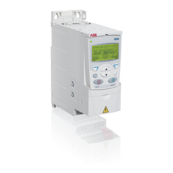
Macros change a group of parameters to new, predefined values. Use macros to minimize the need for manual editing of parameters. HVAC control panel features The ACS320 HVAC control panel (ACH-CP-B) features: 1 Status LED (Green when normal, if flashing or red, see section LEDs on page 381.) -
Page 60: General Display Features
Parameters mode on page for parameter editing instructions. Turning - parameters The system can benefit from one or more of the ACS320 special features, and/or fine tuning. 1. Review the parameter descriptions in section Parameter listing starting on page 148. Enable options and fine tune parameter values as appropriate for the system. - Page 61 Start-up 61 Fault and alarm adjustments The drive can detect a wide variety of potential system problems. For example, initial system operation may generate faults of alarms that indicate set-up problems. 1. Faults and alarms are reported on the control panel with a number. Note the number reported.
-
Page 62: Start-Up
62 Start-up Start-up Start-up can be performed in two ways: • Using the Start-up assistant. CHOICE Do you want to use the start-up assistant? EXIT See section Start-up by using the Start-up assistant. • Changing the parameters individually. See section Start-up by changing the parameters individually. -
Page 63: Start-Up By Changing The Parameters Individually
Start-up 63 Start-up by changing the parameters individually To change the parameters, follow these steps: Select MENU to enter the main 0.0Hz menu. 0 mA MENU Select PARAMETERS with the MAIN MENU UP/DOWN buttons and select PARAMETERS ENTER to select the Parameters ASSISTANTS mode. -
Page 64: Modes
64 Start-up Notes: • The current parameter value appears below the highlighted parameter. • To view the default parameter value, press the UP/DOWN buttons simultaneously. • The most typical and necessary parameters to change belong to Group 99: Start- data, Group 10: Start/Stop/Dir, Group 11: Reference... - Page 65 Start-up 65 Status information Top. The top line of the LCD display shows the basic status information of the drive. • HAND – Indicates that the drive control is local, that is, from the control panel. • AUTO – Indicates that the drive control is remote, such as the basic I/O (X1) or fieldbus.
-
Page 66: Parameters Mode
66 Start-up Operating the drive AUTO/HAND – The very first time the drive is powered up, it is in the auto control (AUTO) mode, and is controlled from the Control terminal block X1. To switch to hand control (HAND) and control the drive using the control panel, press and hold the button. - Page 67 Start-up 67 Select the appropriate parameter PARAMETERS in a group with the UP/DOWN 9901 LANGUAGE buttons. Select EDIT to change 9902 APPLIC MACRO the parameter. HVAC DEFAULT 9905 MOTOR NOM VOLT 9906 MOTOR NOM CURR EXIT EDIT Press the UP/DOWN buttons to PAR EDIT change the parameter value.
-
Page 68: Start-Up Assistant Mode
68 Start-up Start-up assistant mode To start the Start-up assistant, follow these steps: Select MENU to enter the main 0.0Hz menu 0 mA MENU Select ASSISTANTS with the MAIN MENU Up/Down buttons and select PARAMETERS ENTER. ASSISTANTS CHANGED PAR EXIT ENTER Scroll to Commission drive with... - Page 69 Start-up 69 The order of tasks presented by the Start-up assistant depends on your entries. The following task list is typical. Task name Description Spin the motor • Prompts for control panel display language selection. • Prompts for motor data. •...
-
Page 70: Changed Parameters Mode
70 Start-up Changed parameters mode To view (and edit) a listing of all parameters that have been changed from macro default values, follow these steps: Select MENU to enter the menu. 0.0Hz 0 mA MENU Select CHANGED PAR with the MAIN MENU UP/DOWN buttons and select PARAMETERS... - Page 71 Start-up 71 • UPLOAD TO PANEL – Copies all parameters from the drive to the Control panel. This includes user sets of parameters (if defined) and internal parameters. The Control panel memory is non-volatile and does not depend on the panel’s battery. To upload parameters to control panel, follow these steps: Select MENU to enter the main 0.0Hz...
- Page 72 72 Start-up • DOWNLOAD FULL SET – Restores the full parameter set from the Control panel to the drive. Use this option to restore a drive, or to configure identical drives. This download does not include user sets of parameters. To download all parameters to drive, follow these steps: Select MENU to enter the menu.
- Page 73 Start-up 73 • Download application – Copies a partial parameter set from the Control panel to a drive. The partial set does not include internal motor parameters, parameters 9905…9909, 1605, 1607, 5201, nor any Group 53: EFB protocol parameters. Use this option to transfer parameters to systems that use similar configurations –...
- Page 74 74 Start-up Handling inexact downloads In some situations, an exact copy of the download is not appropriate for the target drive. Some examples: • A download to an old drive specifies parameters/values that are not available on the old drive. •...
-
Page 75: Clock Set Mode
Start-up 75 4. Highlight the desired value for the target drive. 5. Press SAVE to save setting. 6. Press EXIT to step back to the differences view and continue for each remaining exception. 7. When your editing is complete, press READY in the Differences List and then select “Yes, save parameters.”... - Page 76 76 Start-up Select CLOCK VISIBILITY with TIME & DATE the UP/DOWN buttons and CLOCK VISIBILITY select SEL to change the TIME FORMAT visibility of the clock. DATE FORMAT SET TIME SET DATE EXIT Scroll to Show clock with the CLOCK VISIB UP/DOWN buttons and select Show clock SEL to make the clock visible.
- Page 77 Start-up 77 Change the days, months and SET DATE year with the UP/DOWN buttons and select OK to save the 01.01.08 values. The active value is displayed in inverted color. CANCEL 00:00 Scroll to DATE FORMAT with the TIME & DATE UP/DOWN buttons and select CLOCK VISIBILITY SEL.
-
Page 78: I/O Settings Mode
78 Start-up I/O settings mode To view and edit the I/O settings, follow these steps: Select MENU to enter the main 0.0Hz menu. 0 mA MENU Scroll to I/O SETTINGS with the MAIN MENU UP/DOWN buttons and select I/O SETTINGS ENTER. -
Page 79: Application Macros
Application macros 79 Application macros Contents of this chapter This chapter describes the application macros. For each macro, there is a wiring diagram showing the default control connections (digital and analog I/O). The chapter also explains how to save a user macro and how to recall it. Overview of macros Application macros are pre-programmed parameter sets. -
Page 80: General Considerations
80 Application macros General considerations The following considerations apply for all macros: • When using a direct speed reference in AUTO mode, connect the speed reference to analog input 1 (AI1), and provide the START command using digital input 1 (DI1). In HAND/OFF mode, the control panel provides the speed reference and START command. -
Page 81: Selecting An Application Macro
Application macros 81 Selecting an application macro To select a macro, follow these steps: Select MENU to enter the main 0.0Hz menu. 0 mA MENU Select ASSISTANTS with the MAIN MENU Up/Down buttons and select PARAMETERS ENTER. ASSISTANTS CHANGED PAR EXIT ENTER Scroll to Commission drive and... -
Page 82: Application / Macro Listing
82 Application macros Application / Macro listing This section describes the following macros: 9902 9902 Macro Macro value value HVAC DEFAULT (page 83) INT TIMER CS (page 91) SUPPLY FAN (page 84) FLOATING PNT (page 92) RETURN FAN (page 85) DUAL SETPPID (page 93) CLNG TWR FAN (page 86) DUAL SP PID WITH CS (page 94) -
Page 83: Hvac Default
Application macros 83 HVAC default This macro provides the factory default parameter settings for the drive. Factory defaults can be restored at any time by setting parameter 9902 APPLIC MACRO to 1. The diagram below shows typical wiring using this macro. When using direct speed reference in AUTO mode or process PID, see section General considerations page 80. -
Page 84: Supply Fan
84 Application macros Supply fan This macro configures for supply fan applications where the supply fan brings fresh air in according to signals received from a transducer. When using direct speed reference in AUTO mode or process PID, see General considerations on page 80. -
Page 85: Return Fan
Application macros 85 Return fan This macro configures for return fan applications where the return fan removes air according to signals received from a transducer. When using direct speed reference in AUTO mode or process PID, see General considerations on page 80. -
Page 86: Cooling Tower Fan
86 Application macros Cooling tower fan This macro configures for cooling tower fan applications where the fan speed is controlled according to the signals received from a transducer. When using direct speed reference in AUTO mode or process PID, see General considerations page 80. -
Page 87: Condenser
Application macros 87 Condenser This macro configures for condenser and liquid cooler applications where fan speed is controlled according to signals received from a transducer. When using direct speed reference in AUTO mode or process PID, see General considerations page 80. -
Page 88: Booster Pump
88 Application macros Booster pump This macro configures for booster pump applications where the pump speed is controlled according to a signal received from a transducer. When using direct speed reference in AUTO mode or process PID, see General considerations on page 80. -
Page 89: Pfa Control Macro
Application macros 89 PFA control macro This macro provides parameter settings for pump and fan alternation (PFA) applications. To enable the macro, set the value of parameter 9902 APPLIC MACRO to 7 (PUMP ALTERNA). Note: Parameter 2108 START INHIBIT must remain in the default setting 0 (OFF). -
Page 90: Internal Timer
90 Application macros Internal timer This macro configures for applications where a built-in timer starts and stops the motor. When the variable speed pump reaches a maximum speed limit, auxiliary pumps start as needed. When using direct speed reference in AUTO mode or process PID, see section General considerations on page 80. -
Page 91: Internal Timer With Constant Speeds / Prv
Application macros 91 Internal timer with constant speeds / PRV This macro configures for applications such as a timed powered roof ventilator (PRV) which alternates between two constant speeds (constant speed 1 and 2) based on a built-in timer. Momentarily activating digital input 3 (DI3) provides a boost function which operates the motor. -
Page 92: Floating Point
92 Application macros Floating point This application macro is for applications where speed reference needs to be controlled through digital inputs (DI4 & DI5). By activating digital input 4, the speed reference increases, by activating digital input 5, the speed reference decreases. If both digital inputs are active or inactive, the reference does not change. -
Page 93: Dual Setpoint With Pid
Application macros 93 Dual setpoint with PID This macro configures for dual setpoint PID applications, where activating digital input 3 (DI3) changes the process PID controller’s setpoint to another value. When using direct speed reference in AUTO mode or process PID, see section General considerations on page 80. -
Page 94: Dual Setpoint With Pid And Constant Speeds
94 Application macros Dual setpoint with PID and constant speeds This macro configures for applications with 2 constant speeds, active PID and PID alternating between two setpoints using digital inputs. Set PID setpoints (internal to the drive) using parameters 4011 ( 1) and 4111 ( 2). -
Page 95: E-Bypass
Application macros 95 E-BYPASS This macro configures for an E-Bypass device which can bypass the drive and connect the motor direct on-line. When using direct speed reference in AUTO mode or process PID, see section General considerations on page 80. Signal cable shield (screen) Not configured AGND... -
Page 96: Hand Control
96 Application macros Hand control This macro configures for drive control using only the control panel with no automated control. Typically, this is a temporary configuration used prior to control wiring. Signal cable shield (screen) External reference 0(2)…10 V or 0(4)…20 mA AGND Analog input circuit common Reference voltage 10 VDC... -
Page 97: E-Clipse
Application macros 97 E-Clipse This macro configures an E-Clipse Bypass device which can bypass the drive and connect the motor direct on-line. When using direct speed reference in AUTO mode or process PID, see section General considerations on page 80. Note: This macro is available only for the UK version. -
Page 98: Modbus Configuration Macro
Service messages requests/responses (acyclic) The AC500 MODBUS application macro default values for the drive parameters correspond to the ABB standard macro (parameter 9902, value 1 (HVAC DEFAULT), see section HVAC default on page 83), with the following differences: Parameters changed relative to HVAC default... -
Page 99: Program Features
Program features 99 Program features Contents of this chapter The chapter describes program features. For each feature, there is a list of related user settings, actual signals, and fault and alarm messages. Start-up assistant Introduction The Start-up assistant (requires the Assistant control panel) guides the user through the start-up procedure, helping to enter the requested data (parameter values) to the drive. -
Page 100: List Of The Tasks And The Relevant Drive Parameters
100 Program features List of the tasks and the relevant drive parameters Depending on the selection made in the Application task (parameter 9902 APPLIC MACRO), the Start-up assistant decides which consequent tasks it suggests. Name Description Set parameters Language select Selecting the language 9901 Motor set-up... -
Page 101: Contents Of The Assistant Displays
Program features 101 Name Description Set parameters Timed functions Setting the timed functions Group 36: Timed functions Selecting the timed start/stop control for 1001, 1002 external control locations EXT1 and EXT2 Selecting timed EXT1/EXT2 control 1102 Activation of timed constant speed 1 1201 Selecting timed function status indicated 1401... -
Page 102: Local Control Vs. External Control
102 Program features Local control vs. external control The drive can receive start, stop and direction commands and reference values from the control panel or through digital and analog inputs. Embedded fieldbus enables control over an open fieldbus link. A PC equipped with DriveWindow Light PC tool can also control the drive. -
Page 103: External Control
Program features 103 External control When the drive is in external control, the commands are given through the standard I/O terminals (digital and analog inputs) and/or the fieldbus interface. In addition, it is also possible to set the control panel as the source for the external control. External control is indicated with REM on the panel display. -
Page 104: Block Diagram: Start, Stop, Direction Source For Ext1
104 Program features Block diagram: Start, stop, direction source for EXT1 The figure below shows the parameters that select the interface for start, stop, and direction for external control location EXT1. Select EXT1 Start/stop/ direction Fieldbus selection See chapter COMM Fieldbus control Embedded fieldbus... -
Page 105: Reference Types And Processing
Program features 105 Reference types and processing The drive can accept a variety of references in addition to the conventional analog input and control panel signals. • The drive reference can be given with two digital inputs: One digital input increases the speed, the other decreases it. -
Page 106: Reference Trimming
106 Program features Reference trimming In reference trimming, the external reference is corrected depending on the measured value of a secondary application variable. The block diagram below illustrates the function. Switch Select 1105 REF1 MAX / DIRECT (2) 1108 REF 2 MAX REF1 (Hz/rpm) / PROPOR. -
Page 107: Programmable Analog Inputs
Program features 107 Programmable analog inputs The drive has two programmable analog voltage/current inputs. The inputs can be inverted, filtered and the maximum and minimum values can be adjusted. The update cycle for the analog input is 8 ms (12 ms cycle once per second). The cycle time is shorter when information is transferred to the application program (8 ms ->... -
Page 108: Programmable Analog Output
108 Program features Programmable analog output One programmable current output (0 … 20 mA) is available. Analog output signal can be inverted, filtered and the maximum and minimum values can be adjusted. The analog output signals can be proportional to motor speed, output frequency, output current, motor torque, motor power, etc. -
Page 109: Programmable Digital Inputs
Program features 109 Programmable digital inputs The drive has five programmable digital inputs. The update time for the digital inputs is 2 ms. It is possible to delay the state change of digital inputs with delays defined in group . This enables very simple program sequences by Group 18: Freq in &... -
Page 110: Diagnostics
110 Program features Diagnostics Actual signal Additional information 0160 DI status 0414 DI status at the time the latest fault occurred Programmable relay output The drive has one programmable relay output. It is possible to add three additional relay outputs with the optional MREL-0 relay output extension module. For more information, see MREL-01 output relay module user’s manual (3AUA0000035974 [English]). -
Page 111: Frequency Input
Program features 111 Frequency input Digital input DI5 can be programmed as a frequency input. Frequency input (0…16000 Hz) can be used as external reference signal source. The update time for the frequency input is 50 ms. Update time is shorter when information is transferred to the application program (50 ms ->... -
Page 112: Actual Signals
112 Program features Actual signals Several actual signals are available: • Drive output frequency, current, voltage and power • Motor speed and torque • Intermediate circuit DC voltage • Active control location (LOCAL, EXT1 or EXT2) • Reference values • Drive temperature •... -
Page 113: Power Loss Ride-Through
Program features 113 Power loss ride-through If the incoming supply voltage is cut off, the drive will continue to operate by utilizing the kinetic energy of the rotating motor. The drive will be fully operational as long as the motor rotates and generates energy to the drive. The drive can continue the operation after the break if the main contactor remained closed. -
Page 114: Maintenance Trigger
114 Program features Maintenance trigger A maintenance trigger can be activated to show a notice on the panel display when, for example, drive power consumption has exceeded the defined trigger point. Settings Parameter Group 29: Maintenance trig Acceleration and deceleration ramps Two user-selectable acceleration and Motor speed deceleration ramps are available. -
Page 115: Critical Speeds
Program features 115 Critical speeds A Critical Speeds function is available for applications where it is necessary to avoid certain motor speeds (drive output frequencies) or speed bands (output frequency bands) because of, for example, mechanical resonance problems. The user can define three critical frequencies or frequency bands. -
Page 116: Custom U/F Ratio
116 Program features Custom U/f ratio The user can define a U/f curve (output voltage as a function of frequency). This custom ratio is used only in special applications where linear and squared U/f ratio are not sufficient (eg, when motor break-away torque needs to be boosted). Voltage (V) Custom U/f ratio par. -
Page 117: R Compensation
Program features 117 R compensation When IR compensation is activated, the drive Motor voltage gives an extra voltage boost to the motor at low speeds. IR compensation is useful in IR compensation applications that require high breakaway torque. Settings No compensation Parameter 2603 IR COMP VOLT... -
Page 118: Motor Thermal Protection
118 Program features Motor thermal protection The motor can be protected against overheating by activating the Motor thermal protection function. The drive calculates the temperature of the motor on the basis of the following assumptions: 1. The motor is in the ambient temperature of 30 °C when power is applied to the drive. -
Page 119: Incorrect Wiring
Program features 119 Incorrect wiring Defines the operation when incorrect input power cable connection is detected. Settings Parameter 3023 WIRING FAULT Preprogrammed faults Overcurrent The overcurrent trip limit for the drive is 325% of the drive nominal current. ... -
Page 120: Power Limit
120 Program features Power limit Power limitation is used to protect the input bridge and the DC intermediate circuit. If the maximum allowed power is exceeded, the drive torque is automatically limited. Maximum overload and continuous power limits depend on the drive hardware. For specific values, see chapter Technical data on page 383. -
Page 121: Parameter Lock
Program features 121 Parameter lock The user can prevent parameter adjustment by activating the parameter lock. Settings Parameters 1602 PARAMETER LOCK 1603 PASS CODE PID control There are two built-in PID controllers in the drive: • Process PID (PID1) and •... -
Page 122: Block Diagrams
122 Program features Block diagrams The figure below shows an application example: The controller adjusts the speed of a pressure boost pump according to the measured pressure and the set pressure reference. Example: PID control block diagram Pressure boost pump %ref A C S 6 0 0 Drive... - Page 123 Program features 123 The following figure presents the speed/scalar control block diagram for process controller PID1.
-
Page 124: Settings
124 Program features Settings Parameter Additional information 1101 Local control mode reference type selection 1102 EXT1/2 selection 1106 PID1 activation 1107 REF2 minimum limit 1501 PID2 output (external controller) connection to AO 9902 PID control macro selection Group 40: Process PID set PID1 settings 1…Group 41: Process PID set 2 Group 42: Ext / Trim PID... -
Page 125: Sleep Function For The Process Pid (Pid1) Control
Program features 125 Sleep function for the process PID (PID1) control The sleep function operates on a 2 ms time level. The block diagram below illustrates the sleep function enable/disable logic. The sleep function can be put into use only when the PID control is active. Compare Select NOT SEL... -
Page 126: Example
126 Program features Example The time scheme below visualizes the operation of the sleep function. Reference Sleep boost time (4030) Sleep boost step (4031) Time Wake-up delay Selected process (4026) actual value Wake-up level deviation (4025) Time Output frequency Control panel: = Sleep delay (4024) SLEEP... -
Page 127: Settings
Program features 127 Settings Parameter Additional information 9902 PID control activation 4022…4026, 4030, 4031, Sleep function settings 4122…4126, 4130, 4131 Diagnostics Parameter Additional information 1401 PID sleep function status through RO 1 1402/1403/1410 PID sleep function status through RO 2…4. With option MREL-01 only. - Page 128 128 Program features To fulfill the insulation requirement, connect a thermistor (and other similar components) to the drive’s control terminals using any of these alternatives: • Separate the thermistor from live parts of the motor with double reinforced insulation. • Protect all circuits connected to the drive’s digital and analog inputs. Protect against contact, and insulate from other low voltage circuits with basic insulation (rated for the same voltage level as the drive’s main circuit).
-
Page 129: Settings
Program features 129 Settings Parameter Additional information Group 13: Analogue inputs Analog input settings Group 15: Analogue outputs Analog output settings Group 35: Motor temp meas Motor temperature measurement settings Other At the motor end the cable shield should be grounded through a 10 nF capacitor. If this is not possible, the shield is to be left unconnected. -
Page 130: Timed Functions
130 Program features Timed functions A variety of drive functions can be time controlled, eg start/stop and EXT1/EXT2 control. The drive offers • four start and stop times (START TIME 1…4, STOP TIME 1…4) • four start and stop days (START DAY 1…4, STOP DAY 1…4) •... -
Page 131: Examples
Program features 131 A parameter which is triggered by a timed function can be connected to only one timed function at a time. 1001 EXT 1 COMMANDS Timed func 1 1002 EXT 2 COMMANDS 3626 TIMED FUNC 1 SRC 11021201 CONST SPEED SEL 1209 TIME MODE SEL Timed func 2 1401 RELAY OUTPUT 1... -
Page 132: User Load Curve
132 Program features Parameter Additional information 1805 Timed function status indicated through digital output DO 4027 Timed PID1 parameter set 1/2 selection 4228 Timed external PID2 activation User load curve The user can specify a load curve (motor torque as a function of frequency) for supervision. -
Page 133: Diagnostics
Program features 133 Diagnostics Actual signal Additional information 0105 Motor torque Alarm USER LOAD CURVE Out of allowed area for longer than half of the defined time limit Fault USER LOAD CURVE Out of allowed area for longer than the defined time limit PAR USER LOAD C Incorrect user load curve parameter setting... -
Page 134: Energy Saving
134 Program features Energy saving Energy saving tools calculate energy saved in kWh and MWh, energy saved in local currency as well as reduction in CO emission, all compared to the situation when the pump is connected directly to the supply. Two actual signals, 0176 SAVED AMOUNT 1 0177 SAVED AMOUNT 2... -
Page 135: Pump Cleaning
Program features 135 Pump cleaning The Pump cleaning function can be used for preventing solids from building up on pump impellers. The function consists of a programmable sequence of forward and reverse runs of the pump (see the figure below), effectively shaking off any residue on the impeller. -
Page 136: Load Analyzer
136 Program features Load analyzer The load analyzer can be used for analyzing the customer’s process and sizing the drive and the motor. Peak value logger The user can select a signal (Group 01: Operating data) to be monitored by the peak value logger (PVL). -
Page 137: Settings
Program features 137 Settings Parameter Additional information Group 64: Load analyzer, Load analyzer settings parameters 6401…6405 Diagnostics Actual signal Additional information Group 64: Load analyzer, Load analyzer results parameters 6406…6433 PFA control (Requires use of MREL-01 option purchased separately) ... -
Page 138: Spfc Control
138 Program features An Autochange function (when enabled and with the appropriate switchgear) equalizes duty time between the pump motors. Autochange periodically increments the position of each motor in the rotation – the speed regulated motor becomes the last auxiliary motor, the first auxiliary motor becomes the speed regulated motor, etc. When the speed regulated motor reaches the full output, it is disconnected from the drive and switched to direct on-line connection, with a slight delay in between. - Page 139 Program features 139 SPFC powering routine The diagram below illustrates the SPFC powering routine. 8109 START FREQ 1 Motor 1 is speed reg. motor Motor 2 is speed reg. motor Motor 1 is aux. motor Start RO 1 / Motor 1 RO 2 / Motor 2 8122 PFA START DELAY 8122 PFA START DELAY...
-
Page 140: Settings
140 Program features How to parameterize SPFC control 1. Set PFA reference steps (parameters 8103…8105) if needed. 2. Set PFA start and stop frequencies (parameters 8109…8114). 3. Set PFA auxiliary motor start and stop delays (parameters 8115…8116). 4. Set the number of auxiliary motors (parameter 8117). 5. -
Page 141: Diagnostics
Program features 141 Parameter Additional information Group 81: PFA control; 8123 PFA PFA control settings; Enables PFA/SPFC function. ENABLE Diagnostics Actual signal Additional information 0116 Application block output signal 0162 RO 1 status 0163 TO status 0173 RO 2…4 status. With option MREL-01 only. Alarm AUTOCHANGE PFA autochange function active... -
Page 142: Connection Diagram Example
142 Program features Connection diagram example... -
Page 143: Actual Signals And Parameters
Actual signals and parameters 143 Actual signals and parameters Contents of this chapter The chapter describes the actual signals and parameters and gives the fieldbus equivalent values for each signal/parameter. It also contains a table of the default values for the different macros. Note: When the control panel is in the short parameter view, in other words, when parameter 1611 PARAMETER VIEW... -
Page 144: Terms And Abbreviations
144 Actual signals and parameters Terms and abbreviations Term Definition Actual signal Signal measured or calculated by the drive. Can be monitored by the user. No user setting possible. Group 01: Operating data…Group 04: Fault history contain actual signals. Parameter default value Refers to types 03E- with European parametrization FbEq Fieldbus equivalent: The scaling between the value and the integer used in... -
Page 145: Parameters In The Short Parameter View
Actual signals and parameters 145 Parameters in the short parameter view Parameters in the short parameter view Name/Value Description Default 11 REFERENCE Panel reference type, external control location selection SELECT and external reference sources and limits. See Group 11: Reference select in the list of all parameters. - Page 146 For Modbus: Sets an additional delay before the drive begins transmitting response to the master request. 5319 EFB PAR 19 ABB drives profile (ABB DRV LIM or ABB DRV FULL) 0000 hex Control word. Read only copy of the Fieldbus Control...
- Page 147 Parameters in the short parameter view Name/Value Description Default 5320 EFB PAR 20 ABB drives profile (ABB DRV LIM or ABB DRV FULL) 0000 hex Status word. Read only copy of the Fieldbus Status word. 98 OPTIONS External serial communication activation.
-
Page 148: Parameter Listing
148 Actual signals and parameters Parameter listing Parameter data is specific to ACS320 firmware version 4.01C. Group 99: Start-up data This group defines special Start-up data required to: • set up the drive • enter motor information. Note: Parameters checked under the heading “S” can be modified only when the drive is stopped. - Page 149 Actual signals and parameters 149 Group 99: Start-up data Code Description Range Resolution Default 9907 MOTOR NOM FREQ 10.0 … 500 Hz 0.1 Hz 60 Hz (US) Defines the nominal motor frequency. • Range: 10 … 500 Hz (typically 50 or 60 Hz) •...
-
Page 150: Group 01: Operating Data
150 Actual signals and parameters Group 01: Operating data This group contains drive operating data, including actual signals. The drive sets the values for actual signals, based on measurements or calculations. You cannot set these values. Group 01: Operating data Code Description Range... - Page 151 Actual signals and parameters 151 Group 01: Operating data Code Description Range Resolution Default 0115 KWH COUNTER (R) 0 … 10000 h The drive’s accumulated power consumption in kilowatt hours. • Can be reset by pressing UP and DOWN buttons simultaneously when in parameter set mode.
- Page 152 152 Actual signals and parameters Group 01: Operating data Code Description Range Resolution Default 0134 COMM RO WORD 0...65535 Free data location that can be written from serial link. • Used for relay output control. • See parameter 1401. 0135 COMM VALUE 1 -32768 …...
- Page 153 Actual signals and parameters 153 Group 01: Operating data Code Description Range Resolution Default 0159 PID COMM VALUE 2 Data received from fieldbus for PID control (PID1 and PID2). DI 1-5 STATUS 0160 Status of digital inputs. Example: 10000 = DI1 is on, DI2...DI5 are off. 0161 PULSE INPUT FREQ 1 = 1 Hz...
- Page 154 154 Actual signals and parameters Group 01: Operating data Code Description Range Resolution Default 0176 SAVED AMOUNT 1 0.0 … 999.9 Energy saved in local currency (remainder when the total saved energy is divided by 1000). See the note on page 251. •...
-
Page 155: Group 03: Fb Actual Signals
Actual signals and parameters 155 Group 03: FB actual signals This group monitors fieldbus communications. Group 03: FB actual signals Code Description Range Resolution Default 0301 FB CMD WORD 1 Read-only copy of the Fieldbus command word 1. • The fieldbus command is the principal means for controlling the drive from a fieldbus controller. - Page 156 156 Actual signals and parameters Group 03: FB actual signals Code Description Range Resolution Default 0303 FB STS WORD 1 - hex Read-only copy of the Status word 1. • The drive sends status information to the fieldbus controller. The status consists of two Status words.
- Page 157 Actual signals and parameters 157 Group 03: FB actual signals Code Description Range Resolution Default 0305 FAULT WORD 1 0000 hex Read-only copy of the Fault word 1. • When a fault is active, the corresponding bit for the active fault is set in the Fault words.
- Page 158 158 Actual signals and parameters Group 03: FB actual signals Code Description Range Resolution Default 0308 ALARM WORD 1 0000 hex Read-only copy of the ALARM WORD 1. • When a fault is active, the corresponding bit for the active fault is set in the Fault words.
-
Page 159: Group 04: Fault History
Actual signals and parameters 159 Group 04: Fault history This group stores a recent history of the faults reported by the drive. Group 04: Fault history Code Description Range Resolution Default 0401 LAST FAULT Fault code text 0 = Clear the fault history (on panel = NO RECORD). n = Fault code of the last recorded fault. -
Page 160: Group 10: Start/Stop/Dir
160 Actual signals and parameters Group 10: Start/Stop/Dir This group: • Defines external sources (EXT1, and EXT2) for commands that enable start, stop and direction changes. • Locks direction or enables direction control. To select between the two external locations use the next group, parameter 1102 EXT1/EXT2 SEL. - Page 161 Actual signals and parameters 161 Group 10: Start/Stop/Dir Code Description Range Resolution Default 5 = DI1P, 2P, 3P – Start Forward, Start Reverse, and Stop. • Start and Direction commands are given simultaneously with two separate momentary push-buttons (the P stands for “pulse”). •...
-
Page 162: Group 11: Reference Select
162 Actual signals and parameters Group 10: Start/Stop/Dir Code Description Range Resolution Default 1002 EXT2 COMMANDS 0...34 Defines external control location 2 (EXT2) – the configuration of start, stop and direction commands. • See parameter 1001 EXT1 COMMANDS above. 1003 DIRECTION 1...3... - Page 163 Actual signals and parameters 163 Group 11: Reference select Code Description Range Resolution Default KEYPAD REF SEL 1101 Selects the reference controlled in local control mode. 1 = REF1 (Hz/rpm) – Frequency reference in Hz. 2 = REF2 (%) – %-reference. EXT1/EXT2 SEL 1102 -5...12...
- Page 164 164 Actual signals and parameters Group 11: Reference select Code Description Range Resolution Default 1103 REF1 SELECT 0...32 Selects the signal source for external reference REF1. 0 = KEYPAD – Defines the control panel as the reference source. 1 = AI1 – Defines analog input 1 (AI1) as the reference source. 2 = AI2 –...
- Page 165 Actual signals and parameters 165 Group 11: Reference select Code Description Range Resolution Default 4 = AI2/JOYST – Defines analog input 2 (AI2), configured for joystick operation, as the reference source. • See above (AI1/JOYST) description. 5 = DI3U,4D(R) – Defines digital inputs as the speed reference source (motor potentiometer control).
- Page 166 166 Actual signals and parameters Group 11: Reference select Code Description Range Resolution Default Analog Input Reference Correction Parameter values 9, 10, and 14…17 use the formula in the following table. Value setting Calculation of the AI reference C + B C value + (B value - 50% of reference value) C * B C value * (B value / 50% of reference value)
- Page 167 Actual signals and parameters 167 Group 11: Reference select Code Description Range Resolution Default 1104 REF1 MIN 0.0 … 500.0 Hz 0.1 Hz 0.0 Hz Sets the minimum for external reference 1. • The minimum analog input signal (as a percent of the full signal in volts or amps) corresponds to REF1 MIN in Hz/rpm.
-
Page 168: Group 12: Constant Speeds
168 Actual signals and parameters Group 11: Reference select Code Description Range Resolution Default 1107 REF2 MIN 0.0 … 100.0% 0.1% 0.0% (torque: 0 … 600%) Sets the minimum for external reference 2. • The minimum analog input signal (in volts or amps) corresponds to REF2 MIN in %. •... - Page 169 Actual signals and parameters 169 Group 12: Constant speeds Code Description Range Resolution Default CONST SPEED SEL 1201 -13…19 Defines the digital inputs used to select Constant speeds. See general comments in the introduction. 0 = NOT SEL – Disables the constant speed function. 1 = DI1 –...
- Page 170 170 Actual signals and parameters Group 12: Constant speeds Code Description Range Resolution Default 15…18 = TIMER – Selects constant speed 1, constant speed 2 or the external reference depending on the state of, eg, timer 1 (if the parameter value is 15 = TIMER 1), timer 3 (if the parameter value is 17 = TIMER 3) etc, and the constant speed mode.
- Page 171 Actual signals and parameters 171 Group 12: Constant speeds Code Description Range Resolution Default -12 = DI1,2,3(INV) – Selects one of seven constant speeds (1...7) using DI1, DI2 and DI3. • Inverse operation uses three digital inputs, as defined below (0 = DI de-activated, 1 = DI activated): Function No constant speed...
- Page 172 172 Actual signals and parameters Group 12: Constant speeds Code Description Range Resolution Default 1209 TIMED MODE SEL 1…2 Defines timer activated, constant speed mode. Timer can be used to change between external reference and a maximum of three constant speeds, or to change between a maximum of 4 selectable speeds, in other words, constant speeds 1,2,3 and 4.
-
Page 173: Group 13: Analogue Inputs
Actual signals and parameters 173 Group 13: Analogue inputs This group defines the limits and the filtering for analog inputs. Group 13: Analogue inputs Code Description Range Resolution Default 1301 MINIMUM AI1 -100.0 … 100.0% 0.1% 20.0% Defines the minimum value of the analog input. •... -
Page 174: Group 14: Relay Outputs
174 Actual signals and parameters Group 14: Relay outputs This group defines the condition that activates each of the relay outputs. Group 14: Relay outputs Code Description Range Resolution Default 1401 RELAY OUTPUT 1 0…69 Defines the event or condition that activates relay 1 – what relay output 1 means. 0 = NOT SEL –... - Page 175 Actual signals and parameters 175 Group 14: Relay outputs Code Description Range Resolution Default 20 = REF LOSS – Energize relay when reference or active control place is lost. 21 = OVERCURRENT – Energize relay when an overcurrent alarm or fault occurs. 22 = OVERVOLTAGE –...
- Page 176 176 Actual signals and parameters Group 14: Relay outputs Code Description Range Resolution Default 36 = COMM(-1) – Energize relay based on input from fieldbus communication. • Fieldbus writes binary code in parameter 0134 that can energizes relay 1…relay 4 according to the following: Parameter Binary 0134...
- Page 177 Actual signals and parameters 177 Group 14: Relay outputs Code Description Range Resolution Default 1404 RO 1 ON DELAY 0.0 … 3600.0 s 0.1 s 0.0 s Defines the switch-on delay for relay 1. Control event • On / off delays are ignored when relay output of parameter 1401 RELAY OUTPUT 1...
-
Page 178: Group 15: Analogue Outputs
178 Actual signals and parameters Group 15: Analogue outputs This group defines the drive’s analog (current signal) outputs. The drive’s analog outputs can be: • Any parameter of Group 01: Operating data. • Limited to programmable minimum and maximum values of output current. •... -
Page 179: Group 16: System Controls
Actual signals and parameters 179 Group 15: Analogue outputs Code Description Range Resolution Default 1503 AO1 CONTENT MAX Depends on selection 60.0 Sets the maximum content value • Content is the parameter selected by parameter 1501 AO1 CONTENT SEL. • Maximum value refers to the maximum content value that will be converted to an analog output. - Page 180 180 Actual signals and parameters Group 16: System controls Code Description Range Resolution Default 1602 PARAMETER LOCK 0…2 Determines if the control panel can change parameter values. • This lock does not limit parameter changes made by macros. • This lock does not limit parameter changes written by fieldbus inputs. •...
- Page 181 Actual signals and parameters 181 Group 16: System controls Code Description Range Resolution Default 1605 USER PAR SET CHG -5…5 Defines control for changing the user parameter set. • See parameter 9902 APPLIC MACRO. • The drive must be stopped to change User parameter sets. •...
- Page 182 182 Actual signals and parameters Group 16: System controls Code Description Range Resolution Default 1606 LOCAL LOCK -5…8 Defines control for the use of the HAND mode. The HAND mode allows drive control from the control panel. • When LOCAL LOCK is active, the control panel cannot change to HAND mode. 0 = NOT SEL –...
- Page 183 Actual signals and parameters 183 Group 16: System controls Code Description Range Resolution Default 1608 START ENABLE 1 -5…7 Selects the source of the start enable 1 signal. Note: Start enable functionality differs from the run enable functionality. 0 = NOT SEL – Allows the drive to start without an external start enable signal. 1 = DI1 –...
- Page 184 184 Actual signals and parameters Group 16: System controls Code Description Range Resolution Default 1609 START ENABLE 2 -5…7 Selects the source of the start enable 2 signal. Note: Start enable functionality differs from the run enable functionality. 0 = NOT SEL – Allows the drive to start without an external start enable signal. 1 = DI1 –...
-
Page 185: Group 17: Override
Actual signals and parameters 185 Group 17: Override This group defines the source for the override activation signal, the override speed/ frequency and pass code and how the override is enabled and disabled. When override DI is activated, the drive stops and then accelerates to the preset speed or frequency. - Page 186 186 Actual signals and parameters EFB 2 EFB 3 MOTOR PHASE 1001 PAR PFA REF NEG 1002 PAR PFC IOCONF 1003 PAR AI SCALE 1004 PAR AO SCALE 1006 PAR EXT RO 1007 PAR FIELDBUS MISSING 1008 PAR PFA MODE Commissioning the override mode 1.
- Page 187 Actual signals and parameters 187 Group 17: Override Code Description Range Resolution Default OVERRIDE SEL 1701 -5…5 Selects the source of the override activation signal. 0 = NOT SEL – Override activation signal not selected. 1 = DI1 – Defines digital input DI1 as the override activation signal. •...
-
Page 188: Group 18: Freq In & Tran Out
188 Actual signals and parameters Group 17: Override Code Description Range Resolution Default 1707 OVERRIDE REF Selects the source of the override reference. 1 = CONSTANT – Selects a preset frequency or speed for the override. The frequency value is defined by parameter 1702 OVERRIDE FREQ. - Page 189 Actual signals and parameters 189 Group 18: Freq in & tran out Code Description Range Resolution Default 1809 FO CONTENT MIN Defines the minimum frequency output FO signal value. Signal is selected with parameter 1808 FO CONTENT SEL. FO minimum and maximum correspond to 1811 MINIMUM FO 1812 MAXIMUM settings as follows:...
- Page 190 190 Actual signals and parameters Group 18: Freq in & tran out Code Description Range Resolution Default 1820 DI 4 ON DELAY 0.0 s See parameter 1814 DI 1 ON DELAY. DI 4 OFF DELAY 1821 0.0 s See parameter 1815 DI 1 OFF DELAY.
-
Page 191: Group 20: Limits
Actual signals and parameters 191 Group 20: Limits This group defines minimum and maximum limits to follow in driving the motor – speed, frequency, current, torque, etc. Group 20: Limits Code Description Range Resolution Default MAX CURRENT 2003 0.0 …... -
Page 192: Group 21: Start/Stop
192 Actual signals and parameters Group 21: Start/Stop This group defines how the motor starts and stops. The drive supports several start and stop modes. Group 21: Start/Stop Code Description Range Resolution Default START FUNCTION 2101 1…7 Selects the motor start method. 1 = AUTO –... - Page 193 Actual signals and parameters 193 Group 21: Start/Stop Code Description Range Resolution Default 2103 DC MAGN TIME 0.00 … 10.00 s 0.01 s 0.30 s Defines the pre-magnetizing time for the DC Magnetizing start mode. • Use parameter 2101 START FUNCTION to select the start mode.
- Page 194 194 Actual signals and parameters Group 21: Start/Stop Code Description Range Resolution Default 2109 EMERG STOP SEL -5…5 Defines control of the Emergency stop command. When activated: • Emergency stop decelerates the motor using the emergency stop ramp (parameter 2208 EMERG DEC TIME).
-
Page 195: Group 22: Accel/Decel
Actual signals and parameters 195 Group 21: Start/Stop Code Description Range Resolution Default 2115 MOT. HEATING SEL -5...8 Selects the source for controlling motor heating. -5...-1 = DI1 (INV)...DI5 (INV) – Inverted digital input DI. (0 = Motor heating is On, 1 = Motor heating is Off). - Page 196 196 Actual signals and parameters Group 22: Accel/Decel Code Description Range Resolution Default 2203 DECELER TIME 1 0.0 … 1800.0 s 0.1 s 30.0 s Sets the deceleration time for maximum frequency to zero for ramp pair 1. • Actual deceleration time also depends on parameter 2204 RAMP SHAPE •...
- Page 197 Actual signals and parameters 197 Group 22: Accel/Decel Code Description Range Resolution Default 2209 RAMP INPUT 0 -5…5 Defines control for forcing the ramp input to 0. 0 = NOT SEL – Not selected. 1 = DI1 – Defines digital input 1 as the control for forcing the ramp input to 0. •...
-
Page 198: Group 25: Critical Speeds
198 Actual signals and parameters Group 25: Critical speeds This group defines up to three critical speeds or ranges of speeds that are to be avoided due, for example, to mechanical resonance problems at certain speeds. Group 25: Critical speeds Code Description Range... -
Page 199: Group 26: Motor Control
Actual signals and parameters 199 Group 25: Critical speeds Code Description Range Resolution Default 2507 CRIT SPEED 3 HI 0.0 … 500.0 Hz 0.1 Hz 0.0 Hz Sets the maximum limit for critical speed range 3. • See parameter 2503 CRIT SPEED 1 ... - Page 200 200 Actual signals and parameters Group 26: Motor control Code Description Range Resolution Default 2606 SWITCHING FREQ 1, 4, 8, 12, 16 kHz 4 kHz Defines the switching frequency of the drive. Higher switching frequency results in lower acoustic noise in the motor. See also parameter 2207 SWITCH FREQ CTRL and section Switching frequency...
- Page 201 Actual signals and parameters 201 Group 26: Motor control Code Description Range Resolution Default 2609 NOISE SMOOTHING 0, 1 Enables the noise smoothing function. Noise smoothing distributes the acoustic motor noise over a range of frequencies instead of a single tonal frequency resulting in lower peak noise intensity.
-
Page 202: Group 29: Maintenance Trig
202 Actual signals and parameters Group 29: Maintenance trig This group contains usage levels and trigger points. When usage reaches the set trigger point, a notice is displayed on the control panel signals that maintenance is due. Group 29: Maintenance trig Code Description Range... -
Page 203: Group 30: Fault Functions
Actual signals and parameters 203 Group 29: Maintenance trig Code Description Range Resolution Default 2907 USER MWh TRIG 0.0 … 6553.5 MWh 0.1 MWh Defines the trigger point for the drive power consumption counter. Value is compared to the value of parameter 2908 USER MWh ACT. - Page 204 204 Actual signals and parameters Group 30: Fault functions Code Description Range Resolution Default 3002 PANEL COMM ERR 1…3 Defines the drive response to a control panel communication error. Note: When either of the two external control locations are active, and start, stop and/or direction are through the control panel –...
- Page 205 Actual signals and parameters 205 Group 30: Fault functions Code Description Range Resolution Default 3006 MOT THERM TIME 256 … 9999 s 1050 s Sets the motor thermal time Motor load constant for the motor temperature model. • This is the time required for the motor to reach 63% of the final temperature with steady load.
- Page 206 206 Actual signals and parameters Group 30: Fault functions Code Description Range Resolution Default 3009 BREAK POINT 1 … 250 Hz 35 Hz FREQ Defines the load curve together with parameters 3007 MOT LOAD CURVE 3009 BREAK POINT FREQ. Example: Thermal protection trip times when parameters 3006 MOT THERM TIME, 3007 MOT LOAD CURVE...
- Page 207 Actual signals and parameters 207 Group 30: Fault functions Code Description Range Resolution Default 3016 SUPPLY PHASE Selects how the drive reacts to a supply phase loss, in other words, when the DC voltage ripple is excessive. 0 = FAULT – Drive trips on fault SUPPLY PHASE and the motor coasts to stop when the DC voltage ripple exceeds 14% of the nominal DC voltage.
-
Page 208: Group 31: Automatic Reset
208 Actual signals and parameters Group 30: Fault functions Code Description Range Resolution Default 3023 WIRING FAULT 0, 1 Selects how the drive reacts when incorrect input power and motor cable connection is detected (ie, the input power cable is connected to the motor connection of the drive). - Page 209 Actual signals and parameters 209 Group 31: Automatic reset Code Description Range Resolution Default 3104 AR OVERCURRENT 0, 1 Sets the automatic reset for the overcurrent function on or off. 0 = DISABLE – Disables automatic reset. 1 = ENABLE – Enables automatic reset. •...
-
Page 210: Group 32: Supervision
210 Actual signals and parameters Group 32: Supervision This group defines supervision for up to three signals from Group 01: Operating data. Supervision monitors a specified parameter and energizes a relay output if the parameter passes a defined limit. Use Group 14: Relay outputs, to define the relay and whether the relay activates when the signal is too low or too high. - Page 211 Actual signals and parameters 211 Group 32: Supervision Code Description Range Resolution Default LO > HI Value of supervised parameter Active limit Operating data supervision using relay LO (3202) outputs, when LO > HI. HI (3203) The lowest limit (HI 3203) is active initially, and remains active until the supervised parameter...
-
Page 212: Group 33: Information
212 Actual signals and parameters Group 32: Supervision Code Description Range Resolution Default 3208 SUPERV 3 LIM LO Depends on selection 100.0 Sets the low limit for the third supervised parameter. See parameter 3207 SUPERV 3 PARAM above. Supervision wakes up if the value is below the limit. SUPERV 3 LIM HI 3209 Depends on selection... -
Page 213: Group 34: Panel Display
Actual signals and parameters 213 Group 34: Panel display This group defines the content for control panel display (middle area), when the control panel is in the Output mode. Group 34: Panel display Code Description Range Resolution Default SIGNAL1 PARAM 3401 101…178 Selects the first parameter (by number) - Page 214 214 Actual signals and parameters Group 34: Panel display Code Description Range Resolution Default 3404 OUTPUT1 DSP 0…9 FORM Defines the decimal point location for the first 3404 value Display Range display parameter. -32768…+32767 1…7 – Defines the decimal point location. (Signed) + 3.1 •...
- Page 215 Actual signals and parameters 215 Group 34: Panel display Code Description Range Resolution Default 3407 OUTPUT1 MAX Depends on selection Sets the maximum value displayed for the first display parameter. Note: Parameter is not effective if parameter 3404 OUTPUT1 DSP FORM (DIRECT).
- Page 216 216 Actual signals and parameters Group 34: Panel display Code Description Range Resolution Default 3419 OUTPUT3 UNIT 0…127 Selects the units used with the third display parameter. See parameter 3405 OUTPUT1 UNIT. OUTPUT3 MIN 3420 Depends on selection Sets the minimum value displayed for the third display parameter. See parameter 3406 OUTPUT1 MIN.
-
Page 217: Group 35: Motor Temp Meas
Actual signals and parameters 217 Group 35: Motor temp meas Group 35: Motor temp meas Code Description Range Resolution Default 3501 SENSOR TYPE 0…6 Activates the motor temperature measurement function and selects the sensor type. See also parameter Group 15: Analogue outputs. -
Page 218: Group 36: Timed Functions
218 Actual signals and parameters Group 35: Motor temp meas Code Description Range Resolution Default 3502 INPUT SELECTION 1…7 Selects the source for the motor temperature measurement signal. 1 = AI1 – Analog input AI1. Used when Pt100 or PTC sensor is selected for the temperature measurement. - Page 219 Actual signals and parameters 219 Time period 1 3602 START TIME 1 3603 STOP TIME 1 3604 START DAY 1 3605 STOP DAY 1 Time period 2 Timer 1 3606 START TIME 2 3626 TIMER 1 SRC 3607 STOP TIME 2 3608 START DAY 2 Timer 2 3609 STOP DAY 2...
- Page 220 220 Actual signals and parameters Group 36: Timed functions Code Description Range Resolution Default TIMERS ENABLE 3601 -15…17 Selects the source for the timer enable signal. 0 = NOT SEL – Timed functions are disabled. 1 = DI1 – Defines digital input DI1 as the timed function enable signal. •...
- Page 221 Actual signals and parameters 221 Group 36: Timed functions Code Description Range Resolution Default 3604 START DAY 1 1…7 Defines the weekly start day. 1 = MONDAY…7 = SUNDAY. • If parameter value is 1, then period 1 weekly is active from Monday midnight (00:00:00).
- Page 222 222 Actual signals and parameters Group 36: Timed functions Code Description Range Resolution Default 3616 START DAY 4 1…7 Defines timer 4 weekly start day. • See parameter 3604 START DAY 3617 STOP DAY 4 1…7 Defines timer 4 weekly stop day. •...
- Page 223 Actual signals and parameters 223 Group 36: Timed functions Code Description Range Resolution Default 3626 TIMER 1 SRC 0…48 Defines the time periods used by the timer. 0 = NOT SEL- No timers have been selected. 1 = P1 – Time Period 1 selected in the timer. 2 = P2 –...
-
Page 224: Group 37: User Load Curve
224 Actual signals and parameters Group 36: Timed functions Code Description Range Resolution Default 3630 ALTERNATING 0.0…1000.0 h 0.0 h TIMER Defines the time interval for the timer to switch between On (1) and Off (0) states (starting from the On state), based on the selections ALTERNATING or ALT+BOOSTER in the timer source parameters 3626... - Page 225 Actual signals and parameters 225 Group 37: User load curve Code Description Range Resolution Default 3702 USER LOAD C 1, 2 FUNC Action wanted during load supervision. 1 = FAULT – A fault is generated when the condition defined by 3701 USER LOAD C MODE has been valid longer than the time set by...
-
Page 226: Group 40: Process Pid Set 1
226 Actual signals and parameters Group 37: User load curve Code Description Range Resolution Default 3716 LOAD FREQ 5 0 … 500 Hz 500 Hz Defines the frequency value of fifth load curve definition point. LOAD TORQ LOW 5 3717 0 …... - Page 227 1106 REF2 SELECT must be set to value 19. PID controller – advanced ACS320 has 2 separate PID controllers: • Process PID (PID1) • External PID (PID2). Process PID (PID1) has 2 separate sets of parameters: • Process PID (PID1) SET1, defined in Group 40: Process PID set 1 •...
- Page 228 • Instead of using additional PID controller hardware, you can set outputs of the ACS320 to control a field instrument like a damper or a valve. In this case, set Parameter 4230 to value 0. (0 is the default value.) •...
- Page 229 Actual signals and parameters 229 Group 40: Process PID set 1 Code Description Range Resolution Default GAIN 4001 0.1 … 100.0 Defines the PID controller’s gain. • At 0.1, the PID controller output changes one-tenth as much as the error value. •...
- Page 230 230 Actual signals and parameters Group 40: Process PID set 1 Code Description Range Resolution Default 4002 INTEGRATION TIME 0.0 … 3600.0 s 0.1 s 3.0 s Defines the PID controller’s integration time. Integration time is, by definition, is the time required to increase the (4001 = 10) output by the error value:...
- Page 231 Actual signals and parameters 231 Group 40: Process PID set 1 Code Description Range Resolution Default 4005 ERROR VALUE INV 0, 1 Selects either a normal or inverted relationship between the feedback signal and the drive speed. 0 = NO – Normal, a decrease in feedback signal increases drive speed. Error = Ref - 1 = YES –...
- Page 232 232 Actual signals and parameters Group 40: Process PID set 1 Code Description Range Resolution Default 4010 SET POINT SEL 0...32 Defines the reference signal source for the PID controller. • Parameter has no significance when the PID regulator is by-passed (see parameter 8121 REG BYPASS CTRL).
- Page 233 Actual signals and parameters 233 Group 40: Process PID set 1 Code Description Range Resolution Default Analog input reference correction Parameter values 9, 10, and 14…17 use the formula in the following table. Value Setting AI reference is calculated as following: C + B C value + (B value - 50% of reference value) C * B...
- Page 234 234 Actual signals and parameters Group 40: Process PID set 1 Code Description Range Resolution Default 4012 SETPOINT MIN -500.0 … 500.0% 0.1% 0.0% Defines the minimum value for the selected PID reference signal source. See parameter 4010 SET POINT SEL.
- Page 235 Actual signals and parameters 235 Group 40: Process PID set 1 Code Description Range Resolution Default 4015 FBK MULTIPLIER -32.768…32.767 0.001 Defines an extra multiplier for the PID FBK value defined by parameter 4014 FBK SEL. • Used mainly in applications where the flow is calculated from the pressure difference.
- Page 236 236 Actual signals and parameters Group 40: Process PID set 1 Code Description Range Resolution Default 4018 ACT1 MINIMUM -1000 … 1000% • Sets the minimum value for ACT1. • Scales the source signal used as the actual value ACT1 (defined by parameter 4016 ACT1 INPUT ACT1 INPUT).
- Page 237 Actual signals and parameters 237 Group 40: Process PID set 1 Code Description Range Resolution Default 4022 SLEEP SELECTION -11…11 Defines the control for the PID sleep function. 0 = NOT SEL – Disables the PID sleep control function. 1 = DI1 – Defines digital input 1 as the control for the PID sleep function. •...
- Page 238 238 Actual signals and parameters Group 40: Process PID set 1 Code Description Range Resolution Default 4023 PID SLEEP LEVEL 0.0 … 120.0 Hz 0.1 Hz 0.0 Hz Sets the motor speed / frequency that enables the PID sleep function – a motor speed / frequency below this level, for at least the time period 4024 PID SLEEP DELAY enables the PID sleep function (stopping the drive).
- Page 239 Actual signals and parameters 239 Group 40: Process PID set 1 Code Description Range Resolution Default 4025 WAKE-UP DEV 0.0 … 3276.7 Defines the wake-up deviation – a deviation from the setpoint greater than this value, for at least the time period 4026 WAKE-UP DELAY, re-starts the PID controller.
- Page 240 240 Actual signals and parameters Group 40: Process PID set 1 Code Description Range Resolution Default 4027 PID 1 PARAM SET -5…11 Defines how selections are made between PID set 1 and PID set 2. PID parameter set selection. When set 1 is selected, parameters 4001…4026 used.
- Page 241 Actual signals and parameters 241 Group 40: Process PID set 1 Code Description Range Resolution Default 4033 PID REF DEC TIME 0.0 … 1800.0 s 1 = 0.1 s 0.0 s Defines the time for the reference (PID setpoint) decrease from 100 to 0%. PID REF FREEZE 4034 NOT SEL...
- Page 242 242 Actual signals and parameters Group 40: Process PID set 1 Code Description Range Resolution Default 4039 INT SETPNT SEL NOT SEL Selects the source for the selection of the internal setpoint used as the process PID controller reference when parameter 4010 SET POINT SEL value is set to INTERNAL.
-
Page 243: Group 41: Process Pid Set 2
See parameters 4001…4039. 4139 Group 42: Ext / Trim PID This group defines the parameters used for the second PID controller (PID2) of ACS320. The operation of parameters 4201 ... 4221 is analogous with Process PID set 1 (PID1) parameters 4001…4039. - Page 244 244 Actual signals and parameters Group 42: Ext / Trim PID Code Description Range Resolution Default 4228 ACTIVATE -5…12 Defines the source for enabling the external PID function. • Requires parameter 4230 TRIM MODE = 0 NOT SEL. 0 = NOT SEL – Disables external PID control. 1 = DI1 –...
- Page 245 Actual signals and parameters 245 Group 42: Ext / Trim PID Code Description Range Resolution Default 4232 CORRECTION SRC 1…2 Defines the trimming reference for the correction source. 1 = PID2 REF – Uses appropriate REF MAX (SWITCH A OR B) •...
-
Page 246: Group 44: Pump Protection
246 Actual signals and parameters Group 44: Pump protection This group defines the parameters used for the set-up of pump protection. Group 44: Pump protection Code Description Range Resolution Default 4401 INLET PROT CTRL NOT SEL Enables, and selects the mode of, the primary supervision of pump/fan inlet pressure. Note: Inlet protection is active only when the active reference is PID. - Page 247 Actual signals and parameters 247 Group 44: Pump protection Code Description Range Resolution Default 4405 AI IN VERY LOW 0.00 … 100.00% 1 = 0.01% 0.00% Supervision level for the secondary inlet pressure monitoring function. See parameter 4401 INLET PROT CTRL.
- Page 248 248 Actual signals and parameters Group 44: Pump protection Code Description Range Resolution Default 4409 OUTLET PROT NOT SEL CTRL Enables, and selects the mode of, the primary supervision of pump/fan outlet pressure. Note: Outlet protection is active only when the active reference is PID. 0 = NOT SEL –...
- Page 249 Actual signals and parameters 249 Group 44: Pump protection Code Description Range Resolution Default 4414 DI STATUS OUTLET NOT SEL Selects the digital input for connection of a pressure switch at the pump/fan outlet. The “normal” state is 1 (active). If the selected input switches to 0 (inactive), the action defined by parameter 4409 OUTLET PROT CTRL is taken after a delay set by...
- Page 250 250 Actual signals and parameters Group 44: Pump protection Code Description Range Resolution Default 4420 PROF LIMIT ON DLY 0.00 … 100.00 h 1 = 0.01 h 0.00 h Delay time for the Application profile protection. See also description in parameter 4418 APPL PROFILE CTL.
-
Page 251: Group 45: Energy Saving
Actual signals and parameters 251 Group 44: Pump protection Code Description Range Resolution Default 4425 PID ENABLE DEV 0.0 … 100.0% 1 = 0.1% 0.1% Defines the level when the Precharge function is disabled and PID is enabled. When the level is reached, PID is enabled. PID is executed as parameterized. If reference ramp times are set, they are used. - Page 252 252 Actual signals and parameters Group 45: Energy saving Code Description Range Resolution Default 4508 PUMP POWER 0.0 … 1000.0% 1 = 0.1% 100.0% Pump power when connected directly to supply (DOL). Used for reference when energy savings are calculated. See parameters 0174 SAVED KWH, 0175 SAVED...
-
Page 253: Group 46: Pump Cleaning
Actual signals and parameters 253 Group 46: Pump cleaning This group defines the set-up for pump cleaning. Group 46: Pump cleaning Code Description Range Resolution Default 4601 PUMP CLEAN TRIG NOT SEL Defines how the Pump cleaning function is triggered. The pump cleaning sequence consists of forward and reverse “steps”. - Page 254 254 Actual signals and parameters Group 46: Pump cleaning Code Description Range Resolution Default 7 = DI1/SUP1OVR – Pump cleaning is started by rising edge of digital input DI1 or SUPRV1 OVER, not both at the same time. See parameter Group 32: Supervision.
-
Page 255: Group 52: Panel Comm
Actual signals and parameters 255 Group 52: Panel comm This group defines the communication settings for the control panel port on the drive. Normally, when using the supplied control panel, there is no need to change settings in this group. In this group, parameter modifications take effect on the next power-up. -
Page 256: Group 53: Efb Protocol
256 Actual signals and parameters Group 52: Panel comm Code Description Range Resolution Default 5208 CRC ERRORS 0…65535 Number of messages with a CRC (cyclic redundancy check) error received by the drive. If the number is high, check CRC calculation for possible errors. Note: High electromagnetic noise levels generate errors. - Page 257 Selects the communication profile. See section Communication profiles on page 337. 0 = ABB DRV LIM – Operation of Control/Status words conforms to ABB Drives Profile. 1 = DCU PROFILE – Operation of Control/Status words conforms to 32-bit DCU Profile.
-
Page 258: Group 64: Load Analyzer
258 Actual signals and parameters Group 53: EFB protocol Code Description Range Resolution Default 5327 MDB DATA OUT 5 0…9999 Modbus register 40084 - Write only. Supported by STD Modbus only. MDB DATA OUT 6 5328 0…9999 Modbus register 40085 - Write only. Supported by STD Modbus only. MDB DATA OUT 7 5329 0…9999... - Page 259 Actual signals and parameters 259 Group 64: Load analyzer Code Description Range Resolution Default 6405 AL2 SIGNAL BASE Defines the base value from which the percentage distribution is calculated. Representation and default value depends on the signal selected with parameter 6404 SIGNAL.
- Page 260 260 Actual signals and parameters Group 64: Load analyzer Code Description Range Resolution Default 6421 AL1RANGE70TO80 0.0 … 100.0% 1 = 0.1% 0.0% Amplitude logger 1 (current in percent of nominal current) 40…50% distribution AL1RANGE80TO90 6422 0.0 … 100.0% 1 = 0.1% 0.0% Amplitude logger 1 (current in percent of nominal current) 40…50% distribution AL1RANGE90TO...
-
Page 261: Group 81: Pfa Control
This group defines a Pump and Fan Alternation (PFA) mode of operation. The major features of PFA are: • The ACS320 controls the motor of pump no. 1, varying the motor speed to control the pump capacity. This motor is the speed regulated motor. - Page 262 Sets a percentage value that is added to the process reference. • Applies only when at least one auxiliary (constant speed) motor is running. • Default value is 0%. Example: An ACS320 operates three parallel pumps that maintain water pressure in a pipe. • Parameter...
- Page 263 The second auxiliary motor starts if: • One auxiliary motor is running. • ACS320 output frequency exceeds the limit: 8110 START FREQ 2 + 1. • Output frequency stays above the relaxed limit (8110 START FREQ 2 - 1 Hz) for at...
- Page 264 The third auxiliary motor starts if: • Two auxiliary motors are running. • ACS320 output frequency exceeds the limit: 8111 START FREQ 3 + 1 Hz. • Output frequency stays above the relaxed limit (8111 START FREQ 3 - 1 Hz) for at...
- Page 265 The third auxiliary motor stops if: • Three auxiliary motors are running. • ACS320 output frequency drops below the limit: 8114 LOW FREQ 3 - 1. • Output frequency stays below the relaxed limit (8114 LOW FREQ 3 + 1 Hz) for at...
- Page 266 = 31 (PFA), and so on. The fourth auxiliary motor uses the same reference step, low frequency and start frequency values as the third auxiliary motor. Number of auxil- iary motors. ACS320 ACS320 Relay logic Standard PFC mode...
- Page 267 Actual signals and parameters 267 Group 81: PFA control Code Description Range Resolution Default The table below shows the PFA motor assignments for some typical settings in the relay output parameters (1401…1403 and 1410), where the settings are either = 31 (), or =X (anything but 31), and where the Autochange function is disabled (8118 AUTOCHNG INTERV...
- Page 268 INTERLOCKS > 0) enabled. During the Autochange function the power output is interrupted and the drive coasts to stop, preventing damage to the contacts. ACS320 Relay logic PFC with Autochange mode -0.1 = TEST MODE – Forces the interval to value 36…48 s.
- Page 269 The purpose of the autochange operation is to equalize duty time between multiple motors used in a system. At each autochange operation: • A different motor takes a turn connected to the ACS320 output – the speed regu- lated motor.
- Page 270 (2015 PFC I LOCK). • When the ACS320 power supply is switched off, the counter preserves the current autochange rotation positions in permanent memory. When power is restored, the autochange rotation starts at the position stored in memory.
- Page 271 Actual signals and parameters 271 Group 81: PFA control Code Description Range Resolution Default 8120 INTERLOCKS 0…5 Defines operation of the Interlock function. When the Interlock function is enabled: • An interlock is active when its command signal is absent. •...
- Page 272 272 Actual signals and parameters Group 81: PFA control Code Description Range Resolution Default 2 = DI2 – Enables the Interlock function, and assigns a digital input (starting with DI2) to the interlock signal for each PFA relay. These assignments are defined in the following table and depend on: •...
- Page 273 Actual signals and parameters 273 Group 81: PFA control Code Description Range Resolution Default No. PFA relays Autochange disabled (8118) Autochange enabled (8118) DI1…DI2: Free Not allowed DI3: Speed Reg Motor DI4…DI5: Free DI1…DI2: Free DI1…DI2: Free DI3: Speed Reg Motor DI3: First PFA Relay DI4: First PFA Relay DI4…DI5: Free...
- Page 274 274 Actual signals and parameters Group 81: PFA control Code Description Range Resolution Default 5 = DI5 – Enables the Interlock function, and assigns a digital input (starting with DI5) to the interlock signal for each PFA relay. These assignments are defined in the following table and depend on: •...
- Page 275 Group 81: PFA control Code Description Range Resolution Default Example: In the diagram below, the pumping station’s outlet flow is controlled by the measured inlet flow (A). Contactors Mains 3~ ACS320 Outlet pipe1 Sewage tank Outlet pipe2 Inlet pipe Outlet pipe3...
- Page 276 276 Actual signals and parameters Group 81: PFA control Code Description Range Resolution Default 8123 PFA ENABLE 0…3 Sets the start delay for speed regulated motors in the system. Using the delay, the drive works as follows: • Switches on the contactor of the speed regulated motor – connecting the motor to the drive power output.
- Page 277 Actual signals and parameters 277 Group 81: PFA control Code Description Range Resolution Default 8124 ACC IN AUX STOP 0.0 … 1800.0 s 0.1 s Sets the PFA acceleration time for a zero-to-maximum frequency ramp. This PFA acceleration ramp: • Applies to the speed regulated motor, when an auxiliary motor is switched off. •...
-
Page 278: Group 98: Options
278 Actual signals and parameters Group 81: PFA control Code Description Range Resolution Default 8126 TIMED 0…4 AUTOCHANGE Sets the Autochange function with timer. When enables, the Autochange function is controlled with the timer functions. 0 = NOT SEL. 1 = TIMER 1 – Enables the Autochange function when Timer 1 is active. 2…4 TIMER 2…4 –... -
Page 279: Default Values With Different Macros
Actual signals and parameters 279 Default values with different macros When application macro is changed (9902 APPLIC MACRO), the software updates the parameter values to their default values. The table below shows the parameter default values for different macros. For other parameters, the default values are the same for all macros. - Page 280 280 Actual signals and parameters Index Name/ INT TIMER INT TIMER CS FLOATING DUAL DL SP PID CS E-BYPASS HAND Selection SETPPID CONTROL 9902 APPLIC 8 = INT TIMER 9 = INT 10 = 11 = DUAL 12 = DL SP 13 = BYPASS 14 = HAND MACRO...
- Page 281 Actual signals and parameters 281 Index Name/ E-CLIPSE AC500 Selection MODBUS 9902 APPLIC 15 = ECLIPSE 21 = AC500 MACRO MODBUS 1001 EXT1 10 = COMM 10 = COMM COMMANDS 1002 EXT2 10 = COMM 0 = NOT SEL COMMANDS 1003 DIRECTION 1 = FORWARD 1 = FORWARD...
- Page 282 282 Actual signals and parameters...
-
Page 283: Fieldbus Control
Fieldbus control 283 Fieldbus control Contents of this chapter The chapter describes how the drive can be controlled by external devices over a communication network using embedded fieldbus. System overview The drive can be connected to an external control system via embedded fieldbus. ®... - Page 284 284 Fieldbus control Fieldbus controller Fieldbus Other devices Drive RS-232 Modbus panel connector Embedded fieldbus connection or EIA-485. EIA-485 I/O terminals 23…26 Data flow Control word (CW) References Process I/O (cyclic) Status word (SW) Actual values Service messages (acyclic) Parameter R/W The drive can be set to receive all of its control information through the fieldbus interface, or the control can be distributed between the fieldbus interface and other available sources, for example, digital and analog inputs.
-
Page 285: Control Interface
Fieldbus control 285 Control interface In general, the basic control interface between the fieldbus system and the drive consists of: Protocol Control Interface Reference for more information Modbus • Output Words The content of these words is defined by profiles. For details on the profiles used, see –... -
Page 286: Mechanical And Electrical Installation - Efb
286 Fieldbus control Mechanical and electrical installation – EFB WARNING! Connections should be made only while the drive is disconnected from the power source. Drive terminals 23…26 are for EIA-485 communications. • Use Belden 9842 or equivalent. Belden 9842 is a dual twisted, shielded pair cable with a wave impedance of 120 Ω. - Page 287 Building Automation Controller 5. Set jumper J701 to OFF. See jumper position details on page 55. BUS termination is an active network. Pull Up and Pull Down (BIAS) resistors are on board in the ACS320 drive. Alternate Wiring Diagram ACS320: EIA-485...
-
Page 288: Communication Set-Up - Efb
288 Fieldbus control Communication set-up – EFB Serial communication selection To activate the serial communication, set parameter 9802 COMM PROT SEL • 1 ( STD MODBUS • 2 ( • 3 ( • 5 ( BACNET Note: If you cannot see the desired selection on the panel, your drive does not have that protocol software in the application memory. - Page 289 Fieldbus control 289 Code Description EFB Protocol Reference Modbus BACnet 5303 EFB BAUD RATE When this protocol is selected, When this protocol is the default value for this selected, the default value Defines the parameter is for this parameter is: communication speed of 38400.
- Page 290 Changing the value for this parameter has no the default used by the EFB protocol. affect on this protocol’s behavior. value for 0 = ABB DRV LIM – this Operation of parameter Control/Status Words is: 0 conform to ABB Drives Profile, as used in ACH400.
- Page 291 Fieldbus control 291 Code Description EFB Protocol Reference Modbus BACnet 5313 EFB PAR13 Not used for Comm setup. This parameter sets the BACnet Device Object Max Master Property. 5314 EFB PAR14 Not used for Comm setup. 5315 EFB PAR15 Not used for Comm setup. 5316 EFB PAR 16 Not used for Comm setup.
-
Page 292: Activate Drive Control Functions - Efb
(REQUEST) fieldbus. 40003 bit 2 1.For Modbus, the protocol reference can depend on the profile used, hence two columns in these tables. One column refers to the ABB Drives profile, selected when parameter 5305 = 0 ( ) or 5305... -
Page 293: Input Reference Select
40002 in the Modbus protocol technical data section. • Reference scaling in the ABB control profiles technical data section. • N2 analog output objects in the N2 protocol technical data section. • The slope of points 60 and 61 in the FLN protocol technical data section. -
Page 294: Miscellaneous Drive Control
Source for start 40032 BV21 ENABLE (COMM) enable 2 is the bit 3 fieldbus Command word. (Not recommended) 2201 ACC/DEC Source for ramp 40031 1/2 SEL (COMM) pair selection is the bit 10 fieldbus. 1.ABB recommends hard wiring run permissive and safeties. -
Page 295: Relay Output Control
• Fieldbus controller supplied reference word(s) in the appropriate location. (The location is defined by the Protocol Reference, which is protocol dependent.) Protocol Reference Modbus Drive Parameter Value Setting FLN BACnet abb drv profile 1401 RELAY Relay Output 1 40134 bit 0 or OUTPUT (COMM) controlled by fieldbus. -
Page 296: Analog Output Control
296 Fieldbus control Analog output control Using the fieldbus for analog output control requires: • Drive parameter values set as defined below. • Fieldbus controller supplied reference word(s) in the appropriate location. (The location is defined by the Protocol Reference, which is protocol dependent.) Protocol Reference Modbus Drive Parameter... -
Page 297: Feedback From The Drive - Efb
Mailbox Read/Write The ACS320 provides a “Mailbox” function to access parameters that have not been pre-defined by the protocol. Using mailbox, any drive parameter can be identified and read. Mailbox can also be used to adjust parameter settings by writing a value to any parameter identified. -
Page 298: Actual Value Scaling
298 Fieldbus control Actual value scaling The scaling of actual values can be protocol dependent. In general, for Actual values, scale the feedback integer using the parameter’s resolution. (See section Parameter listing for parameter resolutions.) For example: Feedback Parameter (Feedback Integer) * (Parameter Resolution) = Scaled Value Integer Resolution... -
Page 299: Diagnostics - Efb
Fieldbus control 299 Diagnostics – EFB Fault queue for drive diagnostics For general ACS320 diagnostics information, see section LEDs. The three most recent ACS320 faults are reported to the fieldbus as defined below. Protocol Reference Drive Parameter Modbus BACnet... - Page 300 300 Fieldbus control Loss of communication The AC320 behavior, if communication is lost, was configured in Communication fault. The parameters are 3018 COMM FAULT FUNC 3019 COMM FAULT TIME. Section Parameter listing describes these parameter. No master station on line If no master station is on line: Neither the EFB OK MESSAGES nor the errors...
- Page 301 Intermittent off-line occurrences The problems described above are the most common problems encountered with ACS320 serial communication. Intermittent problems might also be caused by: • Marginally loose connections, • Wear on wires caused by equipment vibrations, • Insufficient grounding and shielding on both the devices and on the...
-
Page 302: N2 Protocol Technical Data
N2 protocol technical data Overview The N2 fieldbus connection to the ACS320 drives is based on an industry standard RS-485 physical interface. The N2 fieldbus protocol is a master-slave type, serial communication protocol, used by the Johnson Controls Metasys® system. In the Metasys architecture the N2 fieldbus connects object interfaces and remote controllers to Network Control Units (NCUs). - Page 303 Fieldbus control 303 Analog input – The analog input objects support the following features: • Analog Input actual value in engineering units • Low Alarm limit • Low Warning limit • High Warning limit • High Alarm limit • Differential value for the hysteresis of the Alarms and Warnings •...
- Page 304 304 Fieldbus control Metasys integration The following diagram shows the drives’ integration to the Johnson Controls Metasys system. N1LAN N2 Fieldbus The following diagram shows the drives’ integration to the Johnson Controls Metasys Companion system. PC-Version Panel Version/LTD PC Version Panel Version/LTD Converter RS232 -EIA-485 Converter...
-
Page 305: N2 Analog Input Objects
Fieldbus control 305 On the N2 fieldbus each ACS320 drive can be accessed by the full complement of Metasys FMS features, including Change-of-State (COS) monitoring, alarm notification, scheduling, trend, and totalization. On one N2 fieldbus segment there can be up to 32 nodes while integrating ACS320 drives with Johnson Controls Metasys. -
Page 306: N2 Binary Input Objects
306 Fieldbus control N2 binary input objects The following table lists the N2 binary input objects defined for the ACS320 drive. N2 Binary Inputs: Number Object Drive Parameter Range STOP/RUN Status Word 0 = Stop, 1 = Drive Running... -
Page 307: N2 Binary Output Objects
A019 MAILBOX PARAMETER 0…65535 A020 MAILBOX DATA 0…65535 N2 binary output objects The following table lists the N2 binary output objects defined for the ACS320 drive. N2 Binary Outputs: Number Object Drive Parameter Range STOP/START Command word 0 = Stop, 1 = Start to Speed... -
Page 308: Ddl File For Ncu
308 Fieldbus control DDL file for NCU The listing below is the Data Definition Language (DDL) file for ACS320 drives used with the Network Control Units. This listing is useful when defining drive I/O objects to the Network Controller Units. - Page 309 Fieldbus control 309 CSBI "BI6",N,N,"RELAY_3","OFF","ON" CSBI "BI7",N,N,"RELAY_4","OFF","ON" CSBI "BI10",N,N,"INPUT_1","OFF","ON" CSBI "BI11",N,N,"INPUT_2","OFF","ON" CSBI "BI12",N,N,"INPUT_3","OFF","ON" CSBI "BI13",N,N,"INPUT_4","OFF","ON" CSBI "BI14",N,N,"INPUT_5","OFF","ON" CSBI "BI16",N,N,"EXT1/2","EXT1","EXT2" CSBI "BI17",N,N,"HND/AUTO","HAND","AUTO" CSBI "BI18",N,N,"ALARM","OFF","ON" CSBI "BI19",N,N,"MNTNCE_R","OFF","ON" CSBI "BI20",N,N,"DRV_REDY","NO","YES" CSBI "BI21",N,N,"AT_SETPT","NO","YES" CSBI "BI22",N,N,"RUN_ENAB","NO","YES" CSBI "BI23",N,N,"N2_LOC_M","AUTO","N2_L" CSBI "BI24",N,N,"N2_CTRL","NO","YES" CSBI "BI25",N,N,"N2_R1SRC","NO","YES" CSBI "BI26",N,N,"N2_R2SRC","NO","YES" CSAO "AO1",Y,Y,"REF_1","%" CSAO "AO2",Y,Y,"REF_2","%"...
- Page 310 310 Fieldbus control CSBO "BO14",Y,Y,"RST_KWH","OFF","RESET" CSBO "BO15",Y,Y,"PID_SEL","SET1","SET2" CSBO "BO16",Y,Y,"N2_LOC_C","AUTO","N2" CSBO "BO17",Y,Y,"N2_LOC_R","EUTO","N2" CSBO "BO18",Y,Y,"SAV_PRMS","OFF","SAVE" CSBO "BO19",Y,Y,"READ_MB","NO","READ" CSBO "BO20",Y,Y,"WRITE_MB","NO","WRITE"...
-
Page 311: Fln Protocol Technical Data
FLN protocol technical data Overview The FLN fieldbus connection to the ACS320 drives is based on an industry standard RS-485 physical interface. The FLN (Floor Level Network) fieldbus protocol is a serial communication protocol, used by the Siemens APOGEE® system. The ACS320 interface is specified in Siemens application xxxx. - Page 312 312 Fieldbus control FLN start-up report Point Subpoint name Data Type LAO INPUT REF2 LDO FLN LOC CTL LDO FLN LOC REF LDO RESET FAULT Overview FLN overview report Point Subpoint name Data Type FREQ OUTPUT Each host FLN application (for example, CIS or Insight) controls both the particular data reported for PCT OUTPUT each point, and the report format.
- Page 313 Fieldbus control 313 Drive I/O FLN drive I/O report Point Subpoint name Data Type LDO RO 1 COMMAND Each host FLN application (for example, CIS or Insight) controls both the particular data reported for LDO RO 2 COMMAND each point, and the report format. LDO RO 3 COMMAND LDO RO 4 COMMAND LAO AO 1 COMMAND...
- Page 314 314 Fieldbus control Process PID FLN process PID report Point Subpoint name Data Type PRC PID FBCK Each host FLN application (for example, CIS or Insight) controls both the particular data reported for PRC PID DEV each point, and the report format. LAO PRC PID GAIN LAO PRC PID ITIM LAO PRC PID DTIM...
-
Page 315: Scaling Drive Feedback Values
100% - 0% Example – You are controlling water temperature from a cooling tower using the ACS320 to control a fan. The temperature sensor has a range of 30 to 250 degrees Fahrenheit. To unbundle the setpoint (INPUT REF 2), for commanding in degrees Fahrenheit, °... -
Page 316: Loop Gains
PRC PID GAIN (Point 50) and PRC PID ITIM (Point 51) are PID parameters similar to the P and I gains in the APOGEE TECs. Because the ABB PI loop and the Siemens loop are structured differently, there is no a one-to-one correspondence between the gains. - Page 317 Fieldbus control 317 FLN Point Database Factory Engr. Point Slope Intercept Default Units Subpoint Name On Text Off Text Type (SI Units) {14} LAI OUTPUT VOLT {15} LAI PRC PID FBCK {16} LAI PRC PID DEV ° ° {17} LAI MOTOR TEMP 77(25) C) 1.8 (1)
- Page 318 318 Fieldbus control FLN Point Database Factory Engr. Point Slope Intercept Default Units Subpoint Name On Text Off Text Type (SI Units) LAO PRC PID DTIM LAO PRC PID DFIL LDO PRC PID SEL SET1 SET2 SET1 LAO EXT PID GAIN LAO EXT PID ITIM LAO EXT PID DTIM LAO EXT PID DFIL...
-
Page 319: Detailed Point Descriptions
ADDRESS by the panel. APPLICATION The Application ID for FLN on the ACS320. This ID is assigned by Siemens for each unique application. It correlates directly to a particular point list approved at the time of release. Therefore, this point list shall remain fixed once approval is granted. - Page 320 320 Fieldbus control FLN Detailed Point Descriptions Drive Point Description Parameter DRIVE MWH The drive's cumulative power consumption in megawatt 0141 hours. This value cannot be reset. RUN TIME The drive's cumulative run time in hours. This value may 0114 be reset by commanding FLN point 48, RESET RUN TIME.
- Page 321 (1 = ON, 0 = OFF). RO2 COMMAND Controls the output state of Relay 2. Access to relay 2 0134, bit 2 requires ACS320 option MREL. Parameter 1402 must be set to COMM for FLN to have this control (1 = ON, 0 = OFF).
- Page 322 322 Fieldbus control FLN Detailed Point Descriptions Drive Point Description Parameter RESET RUN Commanded by FLN to reset the cumulative run timer (1 TIME = RESET, 0 = NO). The control input is rising-edge sensitive, so, once the command is issued, this point automatically returns to its inactive state.
- Page 323 Fieldbus control 323 FLN Detailed Point Descriptions Drive Point Description Parameter 65... FLN LOC CTL Commanded by FLN to temporarily “steal” start/stop control of the drive from its normal source and place it under FLN control. This functionality is analogous to placing the drive in HAND mode at the panel, with the control being taken by FLN instead.
- Page 324 324 Fieldbus control FLN Detailed Point Descriptions Drive Point Description Parameter RESET FAULT Command by FLN to reset a faulted drive (1 = RESET, 0 = NO). Parameter 1604 must be set to COMM for FLN to control this state. The control input is rising-edge sensitive, so, once the command is issued, this point automatically returns to its inactive state.
-
Page 325: Bacnet Protocol Technical Data
Fieldbus control 325 BACnet protocol technical data Binary input object instance summary The following table summarizes the Binary input objects supported: Instance Object Active/ Present Value Description Name Inactive Text Access Type RO 1 ACT Indicates status of Relay Output 1. ON/OFF RO 2 ACT Indicates status of Relay Output 2 ON/OFF... -
Page 326: Binary Value Object Instance Summary
326 Fieldbus control Binary value object instance summary The following table summarizes the Binary value objects supported: Instance Active/Inactive Present Value Object Name Description Text Access Type RUN/STOP ACT Indicates the Run status of RUN/STOP the drive, regardless of the control source. - Page 327 Fieldbus control 327 Instance Active/Inactive Present Value Object Name Description Text Access Type BV14 FAULT RESET Command to reset a fault RESET/NO (drive must be configured for BACnet control). BV15 MBOX READ Command to read READ/RESET parameter specified by AV25, MBOX PARAM. The parameter value is returned in AV26, MBOX DATA.
-
Page 328: Analog Input Object Instance Summary
328 Fieldbus control Instance Active/Inactive Present Value Object Name Description Text Access Type BV22* HEATING CMD Command to automatically ENABLE/DISABLE C assert Motor Heating DC current injection, when drive is stopped (drive must be configured for BACnet control). In this mode, “DISABLE” turns off the ongoing Motor Heating operation immediately (after the drive... -
Page 329: Analog Value Object Instance Summary
Fieldbus control 329 Analog value object instance summary The following table summarizes the Analog value objects supported: Instance Present Value Object Name Description Units Access Type OUTPUT Indicates motor speed. SPEED OUTPUT Indicates output frequency. Hertz FREQ DC BUS VOLT Indicates DC bus voltage. Volts OUTPUT VOLT Indicates AC output voltage. - Page 330 330 Fieldbus control Instance Present Value Object Name Description Units Access Type AV27 EXT PID STPT Setpoint for external PID controller Percent (drive must be configured for BACnet control). AV28* HEATING Sets motor heating DC current Percent CURRENT reference (percent of motor nominal current).
-
Page 331: Bacnet Quick-Start Sequence
Fieldbus control 331 BACnet quick-start sequence The following steps summarize the process for enabling and configuring BACnet on the ACS320: 1. Enable BACnet protocol: Set drive parameter 9802 COMM PROT SEL BACNET (5). Note: If you cannot see the desired selection on the panel, your drive does not have that protocol software in the application memory. -
Page 332: Bacnet Protocol Implementation Conformance Statement (Pics)
332 Fieldbus control BACnet protocol implementation conformance statement (PICS) BACnet Standard Device Profile This version of ACS320 BACnet fully conforms to the 'Application-Specific Controller' standard device profile (B-ASC). Services Supported The following services are supported by the ACS320: •... -
Page 333: Max Master Property
Firmware Revision: 0528 BACnet Protocol Revision: Product Description: The ACS320 is a high-performance adjustable frequency drive specifically designed for commercial automation applications. This product supports native BACnet, connecting directly to the MS/TP LAN. All standard MS/TP baud rates are supported, as well as master mode functionality. - Page 334 334 Fieldbus control Standard Object Types Object instantiation is static, that is objects cannot be Supported: created or deleted. Object/Property support matrix tables from page 335. Data Link Layer Options: BACnet IP, (Annex J) BACnet IP, (Annex J), Foreign Device ...
-
Page 335: Bacnet Object Definitions
Fieldbus control 335 BACnet object definitions Object/Property support matrix The following table summarizes the object types/properties supported: Object Type Property Binary Binary Binary Analog Analog Analog Device Input Output Value Input Output Value Object Identifier ... -
Page 336: Modbus Protocol Technical Data
Master and a single Slave, a more common implementation features a multi-drop EIA-485 network with a single Master controlling multiple Slaves. The ACS320 features EIA-485 for its Modbus physical interface. The Modbus specification defines two distinct transmission modes: ASCII and RTU. - Page 337 This function combines functions 0x03 and 0x10 into a single Multiple Holding command. Registers Mapping summary The following table summarizes the mapping between the ACS320 (parameters and I/0) and Modbus reference space. For details, see section Modbus addressing below. ACS320...
-
Page 338: Modbus Addressing
338 Fieldbus control Modbus addressing With Modbus, each function code implies access to a specific Modbus reference set. Thus, the leading digit is not included in the address field of a Modbus message. Note: The drive supports the zero-based addressing of the Modbus specification. Holding register 40002 is addressed as 0001 in a Modbus message. - Page 339 Fieldbus control 339 Modbus Internal Location Ref. (All Profiles) (5305 = 0) (5305 = 1) (5305 = 2) 00033 relay output 1 Relay Output 1 Relay Output 1 Relay Output 1 00034 relay output 2 Relay Output 2 Relay Output 2 Relay Output 2 00035 relay output 3...
- Page 340 340 Fieldbus control Modbus Internal Location (5305 = 0 or 2) Ref. (All Profiles) (5305 = 1) 10016 – Bit 15 FAULT 10017 – Bit 16 Reserved ALARM 10018 – Bit 17 Reserved REQ_MAINT 10019 – Bit 18 Reserved DIRLOCK 10020 –...
- Page 341 Modbus Register Access Remarks 40001 Maps directly to the profile. Supported only if 5305 = 0 or 2 (ABB Drives profile). Parameter 5319 holds a copy in hex format. 40002 Reference 1 Range = 0…+20000 (scaled to 0…1105 REF1 MAX, -20000…0 (scaled to 1105 REF1 MAX…0).
- Page 342 342 Fieldbus control Modbus Register Access Remarks 40010 Actual 6 By default, stores nothing. Use parameter 5315 to (select using 5315) select an actual value for this register. 40011 Actual 7 By default, stores nothing. Use parameter 5316 to (select using 5316) select an actual value for this register.
- Page 343 Fieldbus control 343 For the Modbus protocol, drive parameters in group 53 report the parameter mapping to 4xxxx Registers. Code Description 5310 EFB PAR 10 Specifies the parameter mapped to Modbus register 40005. 5311 EFB PAR 11 Specifies the parameter mapped to Modbus register 40006. 5312 EFB PAR 12 Specifies the parameter mapped to Modbus register 40007.
- Page 344 344 Fieldbus control Code Description 5331 MDB DATA OUT 9 Specifies the parameter mapped to Modbus register 40088. 5332 MDB DATA OUT 10 Specifies the parameter mapped to Modbus register 40089. Except where restricted by the drive, all parameters are available for both reading and writing.
-
Page 345: Abb Control Profiles Technical Data
Overview ABB Drives profile The ABB Drives profile provides a standard profile that can be used on multiple protocols, including Modbus and the protocols available on the FBA module. Two implementations of the ABB Drives profile are available: •... - Page 346 346 Fieldbus control ABB Drives profile The following table and the state diagram later in this sub-section describe the content for the ABB Drives profile. CONTROL WORD ABB Drives Profile (EFB) CONTROL WORD Commanded Name Value Comments State OFF1 READY TO Enter READY TO OPERATE.
- Page 347 Fieldbus control 347 ABB Drives Profile (EFB) CONTROL WORD Commanded Name Value Comments State RAMP_IN_ RFG INPUT Normal operation. Enter OPERATING. ZERO ENABLED RFG INPUT ZERO Force Ramp Function Generator input to zero. RESET 0=>1 RESET Fault reset if an active fault exists (Enter SWITCH-ON INHIBITED).
- Page 348 348 Fieldbus control DCU Profile (See Parameter 0301) CONTROL WORD Name Value Command/Req. Comments RUN_DISABLE Run disable Inverted run enable. Run enable on STPMODE_R Normal ramp stop mode (no op) STPMODE_EM Emergency ramp stop mode (no op) STPMODE_C Coast stop mode (no op) RAMP_2 Ramp pair 2...
-
Page 349: Status Word
STATUS WORD station. ABB Drives profile The following table and the state diagram later in this sub-section describe the status word content for the ABB Drives profile. ABB Drives Profile (EFB) STATUS WORD Description Name... - Page 350 350 Fieldbus control ABB Drives Profile (EFB) STATUS WORD Description Name Value (Correspond to states/boxes in the state diagram) OFF_2_STA OFF2 INACTIVE OFF2 ACTIVE OFF_3_STA OFF3 INACTIVE OFF3 ACTIVE SWC_ON_INHIB SWITCH-ON INHIBIT ACTIVE SWITCH-ON INHIBIT NOT ACTIVE ALARM Warning/alarm (See chapter...
- Page 351 Fieldbus control 351 DCU profile The following tables describe the content for the DCU profile. STATUS WORD DCU Profile (See Parameter 0303) STATUS WORD Name Value Status READY Drive is ready to receive start command. Drive is not ready. ENABLED External run enable signal received.
- Page 352 352 Fieldbus control DCU Profile (See Parameter 0304) STATUS WORD Name Value Status ALARM An alarm is on. No alarms are on. REQ_MAINT A maintenance request is pending. No maintenance request is pending. DIRLOCK Direction lock is ON. (Direction change is locked out.) Direction lock is OFF.
-
Page 353: State Diagram
To illustrate the operation of the state diagram, the following example ( ABB DRV LIM implementation of the ABB Drives profile) uses the control word to start the drive: • First, the requirements for using the must be met. See above. - Page 354 354 Fieldbus control The state diagram below describes the start-stop function of (CW) CONTROL WORD (SW) bits for the ABB Drives profile. STATUS WORD From any state From any state From any state Emergency Stop Emergency Off Fault OFF2 (CW Bit1=0)
-
Page 355: Reference Scaling
Fieldbus control 355 Reference scaling ABB Drives and DCU profiles The following table describes scaling for the ABB Drives profile. REFERENCE ABB Drives and DCU Profiles Reference Reference Range Scaling Remarks Type REF1 -32767 Frequency -20000 = -(par. 1105) Final reference limited by …... - Page 356 356 Fieldbus control ABB Drives and DCU Profiles Reference AI Reference Scaling REF1 Fieldbus Reference Correction Coefficient 200% 100% AI1 Input Signal (100 - 0.5 * (par. 1105))% 100% REF2 Fieldbus Reference Correction Coefficient (100 + 0.5 * (Par. 1108)%...
- Page 357 ( 1 and 2). Note, fieldbus references are bipolar, REFERENCE that is they can be positive or negative. ABB Drives Profile Parameter Value Setting AI Reference Scaling 1003 1 () Resultant Ref.
- Page 358 358 Fieldbus control...
-
Page 359: Fault Tracing
An alarm or fault message on the panel display indicates abnormal drive status. Using the information given in this chapter most alarm and fault causes can be identified and corrected. If not, contact an ABB representative. The four digit code number in parenthesis after the fault is for the fieldbus communication. -
Page 360: Fault History
360 Fault tracing Fault history When a fault is detected, it is stored in the Fault history. The latest faults are stored together with the time stamp. Parameters 0401 LAST FAULT, 0412 PREVIOUS FAULT 1 0413 PREVIOUS FAULT 2 store the most recent faults. Parameters 0404…0409 show drive operation data at the time the latest fault occurred. -
Page 361: Alarm Messages Generated By The Drive
Fault tracing 361 Alarm messages generated by the drive CODE ALARM CAUSE WHAT TO DO 2001 OVERCURRENT Output current limit Check motor load. controller is active. 0308 bit 0 Check acceleration time (2202 2205). (programmable fault function 1610) Check motor and motor cable (including phasing). - Page 362 362 Fault tracing CODE ALARM CAUSE WHAT TO DO 2009 DEVICE Drive IGBT Check ambient conditions. See also OVERTEMP temperature is section Derating on page 386. excessive. Alarm limit 0308 bit 8 Check air flow and fan operation. is 120 °C. Check motor power against unit power.
- Page 363 Fault tracing 363 CODE ALARM CAUSE WHAT TO DO 2022 START ENABLE 2 No Start Enable 2 Check parameter 1609 START MISSING signal received ENABLE 2 settings. 3009 bit 5 Check digital input connections. Check fieldbus communication settings. 2023 EMERGENCY Drive has received Check that it is safe to continue STOP...
- Page 364 364 Fault tracing CODE ALARM CAUSE WHAT TO DO 2034 OUTLET VERY Pressure at pump/fan Check piping for blocks. HIGH outlet too high See parameter Group 44: Pump 0310 bit 1 protection. 2038 MOTOR HEATING Motor heating is See parameter 2115 MOT.
-
Page 365: Alarms Generated By The Basic Control Panel
The Basic control panel indicates control panel alarms with a code, A5xxx. ALARM CODE CAUSE WHAT TO DO 5001 Drive is not responding. Check panel connection. 5002 Incompatible Contact your local ABB representative. communication profile 5010 Corrupted panel parameter Retry parameter upload. backup file Retry parameter download. 5011 Drive is controlled from Change drive control to local control mode. - Page 366 5085 Parameter download from Check that source and destination drive types source to destination drive are same, ie, ACS320. See the type has failed. designation label of the drive. 5086 Parameter download from Check that source and destination drive type source to destination drive designations are the same.
- Page 367 See parameters in has failed because Group 33: Information. parameter sets are incompatible. 5088 Operation has failed Contact your local ABB representative. because of drive memory error. 5089 Download has failed Contact your local ABB representative. because of CRC error. 5090 Download has failed Contact your local ABB representative.
-
Page 368: Fault Messages Generated By The Drive
368 Fault tracing Fault messages generated by the drive CODE FAULT CAUSE WHAT TO DO 0001 OVERCURRENT Output current has Check motor load. exceeded trip level. (2310) Check acceleration time (2202 2505). 0305 bit 0 Check motor and motor cable (including phasing). - Page 369 Fault tracing 369 CODE FAULT CAUSE WHAT TO DO 0009 MOT OVERTEMP Motor temperature is Check motor ratings, load and cooling. too high (or appears to (4310) Check start-up data. be too high) due to 0305 bit 8 Check fault function parameters. excessive load, (programmable fault insufficient motor...
- Page 370 370 Fault tracing CODE FAULT CAUSE WHAT TO DO 0018 THERM FAIL Drive internal fault. Contact your local ABB Thermistor used for representative. (5210) drive internal 0306 bit 1 temperature measurement is open or short-circuited. 0021 CURR MEAS Drive internal fault.
- Page 371 This fault can be disabled using parameter 3023 WIRING FAULT. 0036 INCOMPATIBLE Loaded software is not Contact your local ABB compatible. representative. (630F) 0307 bit 3 0038 USER LOAD Condition defined by See parameter Group 37: User load...
- Page 372 DSP T1 OVERLOAD (6100) 0307 bit 13 0202 DSP T2 OVERLOAD Write down fault code and contact (6100) Drive internal error your local ABB representative. 0307 bit 13 0203 DSP T3 OVERLOAD (6100) 0307 bit 13 0204 DSP STACK ERROR...
- Page 373 Fault tracing 373 CODE FAULT CAUSE WHAT TO DO 1001 PAR PFC REF NEG Incorrect PFA Check parameter Group 81: PFA parameters control settings. Check that following (6320) applies: 0307 bit 15 • 2007 MINIMUM FO > 0 when 8123 is ACTIVE or SPFC ACTIVE.
- Page 374 374 Fault tracing CODE FAULT CAUSE WHAT TO DO 1012 PAR PFA IO 1 I/O configuration for Check parameter settings. Following PFA not complete must apply: (6320) • There are enough relays 0307 bit 15 parameterized for PFA. • No conflict exists between parameter Group 14: Relay outputs,...
-
Page 375: Embedded Fieldbus Faults
Fault tracing 375 Embedded fieldbus faults Embedded fieldbus faults can be traced by monitoring group Group 53: EFB protocol parameters. See also fault/alarm SERIAL 1 ERR. No master device If there is no master device on line, parameter 5306 EFB OK MESSAGES 5307 EFB CRC ERRORS values remain unchanged. - Page 376 376 Fault tracing...
-
Page 377: Maintenance And Hardware Diagnostics
Changing the battery in the the Assistant Control Panel Assistant control panel on page 380. Consult your local ABB Service representative for more details on the maintenance. On the Internet, go to http://www.abb.com/drives and select Drive Services – Maintenance and Field Services. -
Page 378: Cooling Fan
Fan failure can be predicted by the increasing noise from the fan bearings. If the drive is operated in a critical part of a process, fan replacement is recommended once these symptoms start appearing. Replacement fans are available from ABB Drives. Do not use other than ABB specified spare parts. - Page 379 Maintenance and hardware diagnostics 379 6. Disconnect the fan cable. The figure below on the right shows the location of the fan cable connector in frame size R2. The inside views in different frame sizes are not identical, but the fan cable connector is always on the control board that is against the front of the drive.
-
Page 380: Capacitors
For information on reforming the capacitors, refer to Guide for Capacitor Reforming in ACS50, ACS55, ACS150, ACS310, ACS320, ACS350, ACS550 and ACH550 (3AFE68735190 [English]), available on the Internet (go to http://www.abb.com... -
Page 381: Leds
Maintenance and hardware diagnostics 381 LEDs There is a green and a red LED on the front of the drive. They are visible through the panel cover but invisible if a control panel is attached to the drive. The Assistant control panel has one LED. - Page 382 382 Maintenance and hardware diagnostics...
-
Page 383: Technical Data
Technical data 383 Technical data Contents of this chapter The chapter contains the technical specifications of the drive, for example, ratings, sizes and technical requirements as well as provisions for fulfilling the requirements for CE and other marks. -
Page 384: Ratings
Type code Input Output Frame size without choke with choke or or reactor 5% reactor ACS320- 2max (480 V) (480 V) x = E/U 1-phase supply voltage 200…240 V units (Confirm output ratings meet motor requirements) 01x-02A4-2 0.37 01x-04A7-2 11.4 0.75... -
Page 385: Definitions
(I or I R0…R4 ACS320 is manufactured in frame sizes R0…R4. Some instructions and other information that only concern certain frame sizes are marked with the symbol of the frame size (R0…R4). -
Page 386: Sizing
386 Technical data Sizing Drive sizing is based on the rated motor current and power. To achieve the rated motor power given in the table, the rated current of the drive must be higher than or equal to the rated motor current. The rated power of the drive must also be higher than or equal to compared to the rated motor power. - Page 387 Technical data 387 Switching frequency derating Derate according to the switching frequency used (see parameter 2606 SWITCHING FREQ) as follows: Switching Drive voltage rating frequency = 200…240 V = 380…480 V 4 kHz No derating No derating 8 kHz Derate I to 90%.
-
Page 388: Fuses And Alternate Short-Circuit Protection
65 kA RMS symmetrical amperes at the drive maximum rated voltage. See the appropriate ratings in the following table. IP20 open type and IP21 UL type 1 ACS320 can use ABB type E manual motor protectors for branch circuit protection. See the MMP rating table for the minimum... -
Page 389: Fuses And Mmps
Technical data 389 Fuses and MMPs Type Fuses MMPs ACS320- UL Class T or Frame Min. Encl. CC (600 V) MMP Type E Vol. x = E/U min A max A 1-phase U = 200…240 V (200, 208, 220, 230, 240 V) 01x-02A4-2 MS132-6.3 &... - Page 390 For UL only: The minimum enclosure volume is specified in the UL listing for drive frames R0 and R1 when applied with the ABB type E MMP shown in the table. ACS320 drives are intended to be mounted in an...
-
Page 391: Size Of Copper Conductor In Cablings
Size of copper conductor in cablings Cable dimensioning for rated currents (I ) is shown in the table below. Type Size of copper conductor in cablings ACS320- Supply Motor (U1, V1, W1) (U2, V2, W2) x = E/U 1-phase 01x-02A4-2 0.75... -
Page 392: Dimensions, Weights And Free Space Requirements
392 Technical data Dimensions, weights and free space requirements Dimensions and weights Frame Dimensions and weights size IP20 (cabinet) / UL open Weight 6.65 7.95 9.41 2.76 6.34 6.65 7.95 9.41 2.76 6.34 6.65 7.95 9.41 4.13 6.50 6.65 7.95 9.29 6.65... -
Page 393: Losses, Cooling Data And Noise
Heat dissipation Main circuit Control circuit Air flow Type Code Rated current BTU/Hr BTU/Hr BTU/Hr /min 1-phase supply voltage 200 - 240 V units ACS320-01U-02A4-2 22.7 ACS320-01U-04A7-2 26.4 ACS320-01U-06A7-2 26.4 ACS320-01U-07A5-2 10.5 27.5 ACS320-01U-09A8-2 10.5 27.5... -
Page 394: Noise
394 Technical data Heat dissipation Main circuit Control circuit Air flow Type Code Rated current BTU/Hr BTU/Hr BTU/Hr /min ACS320-03U-15A6-4 12.0 31.2 ACS320-03U-23A1-4 16.6 35.4 ACS320-03U-31A0-4 1195 33.4 57.8 ACS320-03U-38A0-4 1503 33.4 57.8 ACS320-03U-44A0-4 1810 33.4 57.8 Noise Frame... -
Page 395: Electric Power Network Specification
Technical data 395 Electric power network specification Voltage (U 200/208/220/230/240 V AC 1-phase for 200 V AC drives 200/208/220/230/240 V AC 3-phase for 200 V AC drives 380/400/415/440/460/480 V AC 3-phase for 400 V AC drives ±10% variation from converter nominal voltage is allowed as default. Short-circuit capacity Maximum allowed prospective short-circuit current at the input power connection as defined in IEC 60439-1 is 100 kA. -
Page 396: Control Connection Data
396 Technical data Control connection data Analog inputs X1A: 2 Voltage signal, unipolar 0 (2)…10 V, R > 312 kohm and 5 bipolar -10…10 V, R > 312 kohm Current signal, unipolar 0 (4)…20 mA, R = 100 ohm bipolar -20…20 mA, R = 100 ohm Potentiometer reference... -
Page 397: Ambient Conditions
Technical data 397 Ambient conditions Environmental limits for the drive are given below. The drive is to be used in a heated indoor controlled environment. Operation Storage Transportation installed for in the protective in the protective stationary use package package Installation site altitude 0 to 2000 m (6600 ft) above sea level (above 1000 m... -
Page 398: Materials
EU. They must be removed and handled according to local regulations. For further information on environmental aspects and more detailed recycling instructions, please contact your local ABB distributor. Applicable standards The drive complies with the following standards: •... -
Page 399: Ce Marking
Technical data 399 CE marking The CE mark is attached to the drive to verify that the drive follows the provisions of the European Low Voltage and EMC Directives (Directive 73/23/EEC, as amended by 93/68/EEC, and Directive 2004/108/EC). Compliance with the European EMC Directive The EMC Directive defines the requirements for immunity and emissions of electrical equipment used within the European Union. -
Page 400: Category C2
Category C2 The emission limits are complied with the following provisions: 1. The optional EMC filter is selected according to the ABB documentation and installed as specified in the EMC filter manual. 2. The motor and control cables are selected as specified in this manual. -
Page 401: Ul Marking
Technical data 401 UL marking See the type designation label for the valid markings of your drive. The UL mark is attached to the drive to verify that it meets UL requirements. UL checklist Input power connection – See section Electric power network specification on page 395. -
Page 402: Rohs Marking
402 Technical data For fulfilling the requirements of the standard, see section Compliance with EN 61800-3:2004 on page 399. RoHS marking The RoHS mark is attached to the drive to verify that drive follows the provisions of the European RoHS Directive. RoHS = the restriction of the use of certain hazardous substances in electrical and electronic equipment. -
Page 403: Dimension Drawings
Dimension drawings 403 Dimension drawings Contents of this chapter This chapter contains the dimension drawings of the ACS320. The dimensions are given in millimeters and [inches]. -
Page 404: Frame Sizes R0 And R1, Ip20 (Cabinet Installation) / Ul Open
404 Dimension drawings Frame sizes R0 and R1, IP20 (cabinet installation) / UL open R1 and R0 are identical except for the fan at the top of R1. -
Page 405: Frame Sizes R0 And R1, Ip20 / Nema 1
Dimension drawings 405 Frame sizes R0 and R1, IP20 / NEMA 1 R1 and R0 are identical except for the fan at the top of R1. -
Page 406: Frame Size R2, Ip20 (Cabinet Installation) / Ul Open
406 Dimension drawings Frame size R2, IP20 (cabinet installation) / UL open... -
Page 407: Frame Size R2, Nema 1
Dimension drawings 407 Frame size R2, NEMA 1... -
Page 408: Frame Size R3, Ip20 (Cabinet Installation) / Ul Open
408 Dimension drawings Frame size R3, IP20 (cabinet installation) / UL open... -
Page 409: Frame Size R3, Nema 1
Dimension drawings 409 Frame size R3, NEMA 1... -
Page 410: Frame Size R4, Ip20 (Cabinet Installation) / Ul Open
410 Dimension drawings Frame size R4, IP20 (cabinet installation) / UL open... -
Page 411: Frame Size R4, Nema 1
Dimension drawings 411 Frame size R4, NEMA 1... - Page 412 412 Dimension drawings...
-
Page 413: Index
Index Numerics... - Page 414 Numerics 0xxxx register EFB function codes EFB mapping 1xxxx register EFB function codes EFB mapping 3xxxx register EFB function codes EFB mapping 4xxxx register EFB function codes EFB mapping acceleration /deceleration, parameter group at aux. stop (PFA), parameter ramp select, parameter ramp shape, parameter ramp time (PFA), parameter ramp zero select, parameter...
- Page 415 scaling, EFB comm scaling, FLN fieldbus air flow alarm codes enable display, parameter listing altitude environment limit shipping limit altitude derating analog cable requirements analog I/O connections specifications analog input BACnet object listing data parameter fault limit, parameters filter, parameters less than min.
- Page 416 data parameter filter, parameters N2 object listing 130, 178 parameter group application block output, data parameter 148, 150, 155, 159, 162, 163 application macro, parameter applications see macros autochange interval, parameter level, parameter overview starting order counter automatic reset see reset, automatic auxiliary motor see motor, auxiliary backing up parameters (Assistant panel)
- Page 417 pics, summary services supported support, matrix battery, assistant control panel maintenance procedure baud rate (RS232), parameter binary input BACnet object listing N2 object listing binary output BACnet object listing N2 object listing 36, 401 branch circuit protection break point frequency, fault parameter buffer overruns (count), parameter cable requirements 40, 50, 54...
- Page 418 values, data parameter comm (EFB) actual value scaling actual values also see RS232 analog output control, activate baud rate, parameter 207, 296 comm fault response config file, fault code configuration configure for loss of communication 25, 285 control interface control profile, parameter control word CRC errors (count), parameter diagnostics...
- Page 419 PID control setpoint source, activate planning profiles protocol id, parameter 256, 258 protocol, parameter group reference scaling, ABB drives profile relay output control, activate set-up start/stop control, activate state diagram station id, parameter status word status, parameter...
- Page 420 connection specifications location, data parameter control cable requirements control panel backup, drive parameters cable requirements changed parameters mode clock set comm error, fault parameter contrast display contrast display decimal point (form), parameters display max., parameters display min., parameters display process variables, parameter group display selection, parameters display units, parameters features...
- Page 421 control panel (Assistant) battery maintenance procedure fault logger mode parameter backup mode control word comm (EFB), description cooling fan maintenance triggers cooling fan correction source (PID), parameter cover remove CRC errors (count), parameter critical speeds (avoiding) high, parameters low, parameters parameter group select, parameter C-Tick marking...
- Page 422 deceleration at aux. start (PFA), parameter emergency time, parameter parameter group ramp select, parameter ramp shape, parameter ramp time (PFA), parameter ramp zero select, parameter time, parameter default macro derating altitude switching frequency temperature derivation time (PID), parameter device overtemperature, fault code device type (N2) diagnostics EFB comm...
- Page 423 drive control terminal device type (N2) 55, 286 EFB comm installation fan replacement id, fault code identification rating, parameter temperature, data parameter weight drive input protection drive on time, data parameters earth fault fault code parameter earthing see ground efficiency embedded field bus see comm (EFB) CE marking...
- Page 424 first, definition second, definition error value inversion (PID), parameter exception codes, EFB modbus external commands selection, parameter external control selection, parameter external fault automatic reset, parameter parameters external reference, data parameter fan, drive module maintenance interval replacement procedure fault codes comm (FBA) 207, 296 comm failure (EFB)
- Page 425 fault code 28 serial 1 err fault history fault logging (Assistant panel) features N2 fieldbus feedback multiplier (PID), parameter feedback select (PID), parameter fieldbus command words, data parameters status words, data parameters firmware test date, parameter firmware version, parameter first environment, definition FlashDrop parameter view, parameter FLN fieldbus...
- Page 426 min. limit, parameter motor, resolution motor, specification switching, parameter gain (PID), parameter generic profile actual value scaling reference scaling ground 40, 50, 54 cable/wire requirements heat loss incomp swtype, fault code information parameter group input power 36, 401 branch circuit protection cable/wire requirements specifications input power connection...
- Page 427 parameter internal setpoint (PID), parameter IR compensation frequency, parameter parameters voltage, parameter keypad reference select, parameter kWh counter, data parameter language, parameter limits, parameter group load analyzer group load frequency, see user load curve load package version, parameter load torque, see user load curve local mode lock, parameter low frequency (PFA), parameters...
- Page 428 to select mailbox, EFB comm mains see input power maintenance capacitors control panel drive module fan intervals triggers, parameter group mapping EFB modbus materials maximum frequency, parameter metasys connection diagram (companion) connection diagram (system) integration minimum frequency, parameter modbus EFB addressing, convention EFB coils EFB discrete inputs EFB holding registers...
- Page 429 compatibility connection specifications load curve break point frequency load curve max., fault parameter load curve zero speed load maintenance triggers nominal current, parameter nominal frequency, parameter nominal power, parameter nominal speed, parameter nominal voltage, parameter 265, 266 number of aux., parameter phase, fault code stall, fault code temperature alarm limit, parameter...
- Page 430 overtemperature, fault code motor, auxiliary actual signals and parameters aux start order, parameter MWh counter, data parameter N2 fieldbus also see comm (EFB) description node limit supported features see network control unit NEMA 1 see UL type 1 NEMA 12 see UL type 12 network control unit description...
- Page 431 overcurrent automatic reset, parameter fault code overspeed, fault code panel display variables, parameter group panel loss, fault code parameter analog input scale, fault code analog output scale, fault code change lock external relay output, fault code fieldbus, fault code hz rpm, fault code PCU 1 (power control unit), fault code PCU 2 (power control unit), fault code PFC mode, fault code...
- Page 432 aux. motor start delay, parameter aux. motor stop delay, parameter control, parameter group deceleration time, parameter enable, parameter low frequency, parameters 265, 266 number of aux. motors, parameter reference step, parameters start delay, parameter start frequency, parameters PFC (pump fan control) see PFA (pump fan alternation) 0% (actual signal), parameter 100% (actual signal), parameter...
- Page 433 124, 226 basic set-up planning EFB comm power data parameter first applied previous faults, history parameters 124, 226 process PID sets, parameter groups process variables, data parameter profiles abb drives, overview comm (EFB) dcu, overview protection 36, 401 branch circuit...
- Page 434 EFB, ABB drives profile reference step (PFA), parameters regulator by-pass control, parameter relative humidity environment limit shipping limit relay output activation condition parameters...
- Page 435 parameter group relays, specifications remove cover reports, FLN fieldbus reset, automatic analog input less than min., parameter delay time, parameter external fault, parameter number of trials, parameter overcurrent, parameter parameter group trial time, parameter undervoltage, parameter resonance (avoiding) select, parameter revolution counter, data parameter RoHS marking RS232...
- Page 436 EFB comm FLN actual values reference (EFB, ABB drives profile) s-curve ramp, parameter sensor type, parameter serial 1 error (fault code 28) serial 1 error, fault code setpoint maximum (PID), parameter setpoint minimum (PID), parameter setpoint select (PID), parameter...
- Page 437 standards CE marking C-Tick marking EN 61800-3 ICE/EN 60204-1 IEC/EN 61800-3 IEC/EN 61800-5-1 UL 508C UL marking start aux. motor (PFA), parameters aux. motor delay control, EFB comm DC magnetizing time, parameter delay (PFA), parameter frequency (PFA), parameters function, parameter inhibit, parameter parameter group torque boost current, parameter...
- Page 438 ABB drives comm (EFB) station id (RS232), parameter status word comm (EFB), definition stop aux. motor (PFA), parameters aux. motor delay DC brake time, parameter DC current ref., parameter emergency select, parameter function, parameter parameter group stop function emergency motor...
- Page 439 enable parameter group source 220, 225, 255, 256, 262 start/stop time tools torque at fault, history parameter boost current, parameter data parameter trim mode (PID), parameter trim scale (PID), parameter U/f ratio, parameter UL type 1 code description UL type 12 code description undervoltage...
- Page 440 virtual object, N2 voltage at fault, history parameter rating code voltage/frequency ratio, parameter wake-up delay (PID), parameter wake-up deviation (PID), parameter warning automatic start up dangerous voltages listing qualified installer weight wiring fault, parameter installation requirements zero speed load, fault parameter...
-
Page 441: Further Information
Product and service inquiries Address any inquiries about the product to your local ABB representative, quoting the type designation and serial number of the unit in question. A listing of ABB sales, support and service contacts can be found by navigating to www.abb.com/searchchannels. - Page 442 Contact us www.abb.com/drives www.abb.com/drivespartners 3AUA0000062599 Rev E (EN) EFFECTIVE: 2016-07-05 3AUA0000062599E...